Abstract
A detailed characterization study is presented of a Raman spectroscopy system designed to maximize the volume of resected cancer tissue in glioma surgery based on in vivo molecular tissue characterization. It consists of a hand-held probe system measuring spectrally resolved inelastically scattered light interacting with tissue, designed and optimized for in vivo measurements. Factors such as linearity of the signal with integration time and laser power, and their impact on signal to noise ratio, are studied leading to optimal data acquisition parameters. The impact of ambient light sources in the operating room is assessed and recommendations made for optimal operating conditions. In vivo Raman spectra of normal brain, cancer and necrotic tissue were measured in 10 patients, demonstrating that real-time inelastic scattering measurements can distinguish necrosis from vital tissue (including tumor and normal brain tissue) with an accuracy of 87%, a sensitivity of 84% and a specificity of 89%.
OCIS codes: (170.5660) Raman spectroscopy; (170.6510) Spectroscopy, tissue diagnostics
1. Introduction
Gliomas are aggressive brain cancers characterized by diffuse infiltrating borders with cancer cells invading the surrounding normal brain tissue. The World Health Organization (WHO) divides gliomas in four grades, including grade 2 and 3 astrocytomas and oligodendrogliomas, and grade 4 glioblastomas (GBMs). Despite intensive therapy, the prognosis for gliomas remains poor; GBM is the most common and aggressive form of glioma with a median survival time of 14.6 months [1]. The standard of care for treatment of gliomas is surgical resection along with adjuvant radiotherapy and chemotherapy. Most brain tumor surgeries are performed with a craniotomy, and are done in order to remove as much of the tumor volume as possible. A craniotomy is the surgical removal of a section of the bone from the skull (bone flap) to access intracranial structures. Craniotomy procedures in modern medical centers are carried out with the use of intraoperative guidance. This is usually achieved by using pre-operative magnetic resonance (MR) images as a navigational aide to surgery, with navigation systems such as the Medtronic StealthStation (Medtronic, CO, USA). The system can use infrared (IR) sources to co-localize the position of surgical tools (equipped with appropriate IR-detectable fiducial markers) with preoperative (or in some cases intraoperative) volumetric images of the patient head.
The primary clinical goal in glioma surgery is to resect as much of the cancer as possible to minimize the volume of residual tumor cells post-operation. Several studies demonstrated that surgical metrics, such as volume of resected tumor or completeness of resection based on observed residual contrast on post-operative MR scans, correlate with progression-free and overall survival [2–5]. This is because residual invasive cancer cells invariably remain following surgery, often leading to disease recurrence. Glioma surgery differs from several other surgical oncology procedures (e.g., skin, breast, mouth & throat cancer) in that no safety margins can be removed since unnecessary removal of normal brain tissue can often lead to neurological deficits with a direct negative impact on patient health such as impaired cognition, memory, strength and vision [5, 6]. To address this clinical problem, we have developed a hand-held contact Raman spectroscopy (RS) probe technique for real-time tissue classification based on intrinsic inelastic scattering contrast. RS provides a specific tissue fingerprint of tissue based on its local biochemical composition [7]. Recently, our group used this system in vivo in 17 patients during brain tumor resection with an accuracy of 92% for distinguishing normal brain from tissue containing cancer cells. This study showed that the technique could be used intraoperatively to detect previously undetectable invasive brain cancer cells in patients with grade 2-4 gliomas [8].
Here we present a detailed data acquisition characterization and optimization study aimed at determining the optimal system operation parameters prior to the initiation of a study to evaluate the clinical impact on patients. The following characteristics were studied in order to find the optimal operating regime of our system for in vivo intracranial tissue characterization: 1) signal linearity with laser power and integration time, 2) level of signal to noise ratio (SNR) required for tissue classification. Beyond these considerations, the principal sources of intraoperative noise were assessed, and the influence of integration time and camera temperature on the SNR evaluated. Spectral and intensity calibrations of the system were also performed in order to ensure the validity and the reliability of measurements. The influence of different sources of ambient light in the operating room was evaluated. Recommendations were made for seamlessly integrating this technique into the neurosurgical workflow without spectral artifacts in the measured data. A clinical procedure was developed in order to ensure the repeatability of the data.
As a complement to our past intraoperative work classifying normal brain tissue from cancerous tissue, here we are also presenting a study demonstrating the ability of the system to further discriminate cancer and normal brain from necrotic tissue. The rationale for presenting this work is to demonstrate that the newly established data acquisition procedure is effective, but also bears relevance for on-going development of an optical brain needle biopsy to guide the site of specimen collection to improve diagnostic yield. In fact, necrotic cores are typically developed in high-grade gliomas within the bulk tumors, due to inaccessibility to nutrients and oxygen supply. However, for brain needle biopsy procedures, collecting necrotic samples is not desirable since they are not diagnostic, and can result in the need for a second biopsy procedure, unnecessarily exposing patients to complications [9–13]. Therefore, ensuring that biopsy samples are not collected in a necrotic area is essential.
2. System characterization procedure and results
A description of the system is provided in this section, as well as a brief description of the characterization measurements made. Assessment of the linearity of the measured signal with integration time and laser power is done to evaluate the reproducibility of the system with different acquisition parameters. Also, the signal-to-noise ratio (SNR) of the system is evaluated as a function of integration time and detector temperature, to find the optimal acquisition parameters for intraoperative measurements. The influence of different sources of electromagnetic radiation in the operating room is assessed to find the optimal setup in preparation for a clinical study to follow-up the proof-of-concept work presented in [8].
2.1 System description
The Raman spectroscopy system has been described in details previously [8]. Briefly, it consists of a hand-held probe (EmVision LLC, FL, USA), a spectrally stabilized laser emitting in the near-infrared (NIR) at 785 nm (Innovative Photonic Solutions, NJ, USA), a navigation attachment (Suretrack, Medtronic, CO, USA) installed on the probe, a high speed and high-resolution charge-coupled device (CCD) spectrometer (ANDOR Technology, Belfast, UK), and a computer controlling the optical hardware for intraoperative data acquisition. The probe has seven 300-micron core collection fibers. A donut-shaped long-pass filter that rejects the laser light and passes the Raman light from the sample is positioned in front of the collection fibers. These seven fibers surround a stainless steel tube containing the laser delivery fiber assembly. The laser delivery fiber is a 200-micron core fiber and a small band-pass filter is positioned in front of it in order to remove the Raman signal induced in the fiber. The two-piece converging front lens is made of a Plano convex 2mm diameter curvature sapphire back portion (the high refractive index bends the light sharply), with a flat front portion of 1mm thick Plano magnesium fluoride. This configuration allows overlap of the focus of the excitation source light and the region of collected light at the sample without interference from the sapphire. As illustrated in Fig. 1, the neuronavigation attachment on the probe allows the surgeon to navigate in the brain with the instrument, using the spatially-registered preoperative MR images as a reference. The cross hairs on the MR slices shown in Fig. 1(B) represent the location of the tip of the probe. This localization system also allows the recording of the position of the probe for each spectroscopic measurement. Therefore, the information provided by the preoperative MR images can be related to the measured Raman spectrum at a particular location, up to spatial registration inaccuracies associated, e.g., with brain shift.
Fig. 1.
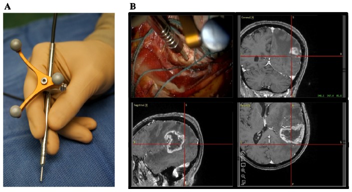
Raman spectroscopy system for intraoperative detection (A) Photograph of the hand-held contact probe, with the attached neuronavigation tracking unit. (B) Illustration of the probe being used intraoperatively, with the neuronavigation system showing the location of the tip of the probe (cross hairs) on the preoperative MR images.
The laser and the spectrometer are connected to a computer. A data acquisition and analysis LabView interface was developed for acquisition and real-time visualization of the Raman spectra and classification results. The acquired spectra are composed of wave-number shifts ranging from 381 cm−1 to 1653 cm−1, with a spectral resolution varying between 1.6 cm−1 and 2.1 cm−1 across the spectral domain. This area is consistent with the spectral shift region often referred to as the fingerprint region of biological samples [7]. The circular illumination spot size at the tip of the probe has a diameter of 0.5mm (area of 0.2mm2), determined using the optical and illumination design software Zemax (Zemax, LLC, WA, USA). The laser power used for in vivo measurements ranged from 37 to 64 mW measured using a power meter at the tip of the probe.
2.2 System calibration, instrument spectral response function and data pre-processing
Intensity calibration is necessary to ensure that the Raman spectra measured with different instruments are comparable. It corrects for the spectral response of the system, which depends on optics, the grating, filters and the detector. For example, the sensitivity of the CCD detector, as well as the transmission efficiency of the fiber optic cables in the probe, are dependent on the wavelength of the signal. Consequently, proper intensity calibration can ensure that the calibrated signal is minimally affected when a different probe system is used. A Deuterium Tungsten Halogen calibration standard (Ocean Optics, Dunedin, FL, USA) was used with a diffuse reflectance standard (Spectralon®), which has a spectrally flat reflectance over the visible and near-infrared range. The reflectance standard was illuminated by the white light lamp, and the measurement was taken with the probe pointing towards the Spectralon®. The instrument’s response R can be defined by
| (1) |
where Imeasured and Itrue are the measured and true spectra (company-provided) of the spectrally calibrated white lamp, respectively. In order to obtain a Raman spectrum corrected for the instrument’s spectral response, the measured spectrum is multiplied by the correction factor 1/R.
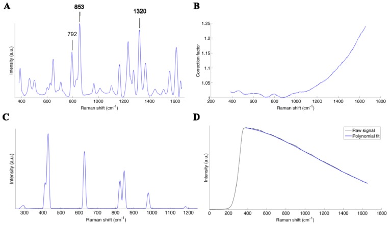
Light that is reemitted from the surface (following excitation at 785 nm) is transmitted to the spectrometer where it is spectrally separated using a diffraction grating: different spectral bands exit the grating with a different angle. Light is then detected using a rectangular CCD chip where the 7 detection fibers are projected on different lines (vertical direction on chip), and where the different wavelengths are associated with different sets of pixels along the horizontal direction on the chip. Since all detection fibers are imaging the same tissue area, a single spectrum is formed by summing the light intensity associated with the different lines of the CCD chips. Linearization is defined as the calibration of the wavenumber axis of the measurements. This calibration makes the correspondence between the pixel position (associated with the vertical line of the CCD chip) and the wavelength. A Mercury Argon (HgAr) spectral calibration lamp (Newport, Irvine, CA, USA) was used for this purpose, because it has emission peaks in the spectral range of the system. The lamp was used to illuminate the Spectralon®, and a measurement taken with the probe pointing towards the calibration standard. A correlation curve between the known peak wavelengths and the pixel positions was used to calibrate the wavenumber axis of the spectrometer. A correlation was also made with the Raman spectrum of the molecule acetaminophen (generic form Tylenol, McNeil Consumer Healthcare, Fort Washington, PA, USA) for verification purposes. The spectrum of acetaminophen, the correction factor and the spectrum of the HgAr lamp are shown in Fig. 10(A), 10(B) and 10(C) of the appendix, respectively.
In order to isolate the Raman signature of the interrogated tissue, a preprocessing procedure beyond the calibration steps outlined above must be applied to remove non-specific contributions. This includes a dark count subtraction to account for differences in ambient light conditions (see next section for an analysis of the different sources of ambient light), as well as background removal (e.g. intrinsic tissue fluorescence). The former is done by making a measurement with the laser turned off but with the same integration time as a tissue measurement. The latter is accomplished using an iterative polynomial fit method whereby the low frequency components of the signal are isolated and removed [14]. An example of a raw spectrum with the corresponding polynomial fit is provided in the appendix in Fig. 10(A) to 10(D). The resulting spectrum is then filtered with a Gaussian filter, and normalized by subtracting the mean and dividing by the variance of the spectrum.
2.3 Linearity of the signal with integration time and laser power
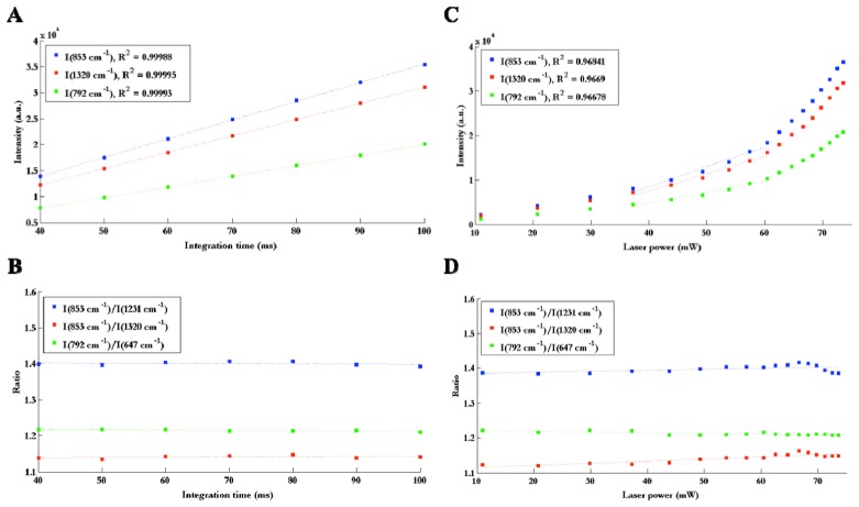
Linearity of the signal with output laser power and CCD exposure time (henceforth referred to as integration time) was verified by measuring the Raman spectrum of the molecule acetaminophen (generic form Tylenol, McNeil Consumer Healthcare, Fort Washington, PA, USA) while varying these two parameters. Three peaks were chosen (853, 792 and 1320 cm−1) for reference and the intensity of these peaks were measured as a function of laser power and integration time. Three ratios between peaks were also evaluated for each laser power and integration time, in order to determine quantitatively whether or not the shape of the spectra was stable.
Figure 2(A) reveals that the intensity of peaks is linear with integration time (R2 > 0.99). The ratios of peaks are also constant with integration time as demonstrated through a coefficient of variation of 0.77% (average variation over the three ratios considered here), which means that the shape of the spectrum is stable (Fig. 2(B)). Non-linearity occurs when varying laser power. As seen on Fig. 2(C), the curves (peak intensity vs. laser power) are approximately linear before 60 mW but do not follow the linear trend at high laser power. One possible explanation for this non-linearity is that the shape of the laser beam could change with power, which would lead to a reduced coupling efficiency between the probe and the laser, as well as between the probe and the spectrometer. It is also possible that there was an issue with the measurement of laser power at the tip of the probe. However, in the range of operation from 40 to 60 mW, the data shows linearity (R2 > 0.96) between peak intensity and laser power. Consequently, the observed non-linearity is not an issue for the use of the system in vivo as long as the system is operated within that range. It is also observed that the ratios of peaks are stable with laser power, with a coefficient of variation of 0.53% (average over the three ratios) between 40 and 60 mW, which means that the shape of the spectrum is also stable in that operating range (Fig. 2(D)).
Fig. 2.
(A) Intensity of 3 peaks on the Raman spectrum of Tylenol as a function of integration time, with linear fit and corresponding R2 value for each curve, (B) Ratios of Raman intensity peaks as a function of integration time. (C) Intensity of 3 peaks as a function of laser power, demonstrating linearity in the 40 to 60 mW range with corresponding R2 value associated with a linear fit performed in that range. (D) Ratios of Raman intensity peaks as a function of laser power.
2.4 Signal to noise ratio
Numerous studies have proven the potential of Raman spectroscopy for the analysis of biological samples, more specifically for cancer diagnosis [15–18]. However, the signal associated with inelastically scattered light is weak; it is several orders of magnitude smaller when compared to elastic scattering and other sources of background light such as intrinsic tissue fluorescence. Thus, one of the limiting factors for biological applications is stochastic noise, which can overwhelm the Raman signal that is tissue-specific [19–23]. Consequently, the inelastic scattering signal-to-noise ratio (SNR) is a very important concept in Raman spectroscopy, to determine the origin of the signal and evaluate the quality of the measurements. Characterization of the noise is particularly important for in vivo applications, where integration time must be limited for practical integration into clinical practice. Here we want to determine the SNR of the system for different integration times with the objective of finding the optimal optical data acquisition procedure for in vivo measurements. A possible method to evaluate the SNR of a spectrum is to take a large number of measurements of the same sample, and to analyze the variation of one or more known Raman peaks. The SNR for the peak intensity within a spectral band is defined as the average peak height of that band (), divided by the standard deviation of the peak height () [24]:
| (2) |
The peak height is defined as the difference between the peak intensity and the baseline intensity (example shown in Fig. 3). The baseline is chosen at a spectral shift where there is no peak in the spectrum, so only noise is present for the signal in that spectral band. In Fig. 3, SNR is calculated directly on the Raman signal, i.e., after background removal.
Fig. 3.
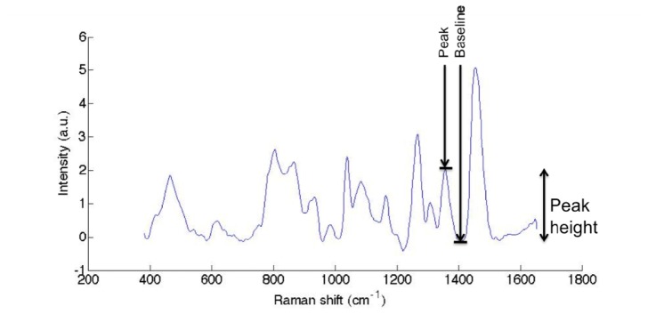
Raman spectrum of a solid phantom (polyurethane), illustrating the definition of peak height for the SNR evaluation.
An important noise source is shot noise, which comes from the discrete nature of the photons being measured by the CCD detector. Since the signal is a stream of discrete events, its standard deviation is proportional to the square root of the signal intensity (Poisson statistics) [25]. Therefore, if shot noise is dominant, SNR should depend on signal intensity as
| (3) |
Note that this is only valid for the raw signal, i.e., the number of photons actually measured on the detector prior to background subtraction. Other sources of noise can affect the signal such as thermal noise and dark current, which depend on the cooling temperature of the detector.
A Biomimic polyurethane-based phantom (INO, Quebec, CA) was used for the measurement of SNR for different integration times, and the peaks chosen for the calculation were based on their similar amplitude to the ones associated with in vivo Raman spectra measurements [8]. N = 50 spectra were measured for each acquisition time, ranging from 0.01s to 0.1s with increments of 0.01s. The signal to noise ratio was calculated for different integration times using Eq. (3) based on three peaks of the solid phantom’s spectra, namely wavenumber shifts 983cm−1, 1266cm−1 and 1358cm−1. Since the average peak height is proportional to the integration time, a square root function was fitted to the data (with laser power kept fixed) in order to evaluate the correspondence with Eq. (4) (Fig. 4(A)). The same peaks were used for the measurement of SNR on the Raman spectra, with the background not removed in order to verify whether or not the same trend applied. This was done to insure that Eq. (2) could be used to estimate SNR independent of whether the background was removed or not (Fig. 4(B)).
Fig. 4.
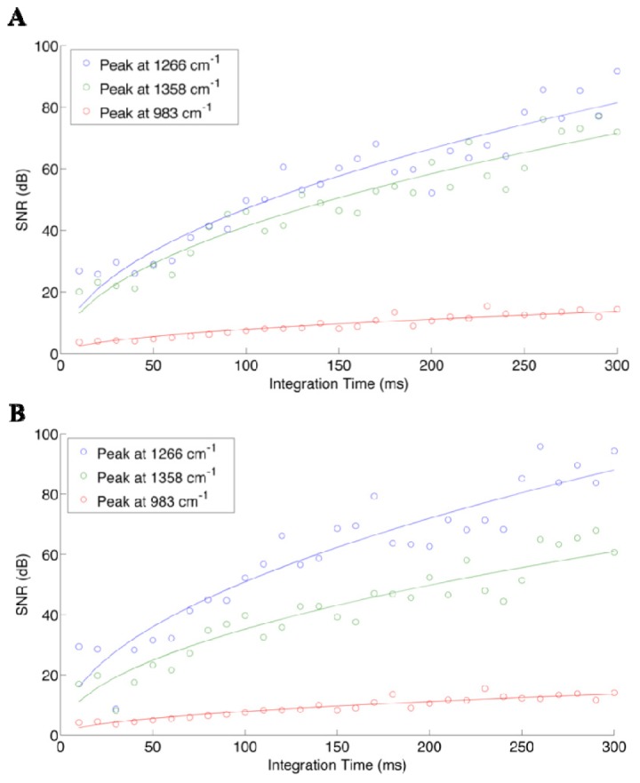
Signal to noise ratio of three different peaks on the spectra of the solid phantom, as a function of integration time (laser intensity kept fixed), calculated with Eq. (3) on (A) raw spectra and (B) Raman spectra, with the background subtracted using the fifth order polynomial fit.
An increase of the SNR with integration time is observed for the raw signal (no background subtraction), which is consistent with Poisson statistics. We observe the same increasing trend for the SNR of the Raman spectra, which reveals that the detectability of Raman peaks also depends highly on integration time. However, it is important to note that the intensity of the background can vary for different tissue types. For instance, if the measured spectrum has a high level of background, for equal integration times the SNR specific to the Raman signal will be smaller compared with a medium having a lower background. This is because the shot noise contribution is (in absolute terms) more important for the higher background medium, thus making it more difficult to isolate the tissue-specific Raman signature. As a result, despite the fact that peak selection for the analysis was made to represent peak heights observed in vivo, the actual intraoperative SNR values can be expected to be different due to background differences. It should also be noted that the SNR depends on the actual height of the particular peaks, which explains the inter-peaks SNR differences observed in Fig. 4. The relatively good fit of the data to the square root function tells us that shot noise is an important source of noise in our system, which depends on signal intensity.
Temperature-dependent noise was also assessed, by evaluating SNR for different cooling temperatures of the CCD in order to quantify the impact of thermal noise and dark current on the measured signals. The same solid phantom was used for this experiment, with 50 spectra measured for every camera temperature ranging from −20°C to −80°C with increments of 10°C.
Figure 5 demonstrates, as would be expected, that decreasing the temperature causes an increase in SNR for all peaks considered. Specifically, the SNR increases by ~15dB from 15dB for the 719cm−1 peak, by ~10dB from 10dB for the 900cm−1 peak, and by ~3dB from 2.5dB for the 1080cm−1 peak. These are substantial SNR increases, highlighting the advantage associated with minimizing thermal noise for intraoperative Raman spectroscopy measurements. In general, the the rate of increase (with decreasing temperature) is larger for those peaks having the largest SNR at the highest temperature. Decreasing camera temperature yields a multiplicative increase to SNR; this means that peaks with higher SNR will have larger slopes in Fig. 5.
Fig. 5.
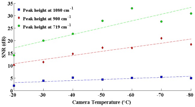
Signal to noise ratio of three different peaks on the spectra of the solid phantom, as a function of the camera temperature.
2.5 Sources of spectral artifacts: ambient lights
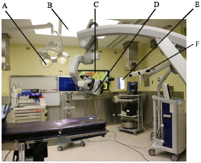
The use of Raman spectroscopy in the operating room (OR) is challenging because there are typically several sources of electromagnetic radiation overlapping with the detection range of the hand-held system. These sources are represented in the photograph in Fig. 8, which is showing a typical OR. Common sources include: (A) surgical lights (Dr Mach, model 380, Germany) that provide lighting in and around the operative field, (B) conventional fluorescent light sources used to light-up the room, (C) liquid-crystal display (LCD) monitors used, e.g., to provide live images of the field of view of the microscope, (D) white-light source from the OPMI Pentero surgical microscope system directly illuminating the surgical cavity (Zeiss, Oberkochen, Germany), (E) windows with a view to the exterior of the OR, and (F) neuronavigation system (Medtronic) infrared sources (Fig. 6).
Fig. 6.
Sources of ambient light in the operating room: (A) surgical lights (Dr Mach, model 380, Germany) (B) fluorescent light sources (C) liquid-crystal display (LCD) monitors (D) white-light source from the OPMI Pentero surgical microscope (Zeiss, Oberkochen, Germany) (E) windows with a view to the exterior of the OR (F) neuronavigation system (Medtronic) infrared sources.
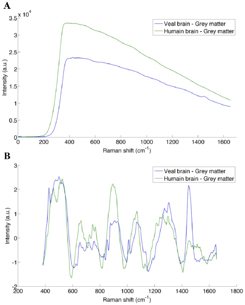
Here we present a detailed quantitative assessment of the impact of these light sources on our ability to detect the inelastic scattering signature of tissue with the Raman spectroscopy instrument. Veal brain was used for this experiment, since it has been determined to have a Raman signature (and background) consistent with that of human brain tissue (see Fig. 11(A) in appendix comparing typical spectra for human and veal brain). The veal brain was placed on the operating table in the OR, and the probe was placed in a fixed position in contact with the surface of the brain (on gray matter). A spectrum was measured with the probe under every ambient light source separately, varying the intensity of the sources whenever possible. The intensity of the surgical lights (C) can be varied from 1/7 to 7/7 intensity, and a high intensity (7/7) was used as well as a low intensity (3/7) for the measurements. The surgical lights can also be moved, so that sources point toward the sample (direct) or away from the sample (indirect). Therefore, four illumination states of the surgical light were used in this experiment, including: high direct (HD), low direct (LD), high indirect (HI) and low indirect (LI). The light source of the microscope is a white xenon source, and a blue low pass filter can be used for fluorescence-guided surgery. The intensity of the light can be adjusted from 0 to 100%: intensities of 30%, 60% and 100% were used for the analysis. In order to evaluate the change of the spectrum in the course of the experiment, a control measurement was acquired between every measurement. The control measurements consists of spectra acquired on veal brain with no light sources turned on; this included black covers blocking light passage through the windows insuring acquisition under pitch dark conditions.
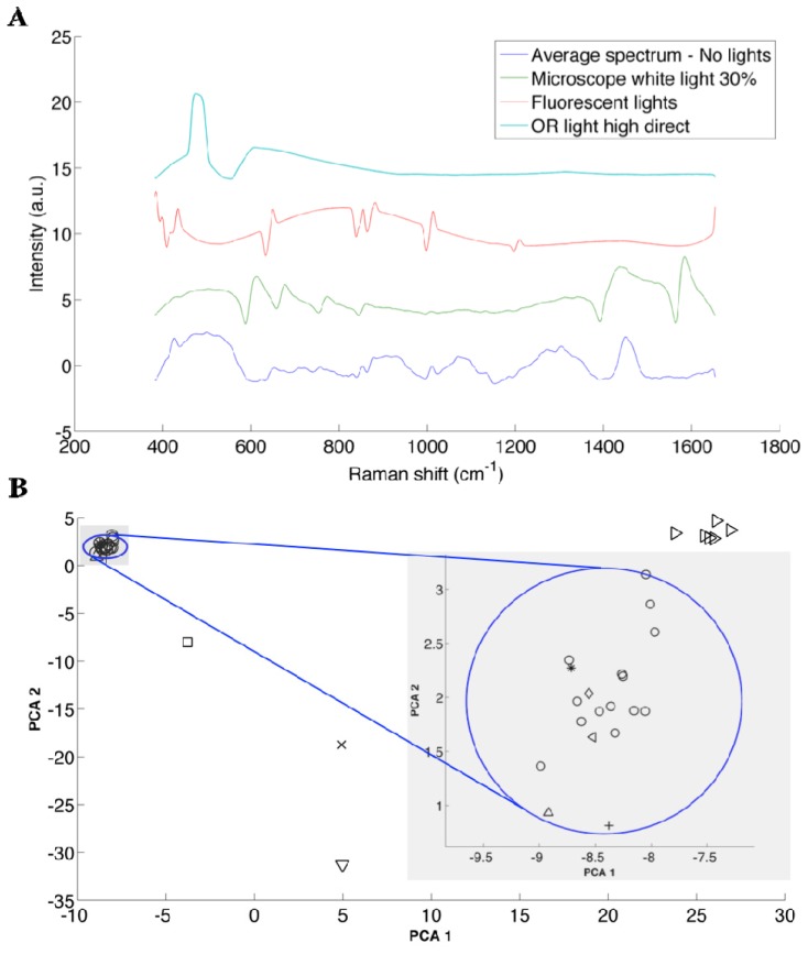
Qualitative visual inspection of the spectra (Fig. 7(A)) can reveal the impact on Raman spectra associated with different ambient light conditions. For example, undesirable spectral artifacts are observed on the Raman spectra (after background removal) due to intense peaks in the spectra from the light sources. However, in order to quantitatively assess the impact of the light sources, a principal component analysis (PCA) technique was used. The technique determines the level with which different sources could affect and compromise the detection of the inelastic scattering signal. Briefly, PCA is a statistical method that uses an orthogonal transformation to convert a set of variables (here, wave numbers) into principal components. The principal components are a set of values of linearly uncorrelated variables, from which we can obtain the measured spectra by a weighted linear combination. The transformation is such that the first principal components account for the most variability in the data, and each following component has the highest variance possible with the condition that it is orthogonal to the preceding component [26]. In our case, the scores of principal components 1 and 2 captured 65% and 18% of the spectral variance in the measurements, respectively. Since these components altogether capture more than 80% of the information contained in the spectra, for simplicity here we are only considering the first 2 components.
Fig. 7.
(A) Representative spectra acquired on veal brain under the ambient light conditions that caused the largest spectral artifacts not specific to inelastic scattering. An offset has been added along the intensity axis to clearly separate all spectra. (B) PCA scatter plot of score 1 versus score 2 of Raman spectra of veal brain for every ambient light conditions considered: no lights (o), LCD monitor ( + ), IR source of the neuronavigation system ON (*), Microscope blue and white light with different intensities (>), surgical lights HD (x), surgical lights LD (square), surgical lights LI (diamond), surgical lights HI (^), fluorescent lights (v), external lights (<). K-means cluster analysis was used to group observations into 5 clusters, and the one including all the measurements with the condition “no lights” is represented by the circle. The radius of that circle is the largest distance between a point in the cluster and the centroïd of that cluster. This is shown more clearly in the zoom of this section of the plot.
The PCA plot of these 2 scores (associated with the first 2 principal components) shows that all the spectra that were acquired with the condition no lights are grouped within the cluster that is circumscribed by the circle in Fig. 7 (see legend in Table 1). Inspection of the figure shows that the spectra acquired with the following light sources turned on are also contained within the circle: Medtronic system, LCD monitor and OR light when pointed away from the sample. Further, a K-means clustering technique was used to group the observations (spectra) into different clusters based on Euclidian distance in such a way that objects in the same cluster are very similar and objects in different clusters are very distinct. The algorithm was used to determine the position of the centroid of the clusters, and the circle in Fig. 7(B) has its origin on the centroid of that cluster, and its radius is the largest distance between a point in the cluster and the centroid of that particular cluster. The plot also shows that the spectra acquired with the other sources (microscope, fluorescent lights, OR lights pointed directly at the sample) are significantly different. The spectra of veal brain altered by these most significant light sources, as well as the control (no light sources) are shown in Fig. 7(A). An artificial shift in the intensity (y-axis) was added to each spectrum in order for them to be separated, for clarity. The sources that are inside the circle have an insignificant impact on the measurements, since they don’t produce larger differences than those observed between measurements under the same condition (no light). Therefore, OR lights pointed indirectly, LCD screens, and exterior lights coming through the windows can be used during Raman spectroscopic measurements in the operating room. However, the ones that are outside the blue circle should not be used during Raman spectrum measurements (microscope light, fluorescent lights and OR light point directly at the sample), since they affect the signal significantly. Despite the fact that the neuronavigation IR source is inside the circle, it can cause saturation of the signal, which we have observed previously during intraoperative measurements. Consequently, these sources must be pointed away during the measurements.
Table 1. Ambient light sources and corresponding symbols, used in Fig. 7.
| ○ | No lights | ⬜ | Surgical light low direct |
| + | LCD monitors | ◇ | Surgical light low indirect |
| IR source - Neuronavigation | △ | Surgical light high indirect | |
| ▷ | Microscope light | ▽ | Fluorescent lights |
| x | Surgical light high direct | ◁ | External light |
3. Clinical application: classification of necrotic tissue, cancer and normal brain
Here we are presenting the results of a clinical study involving 10 glioma patients testing the hypothesis that necrotic tissue can be differentiated from vital tissue (normal brain or cancer tissue) using Raman spectroscopy. In the previous sections we have determined that the laser must be operated at powers between 40 to 60 mW in order to be in the linear range, and that the system can provide appreciable SNR levels even when operated at integration times consistent with real-time detection: here an integration time of 0.05s will be used for clinical practicality. The temperature of the camera was set to −40°C. All the light sources mentioned in the previous section were turned off while the measurements were taken, except the ones that were showed not to have a significant impact on the measurement, namely: exterior lights, surgical light at low intensity and pointed away from the measurement location, and LCD monitors.
The intraoperative data acquisition procedure is described previously [8]. Briefly, before each surgical procedure, the probe is sterilized using the STERRAD system, which is used for standard low-temperature sterilization procedure, using proprietary gas plasma technology to efficiently eliminate toxic residue from medical devices. The navigation attachment on the probe (Medtronic SureTrak) allows the surgeon to use the neuronavigation system (Medtronic, MN, USA) with pre-operative MR-images to target measurement locations of normal brain, cancer and necrotic tissue. Even though state-of-art neuronavigation techniques are used in this study, MRI information is used only qualitatively for visualization and estimation of the location of each Raman measurement on the pre-operative images. A “dark count” spectrum with an integration time of 0.05s was first taken with the probe in direct contact with the tissue, but with the laser off. Then, 3 spectra were taken each with 0.05s integration time. The surgeon collected a tissue sample (average size of ~0.5mm x ~0.5 mm and depth of ~3 mm) immediately following the measurement at the same location, used for reference diagnosis. A figure showing the surgeon handling the probe is shown in Fig. 8 with the corresponding video presented as supplemental material.
Fig. 8.
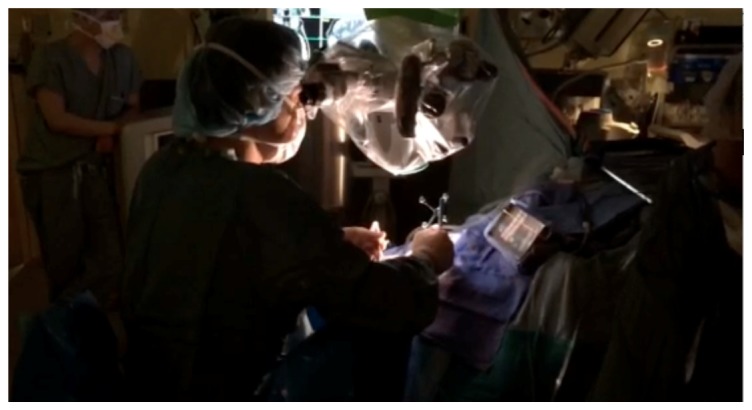
Image grabbed from the video (see Media 1 (3MB, MOV) ) showing the surgeon handling the probe.
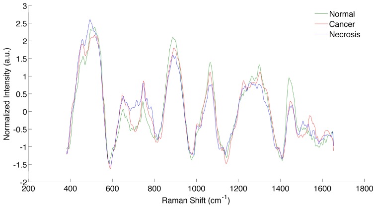
Each sample was fixed in 10% buffered formalin, processed and 4 microns sections are cut and stained with H&E (hematoxylin & eosin). A neuropathologist categorized each sample, based on WHO pathological criteria, which was used as a reference for this study [27]. This grading criteria for diffuse glioma grade II to III and IV (Glioblastoma) is based on cellularity, nuclear atypia, mitoses, endothelial proliferation and necrosis. The presences of endothelial proliferation and/or necrosis are the hallmarks of glioblastoma. The histology is assessed based on the morphology of the cells and the criteria see above to determine the type and the grade of the glioma. The spectroscopic data was pre-processed (dark count subtraction, background removal using an iterative polynomial method, filtering and normalization) and analyzed with the Boosted trees classification algorithm [8]. Boosted Trees operates by constructing an ensemble of decision trees based on the training data with known classes. The classification can then be given test data (spectra), where the classes are unknown, and will predict the classes of the test data. The implementation used ensures that measurements with large negative margins are given less weight than other measurements [28]. This minimizes the negative effect that mislabeled training data may have on classification accuracy. Samples were excluded from analysis if the spectra were saturated. A total number of 70 spectra were measured in 10 patients (12 normal brain, 28 cancer and 30 necrotic samples). The spectra of normal brain, cancer and necrosis, averaged over all measurements, are shown in Fig. 9.
Fig. 9.
Spectra of normal brain, cancer and necrotic tissue, averaged over all measurements.
The tissue types were divided into two categories in order to evaluate the performance of the algorithm: necrosis and vital tissue (including cancer and normal tissue). Using a leave-one-out cross-validation approach with the Boosted trees algorithm, we achieved a classification accuracy of 87%, sensitivity of 84% and specificity of 89%.
4. Discussion
A probe system and data analysis methods for Raman spectroscopic measurements have been previously tested in 17 glioma patients [8]. The system has already been demonstrated to be well-suited for intraoperative decision making during brain cancer surgery. Here we have presented specific details pertaining to the calibration and required data pre-processing steps as well as an analysis of factors leading to optimal data acquisition parameters in preparation for a larger scale clinical study. The system was first calibrated and its spectral response precisely measured. The data pre-processing steps used with the system are: dark count subtraction, background removal using an iterative polynomial method, filtering and normalization. The measured Raman signal shows linearity with integration time, and spectral shape remains unchanged when varying integration time. A linear relationship was shown between Raman-specific signal (after data pre-processing steps were applied) and laser power in the range operation, from 40 mW to 60 mW. The observed non-linearity at higher laser power could be explained by the change in shape of the laser at high powers, or by the measurement of the power at the output of the probe.
The SNR of the system was measured with different samples, by taking multiple measurements and evaluating the mean and standard deviation of the peak height (Eq. (2).1). A typical square root relationship between integration time and SNR was observed (before and after data pre-processing steps were applied), revealing stochastic photonic noise as a dominant source of noise in the signal. From previous work, an integration time of 0.05s is sufficient to discriminate between tissue containing cancer cells and normal brain with an accuracy of 92%, a sensitivity of 93% and a specificity of 91% [8]. Here it has been demonstrated that modest increases in integration time can improve SNR and thus potentially further improve diagnostic accuracy. In fact, as shown in Fig. 4, increasing the integration time from 0.05s to 0.1s or 0.2s would increase the SNR by 41% or 73%, respectively. However longer integration times can limit the clinical practicality of the technique, which needs to be real-time in order to minimize disruption to the neurosurgical workflow. Thus a trade-off must be made between integration time and SNR, encouraging efforts made on other fronts to fully exploit the diagnostic potential of the Raman effect. A higher SNR would be helpful, for example, if a chemometrics analysis was performed with in vivo Raman spectrum. In fact, projection of spectra from molecular species on a tissue spectrum is very sensitive to noise in the data. Typically, molecular characterization and quantification is performed with spectra acquired with integration times of ~1 to 10 seconds, which can be challenging for clinical implementation [29–31]. Also, distinguishing between different tumor grades, which potentially relies on subtle spectral differences, might be achievable with higher SNR levels. The relationship between noise and camera temperature was also assessed, by measuring multiple measurements on a phantom, at different cooling temperatures. It was revealed that there is a linear relationship between SNR and temperature, and that the SNR could be increased by up to 35% (in dB) by simply decreasing the detector’s temperature from −40°C to −80°C. Therefore, the camera must be cooled to the minimum temperature in order to minimize thermal noise, hence increasing the quality (SNR) of the measured data.
The influence of potential sources of ambient light in operating rooms was evaluated in order to find the optimal conditions for the measurement of Raman spectra in vivo. The sources that have the most influence on the measurements were determined to be the surgical microscope light sources (white or blue), ambient fluorescent lights and standard operating room (OR) lights when they are pointed directly at the measured sample. As a result: (i) the microscope light source and the fluorescent lights must always be turned off while the spectroscopic measurements are taken, (ii) standard OR lights can be left turned on as long as they are pointed away from the sample. Moreover, the IR source of the neuronavigation system has been shown to have little impact on the measured spectra. This is due to the fact that the IR source’s spectrum has no distinguishable peaks (i.e., the spectrum is smooth and monotonically increasing as a function of frequency), and despite it contributing to the raw spectra, removal is achieved, as with the background, using the polynomial fitting technique (see section 2.2). However, in some instances it was observed that this source of ambient light caused detector saturation when the IR source was pointed directly at the measurement location. For this reason, the IR source should preferably be pointed away (or momentarily deactivated) while the measurement is taken. The exterior lights (light passing through the windows) showed little impact on the Raman spectra, so there is in most cases no need for window covers. However, the levels of exterior light can vary between different ORs and thus it is recommended that OR-specific tests be made evaluate their impact. The LCD monitors did not appear to have a significant influence on the measured spectra, but care must be taken to insure that the screens are not too close to where measurements are made.
In conclusion, a small in-human clinical study was performed where in vivo spectroscopic data acquisition was achieved under the experimental conditions determined to be optimal for the probe system operation and acceptable ambient light conditions. The results of this study provide evidence that necrotic tissue can be detected using inelastic scattering. This is an important result for the on-going development [13] of optical biopsy techniques where the detection of necrosis is crucial to insure biopsy samples are collected in tumor areas, thus improving the diagnostic yield of the procedure.
APPENDIX
Fig. 10.
Spectra illustrating the different steps associated with the data preprocessing procedure: (A) Raman spectrum of Acteminophen acquired with the probe and used as a reference for calibration of the wave number axis (x-axis), (B) Correction factor to account for the system response, obtained from the calibrated white light lamp and a reflectance standard, (C) Spectrum of the lamp used as a reference for calibration of the x-axis, (D) Raw Raman spectrum from human grey matter (black line) with the corresponding polynomial fit used to remove the background.
Fig. 11.
Comparison of the Raman spectra of veal brain (blue) and human brain (green) for (A) raw spectra and (B) spectra with the background removed.
References and links
- 1.Henriksson R., Asklund T., Poulsen H. S., “Impact of therapy on quality of life, neurocognitive function and their correlates in glioblastoma multiforme: a review,” J. Neurooncol. 104(3), 639–646 (2011). 10.1007/s11060-011-0565-x [DOI] [PMC free article] [PubMed] [Google Scholar]
- 2.Stummer W., Meinel T., Ewelt C., Martus P., Jakobs O., Felsberg J., Reifenberger G., “Prospective cohort study of radiotherapy with concomitant and adjuvant temozolomide chemotherapy for glioblastoma patients with no or minimal residual enhancing tumor load after surgery,” J. Neurooncol. 108(1), 89–97 (2012). 10.1007/s11060-012-0798-3 [DOI] [PMC free article] [PubMed] [Google Scholar]
- 3.Smith J. S., Chang E. F., Lamborn K. R., Chang S. M., Prados M. D., Cha S., Tihan T., Vandenberg S., McDermott M. W., Berger M. S., “Role of Extent of Resection in the Long-Term Outcome of Low-Grade Hemispheric Gliomas,” J. Clin. Oncol. 26(8), 1338–1345 (2008). 10.1200/JCO.2007.13.9337 [DOI] [PubMed] [Google Scholar]
- 4.Capelle L., Fontaine D., Mandonnet E., Taillandier L., Golmard J. L., Bauchet L., Pallud J., Peruzzi P., Baron M. H., Kujas M., Guyotat J., Guillevin R., Frenay M., Taillibert S., Colin P., Rigau V., Vandenbos F., Pinelli C., Duffau H., “Spontaneous and therapeutic prognostic factors in adult hemispheric World Health Organization Grade II gliomas: a series of 1097 cases: clinical article,” J. Neurosurg. 118(6), 1157–1168 (2013). 10.3171/2013.1.JNS121 [DOI] [PubMed] [Google Scholar]
- 5.Stummer W., Tonn J.-C., Mehdorn H. M., Nestler U., Franz K., Goetz C., Bink A., Pichlmeier U., ALA-Glioma Study Group , “Counterbalancing risks and gains from extended resections in malignant glioma surgery: a supplemental analysis from the randomized 5-aminolevulinic acid glioma resection study. Clinical article,” J. Neurosurg. 114(3), 613–623 (2011). 10.3171/2010.3.JNS097 [DOI] [PubMed] [Google Scholar]
- 6.Talos I.-F., Zou K. H., Ohno-Machado L., Bhagwat J. G., Kikinis R., Black P. M., Jolesz F. A., “Supratentorial low-grade glioma resectability: statistical predictive analysis based on anatomic MR features and tumor characteristics,” Radiology 239(2), 506–513 (2006). 10.1148/radiol.2392050661 [DOI] [PMC free article] [PubMed] [Google Scholar]
- 7.Movasaghi Z., Rehman S., Rehman I. U., “Raman Spectroscopy of Biological Tissues,” Appl. Spectrosc. Rev. 42(5), 493–541 (2007). 10.1080/05704920701551530 [DOI] [Google Scholar]
- 8.Jermyn Michael, Mok Kelvin, Mercier Jeanne, Desroches Joannie, Pichette Julien, Saint-Arnaud Karl, Bernstein Liane, Guiot Marie-Christine, Petrecca Kevin, Leblond Frederic, “Intraoperative brain cancer detection with Raman spectroscopy in humans,” Sci. Transl. Med. 7, 274ra19 (2015). [DOI] [PubMed] [Google Scholar]
- 9.Kongkham P. N., Knifed E., Tamber M. S., Bernstein M., “Complications in 622 Cases of Frame-Based Stereotactic Biopsy, a Decreasing Procedure,” Can. J. Neurol. Sci. 35(1), 79–84 (2008). 10.1017/S0317167100007605 [DOI] [PubMed] [Google Scholar]
- 10.Muragaki Y., Chernov M., Maruyama T., Ochiai T., Taira T., Kubo O., Nakamura R., Iseki H., Hori T., Takakura K., “Low-grade glioma on stereotactic biopsy: how often is the diagnosis accurate?” Minim. Invasive Neurosurg. 51(5), 275–279 (2008). 10.1055/s-0028-1082322 [DOI] [PubMed] [Google Scholar]
- 11.Sawin P. D., Hitchon P. W., Follett K. A., Torner J. C., “Computed Imaging-Assisted Stereotactic Brain Biopsy: A Risk Analysis of 225 Consecutive Cases,” Surg. Neurol. 49(6), 640–649 (1998). 10.1016/S0090-3019(97)00435-7 [DOI] [PubMed] [Google Scholar]
- 12.Glantz M. J., Burger P. C., Herndon J. E., 2nd, Friedman A. H., Cairncross J. G., Vick N. A., Schold S. C., Jr., “Influence of the type of surgery on the histologic diagnosis in patients with anaplastic gliomas,” Neurology 41(11), 1741–1744 (1991). 10.1212/WNL.41.11.1741 [DOI] [PubMed] [Google Scholar]
- 13.Goyette A., Pichette J., Tremblay M.-A., Laurence A., Jermyn M., Mok K., Paulsen K. D., Roberts D. W., Petrecca K., Wilson B. C., Leblond F., “Sub-diffuse interstitial optical tomography to improve the safety of brain needle biopsies: a proof-of-concept study,” Opt. Lett. 40(2), 170–173 (2015). 10.1364/OL.40.000170 [DOI] [PubMed] [Google Scholar]
- 14.Zhao J., Lui H., McLean D. I., Zeng H., “Automated Autofluorescence Background Subtraction Algorithm for Biomedical Raman Spectroscopy,” Appl. Spectrosc. 61(11), 1225–1232 (2007). 10.1366/000370207782597003 [DOI] [PubMed] [Google Scholar]
- 15.Crow P., Stone N., Kendall C. A., Uff J. S., Farmer J. A., Barr H., Wright M. P. J., “The use of Raman spectroscopy to identify and grade prostatic adenocarcinoma in vitro,” Br. J. Cancer 89(1), 106–108 (2003). 10.1038/sj.bjc.6601059 [DOI] [PMC free article] [PubMed] [Google Scholar]
- 16.Stone N., Kendall C., Smith J., Crow P., Barr H., “Raman spectroscopy for identification of epithelial cancers,” Faraday Discuss. 126, 141–157 (2004). 10.1039/b304992b [DOI] [PubMed] [Google Scholar]
- 17.Draga R. O. P., Grimbergen M. C. M., Vijverberg P. L. M., van Swol C. F. P., Jonges T. G. N., Kummer J. A., Ruud Bosch J. L. H., “In Vivo Bladder Cancer Diagnosis by High-Volume Raman Spectroscopy,” Anal. Chem. 82(14), 5993–5999 (2010). 10.1021/ac100448p [DOI] [PubMed] [Google Scholar]
- 18.Mahadevan-Jansen A., Richards-Kortum R. R., “Raman spectroscopy for the detection of cancers and precancers,” J. Biomed. Opt. 1(1), 31–70 (1996). 10.1117/12.227815 [DOI] [PubMed] [Google Scholar]
- 19.Ramírez-Elías M. G., Alda J., González F. J., “Noise and artifact characterization of in vivo Raman spectroscopy skin measurements,” Appl. Spectrosc. 66(6), 650–655 (2012). 10.1366/11-06495 [DOI] [PubMed] [Google Scholar]
- 20.D. Van de Sompel, E. Garai, C. Zavaleta, and S. S. Gambhir, “Comparison of Gaussian and poisson noise models in a hybrid reference spectrum and principal component analysis algorithm for Raman spectroscopy,” in SPIE BiOS International Society for Optics and Photonics 8590, 85900I (2013). [Google Scholar]
- 21.Barman I., Kong C.-R., Singh G. P., Dasari R. R., “Effect of photobleaching on calibration model development in biological Raman spectroscopy,” J. Biomed. Opt. 16(1), 011004 (2011). 10.1117/1.3520131 [DOI] [PMC free article] [PubMed] [Google Scholar]
- 22.Quintero L., Matthäus C., Hunt S., Diem M., “Denoising of single scan Raman spectroscopy signals,” in SPIE BiOS International Society for Optics and Photonics 7568, 7568171 (2010). [Google Scholar]
- 23.Barman I., Dingari N. C., Singh G. P., Soares J. S., Dasari R. R., Smulko J. M., “Investigation of noise-induced instabilities in quantitative biological spectroscopy and its implications for noninvasive glucose monitoring,” Anal. Chem. 84(19), 8149–8156 (2012). 10.1021/ac301200n [DOI] [PMC free article] [PubMed] [Google Scholar]
- 24.McCreery R. L., Raman Spectroscopy for Chemical Analysis (John Wiley & Sons, 2005). [Google Scholar]
- 25.Smulko J. M., Dingari N. C., Soares J. S., Barman I., “Anatomy of noise in quantitative biological Raman spectroscopy,” Bioanalysis 6(3), 411–421 (2014). 10.4155/bio.13.337 [DOI] [PubMed] [Google Scholar]
- 26.Abdi H., Williams L. J., “Principal component analysis,” Wiley Interdiscip. Rev. Comput. Stat. 2(4), 433–459 (2010). 10.1002/wics.101 [DOI] [Google Scholar]
- 27.Louis D. N., Ohgaki H., Wiestler O. D., Cavenee W. K., Burger P. C., Jouvet A., Scheithauer B. W., Kleihues P., “The 2007 WHO Classification of Tumours of the Central Nervous System,” Acta Neuropathol. 114(2), 97–109 (2007). 10.1007/s00401-007-0243-4 [DOI] [PMC free article] [PubMed] [Google Scholar]
- 28.Y. Freund, A more robust boosting algorithm, ArXiv09052138 Stat (2009) (available at http://arxiv.org/abs/0905.2138).
- 29.Beljebbar A., Dukic S., Amharref N., Manfait M., “Ex vivo and in vivo diagnosis of C6 glioblastoma development by Raman spectroscopy coupled to a microprobe,” Anal. Bioanal. Chem. 398(1), 477–487 (2010). 10.1007/s00216-010-3910-6 [DOI] [PubMed] [Google Scholar]
- 30.Bergner N., Krafft C., Geiger K. D., Kirsch M., Schackert G., Popp J., “Unsupervised unmixing of Raman microspectroscopic images for morphochemical analysis of non-dried brain tumor specimens,” Anal. Bioanal. Chem. 403(3), 719–725 (2012). 10.1007/s00216-012-5858-1 [DOI] [PubMed] [Google Scholar]
- 31.Kalkanis S. N., Kast R. E., Rosenblum M. L., Mikkelsen T., Yurgelevic S. M., Nelson K. M., Raghunathan A., Poisson L. M., Auner G. W., “Raman spectroscopy to distinguish grey matter, necrosis, and glioblastoma multiforme in frozen tissue sections,” J. Neurooncol. 116(3), 477–485 (2014). 10.1007/s11060-013-1326-9 [DOI] [PubMed] [Google Scholar]


