Abstract
A low-cost, high performance RF coil-pair for MR imaging of mouse brain is described. A surface receiving coil is used for high spin-sensitivity, while a larger transmit coil, located outside the mouse holder, delivers good B1 uniformity across the brain with reasonable efficiency. The volume coil is constructed with an open architecture, making experimental setup easy and providing clear access to the head of the mouse. Each coil is switched between active and inactive modes using PIN diodes driven by a small amplifier external to the spectrometer. Because of this active decoupling, there is no requirement for orthogonal orientation of the coils. The coil pair is platform independent, requiring only a transmit/receive (T/R) signal to switch the amplifier that drives the PIN diodes, and can therefore be used with virtually any commercial or home-built MR scanner.
Introduction
Animal models are used extensively in MRI, both in the development of new imaging methodology and as platforms for the study of disease progression and therapeutic response. The majority of these animal studies employ mice and the mouse brain has become a particularly important target for the study of a wide variety of diseases, including various white-matter diseases such as Alzheimer’s disease (1-3), multiple sclerosis (4-6), and cancer (e.g., high- and low-grade brain tumors) (7-9). These studies require MR images that provide both high sensitivity (signal-to-noise) and high spatial resolution. There are several different approaches to the design of RF coil(s) for these studies.
A single transmit-receive coil is a particularly simple solution. To maximize receiving sensitivity and allow MR images of brain to be collected with small voxel sizes, this single coil should be small; from this perspective, a small surface coil would be an excellent choice. However, small coils (and especially small surface coils) have poor B1 uniformity, so that the nutation angle will vary across the imaged region, unless this is confined to a quasi-planar geometry. This is a particular problem for echo and multiple echo sequences, including diffusion-weighted imaging, which is a mainstay of our laboratory (4,6,10,11). Adiabatic pulses (12-14)can be used to circumvent the inhomogeneous B1, but such pulses are longer in duration and result in a distribution of echo times, TE. In our case, we would like the ability to use adiabatic pulses without requiring their use.
A second approach is to use separate transmit and receive coils, with each optimized for its task. Thus, a high sensitivity small surface receive coil is combined with a larger uniform-excitation transmit coil. We (and others) have used this approach with success (15-20). However, the high Q-factors of the individual transmit and receive coils require that these coils be very accurately oriented orthogonal to each other, to avoid coupling (and, hence, frequency-splitting) of the LC resonances. The process of geometrically isolating the two coils is time-consuming and increases the experimental setup time. In addition, we are seldom able to orient the coils exactly orthogonal to one another; the residual coupling between the coils can lead to degradation in image quality.
The approach we present here is an actively decoupled coil-pair, with a volume- coil transmitter and a surface-coil receiver. Each coil is disabled by PIN diode circuitry when the other coil is active, completely eliminating coupling effects. While others have used such schemes (15-18,20), the present design offers excellent RF performance, is particularly low cost, is platform independent so that it can be used on any commercial or home-built MR scanner, and uses an open-architecture volume coil that affords ready access to the mouse during set-up.
Design
The overall two-coil arrangement is shown in Figure 1. Separate coaxial cables, T and R, carry the RF of the transmit and receive coils to and from the spectrometer; for our Varian INOVA (Varian NMR Instruments, Palo Alto, CA) spectrometer, these connections are at the probe interface console (PIC) unit. The DC bias voltages required to switch the coils’ PIN diodes are carried on the same coaxial cables. These bias voltages are +5 volts in transmit (current limited to 25 mA) to turn on each PIN diode and −18 volts in receive to bias the PINs off. Small bias-tees serve to combine the RF and dc voltages; having only one cable connected to each coil simplifies the design and decreases the likelihood of user errors during setup.
Figure 1.
Overall connection diagram for the actively decoupled transmit (volume) and receive (surface) coils. The bias-Tees add the PIN diode DC bias to the RF lines (T, R) that run from the scanner to the transmit and receive coils.
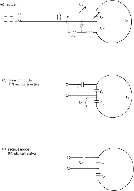
Figure 2 shows a schematic drawing of the receiving surface coil, which is tuned to 200 MHz, the resonance frequency for hydrogen MR in our 4.7 T magnets. The RF choke (RFC) brings the DC bias voltage to the PIN diode, switching it on (conducting mode) during transmit and off during receive. The equivalent circuits (RF only) in each mode are also presented in Figure 2. In transmit, the coil L2 and capacitor C2 form a high-impedance parallel resonance, blocking current along the NMR surface coil L1. The coil L2 is kept small, with short leads, and is wound with equal numbers of clockwise and counterclockwise turns, so that little or no voltage is induced in L2 by the transmit B1 field. We note that good blocking of currents in the surface coil is a requirement because such currents would distort the B1 field in the nearby imaged region.
Figure 2.
Receive coil. Actual circuit (a) and RF-only equivalent circuits ((b) transmit mode; (c) receive mode) for the receive surface coil. The L2C2 combination is a parallel trap to block current on the surface coil L1 during transmit.
In receive mode, the coil L2 is removed completely from the circuit (except for the small off-state capacitance of the PIN diode, which causes a small tuning shift). Overall, the capacitors C1 and C2 serve as a ‘center-tap,’ placing the coax ground at the approximate electrical center of the coil (electrostatic balancing). Tuning of the surface coil is simplified by making sure that the adjustable capacitor is only a small fraction of the total C1.
We construct our receive coil as a 1.6 cm diameter, single-turn surface coil from 1-mm diameter tinned copper wire. All components are soldered to copper adhesive tape on perforated circuit board. The PIN diode is a non-magnetic unit (MA4P7464F-1072) from M/A-COM (Lowell, MA). The coil L2 is approximately 0.8 cm long and 2 mm diameter, with a total of 4 turns. Coil L2 is tuned together with C2 by shorting the PIN diode and adjusting the resonant frequency to 200 MHz (determined using an inductively coupled ‘sniffer loop’ and reflection bridge) with the rest of the circuit board disconnected. The RFC is constructed using 25 turns of 30 AWG enameled copper wound as a single-layer on an Ohmite 0.5 watt, high-value (180 KΩ) carbon-composition resistor that serves as a coil form. The fixed capacitors are small ceramic disks; C2 is 22 pf and C1 is 18 pf in parallel with a small (1-5 pf) Johanson 9300 series ceramic trimmer (Boonton, NJ). The RG-58/U coax cable has two traps to eliminate the effects of RF current flowing on the outside of the shield. The coax cable is coiled (3 turns, 4 cm in diameter) and taped to maintain the coiled shape; this coil and its stray capacitance were chosen (in separate bench measurements of coax traps) to resonate near 200 MHz. The first trap is 14 cm from the receiver coil circuit board and the second trap is 30 cm further from the board (neither is critical). The traps make the tuning immune to the effects of touching the coax jacket, either beyond the second trap or even between the two traps.
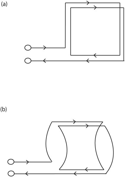
A schematic drawing of the geometry of the transmitter coil is shown in Figure 3. Starting with the two-turn coil of Figure 3a, the coil produces a B1 field normal to the page (and perpendicular to B0). To allow ready access to the mouse and mouse-holding fixture, the vertical legs in 3a are curved in and out of the page, more or less conforming to the cylindrical shape of the mouse holder, as in Figure 3b. This geometry is essentially that of Alderman and Grant (21), except that the two loops here are in series. The B1 field may be regarded as coming primarily from the horizontal legs, the legs directly above and below the mouse, in Figures 3a and 3b. In our case, the coil diameter is about 5 cm, slightly larger than the mouse holder, with an axial length of 4 cm. The mouse brain is approximately in the center of this coil.
Figure 3.
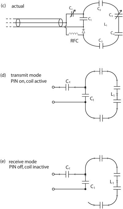
Transmit coil. The starting two-turn geometry in (a) is modified in (b) to the actual coil shape by curving the vertical legs to provide unobstructed access for the mouse and the mouse holder. The full circuit in (c) shows the multiple stations of tuning capacitors C1-C5. The RF-only equivalent circuits in (d) and (e) refer to transmit and receive modes, respectively.
Because of its large size, the transmit coil is resonated progressively. That is, the resonating capacitance is distributed more or less evenly in five locations along the length of the coil's wire. The capacitors at each location are approximately 18 pf, with a 2-10 pf variable added in parallel at one location for fine tuning. This use of several capacitors helps to: 1) keep the current more nearly constant along the coil, thereby reducing standing wave/transmission line effects, 2) reduce tuning changes caused by stray capacitance, and 3) reduce the rf electric field in the animal. Due to this distribution of capacitance and to the coil's large size, our transmit coil shows only negligible tuning and loading changes when a mouse is placed inside.
The full circuit of the transmit coil appears in Figure 3c together with the RF-only equivalent circuits in transmit (Fig. 3d) and receive (Fig. 3e) modes. For simplicity, the coil L1 itself is represented as a single loop. In transmit mode, the PIN diode is on (conducting) and must carry the rf current of the coil. A bias current of 20 mA is sufficient to maintain the PIN in conducting mode (we have used RF powers as high as +56 dBm). In receive mode, the coil is open-circuited by the off-state PIN. We note that because of the capacitance of the PIN diode and other stray capacitances, the coil current will not be completely eliminated (recall that this is a high overall inductance coil for 200 MHz). However, the resonant frequency of the coil is severely shifted when the PIN diode is turned off, as is required during receive mode.
The RFC and PIN diode are the same units used for the receive coil. The construction employs adhesive copper tape and perforated board and two coax cable traps are used again. The circuit board fits into a slot in the mouse holder and can be installed or removed with a mouse in place. Under normal operating conditions, the coupling trimmer capacitor (Cc) is covered by the mouse holder. However, once set properly using a typical mouse for a load, this capacitor requires no additional adjustment. The tuning capacitor, which may require occasional adjustment, is placed at an easily accessible location along the coil.
The bias-Tees are built into small Pomona cast aluminum boxes. The bias-Tee circuit is shown in Figure 4; the RF chokes RFC are the same as those for the MRI coil circuits. The extra filtering on the bias feed connection prevents RF noise from entering the received signal. While this is unnecessary for the transmit Tee, there is no downside to its inclusion, and it is convenient to make the transmit and receive Tee-boxes identical. We found that our bias-Tees, approximately 5 cm long overall, have substantial inductance in the RF path, suggesting that the RF path should have been constructed in 50 Ω line or stripline (22). Instead, as our needs are for hydrogen MRI only, a series capacitance, C = 27 pf, was chosen to resonate-out the inductance. When terminated with 50 Ω, the resulting bias-Tees are 50 Ω impedance at 200 (+/−25) MHz.
Figure 4.
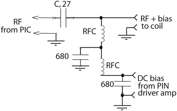
RF bias-Tee (two required) for adding PIN DC bias to RF line. The capacitance value of C is chosen to series-resonate the stray inductance of the RF path.
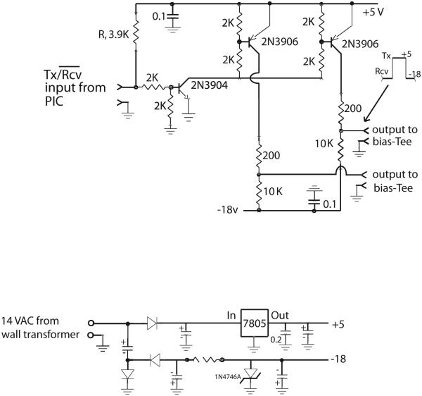
The PIN driver amplifier is built in a 10 cm × 10 cm cast aluminum box with a 14 VAC ‘wall adapter’ transformer fastened to its outside. This amplifier is powered by an ordinary 120 VAC extension cord, so that the PIN driver unit is stand-alone and does not need power from the spectrometer. The circuit in Figure 5 is straightforward, with two 2N3906 transistors providing two independent channels of output, to avoid the current-sharing issues associated with putting PIN diodes directly in parallel. The two outputs are in the same sense (i.e., both high or both low). The pull-up resistor R is a convenience for tuning the coil: an open input connector is pulled high by R, placing the unit in transmit mode. Shorting the input (or terminating it with 50 Ω) places the unit in receive mode. Thus, the transmit and receive coils can be tuned in their appropriate modes without requiring any control signal from the spectrometer. In operation, the TTL output of the spectrometer’s probe interface console (high on transmit, low on receive) easily overrides the pull-up resistor R.
Figure 5.
PIN driver amplifier accepts TTL input from the T/R switch and provides two separate outputs of +5 volts (current limited to 25 mA) during transmit to turn on each PIN diode and −18 volts during receive to turn off the PIN diodes. The power supply is shown below; it is powered by an AC adaptor wall transformer.
The power supply for the PIN driver amplifier also appears in Figure 5. A 3-pin analog regulator chip (7805) supplies +5 volts. A voltage doubler and shunt Zener diode provide regulated −18 volts. A combination of perforated-board and chassis wiring styles is used.
Results and Discussion
Both the transmit and receive coils have fairly narrow (e.g., 10 MHz) tuning ranges and one must, therefore, be careful in selecting fixed capacitors to properly tune these coils. We note that the PIN diodes will be off in the absence of bias, so the receiver coil can be tuned initially in this mode; for the transmitter, we shorted the PIN diode for initial tuning.
Our transmit coil has an inner diameter (ID) of 5.5 cm, large enough to accommodate the MR-compatible head holder used to secure the mouse, while still fitting into the 6.3-cm ID animal tray. The mouse is first secured in a prone position in the head holder using a pair of ear bars and a tooth bar, with its body oriented away from the holder. The entire assembly is then placed within the volume coil, with the mouse's head centered both top-to-bottom and front-to-back within the transmit coil. The volume coil's tuning components and coaxial cable connection fit conveniently into a groove cut on the underside of the head holder. The surface coil, a 1.6 cm ID coil formed from a single turn of wire, is centered directly over the mouse brain. A piece of Parafilm is placed atop the mouse's head to prevent the coil from contacting the head.
For each coil, we verified that its tuned frequency response shifted dramatically away from 200 MHz when the coil was biased to its inactive state. Placing the coils together with a mouse in the mouse holder, we confirmed that each coil, in its inactive mode, caused only minor de-tuning of the other, active coil. If both coils are active (by inappropriate bias voltage or current), coupling between the resonators is clearly evident on a frequency swept reflection bridge, unless the coils are within 2 or 3 degrees of being orthogonal to one another.
MR imaging data were collected in vivo from the brain of a 25 g Balb/C mouse placed in an Oxford Instruments (Oxford, UK) 4.7-Tesla magnet (40 cm, clear bore) equipped with 10-cm inner diameter, actively shielded gradient coils (maximum gradient, 50 G/cm; rise time, 200 μs). The magnet/gradients are interfaced with a Varian INOVA console and data were collected using the actively decoupled coil pair described here. Before the imaging experiments, the mouse was anesthetized with isoflurane and was maintained on isoflurane/O2 [1.25% (v/v)] throughout the experiments.
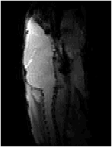
With a transmitter power of 10 watts (+40 dBm), the length of a rectangular pulse of 90 degrees nutation on the transmitter coil was ~85 μs. Figure 6 (a) shows a T1-weighted, gradient-echo image of a mouse brain (sagittal view); Figure 6 (b) is a panel of T2-weighted spin-echo images (transaxial view) of this same animal. The slice thickness on these transaxial images is 0.5 mm; the images are spaced 3 mm apart. Good coverage and high sensitivity across the entire brain are evident in these images. We now routinely use this coil arrangement for all of our mouse brain imaging experiments, including diffusion tensor work, with experiments extending over periods of up to three hours. We have also used this same coil arrangement for localized spectroscopy experiments using the LASER pulse sequence, where power of 400 watts (56 dBm) was used to generate the adiabatic π pulses required in this sequence.
Figure 6.
(a) Sagittal view, gradient-echo image of mouse brain collected in vivo using the actively decoupled coil pair. (b) Four slices, transaxial view, from a multi-slice, T2-weighted spin-echo of mouse brain in vivo. Slices are 0.5 mm thick and are separated from one another by 3 mm.
In summary, we have demonstrated the design, construction, and performance of a simple, inexpensive, platform-independent actively decoupled coil pair. PIN-diode switching provides excellent isolation between the larger transmit and smaller surface receive coils. The coils are mechanically and electrically stable and we seldom need to re-tune either coil when switching animals. While our initial applications have been in the imaging of brain, by simple repositioning of the mouse, this same coil pair can be used to study other organs and tissues that are near the surface of the mouse’s body. Straightforward scaling of these coils will permit the same design to be extended to rats and other rodents.
Footnotes
Prepared 30 July 2008 for submission to Magnetic Resonance Engineering
REFERENCES
- 1.Benveniste H, Ma Y, Dhawan J, Gifford A, Smith SD, Feinstein I, Du C, Grant SC, Hof PR. Anatomical and functional phenotyping of mice models of Alzheimer's disease by MR microscopy. Ann N Y Acad Sci. 2007;1097:12–29. doi: 10.1196/annals.1379.006. [DOI] [PubMed] [Google Scholar]
- 2.Jack CR, Jr., Marjanska M, Wengenack TM, Reyes DA, Curran GL, Lin J, Preboske GM, Poduslo JF, Garwood M. Magnetic resonance imaging of Alzheimer's pathology in the brains of living transgenic mice: a new tool in Alzheimer's disease research. Neuroscientist. 2007;13:38–48. doi: 10.1177/1073858406295610. [DOI] [PubMed] [Google Scholar]
- 3.Smith KD, Kallhoff V, Zheng H, Pautler RG. In vivo axonal transport rates decrease in a mouse model of Alzheimer's disease. Neuroimage. 2007;35:1401–1408. doi: 10.1016/j.neuroimage.2007.01.046. [DOI] [PMC free article] [PubMed] [Google Scholar]
- 4.Budde MD, Kim JH, Liang HF, Schmidt RE, Russell JH, Cross AH, Song SK. Toward accurate diagnosis of white matter pathology using diffusion tensor imaging. Magn Reson Med. 2007;57:688–695. doi: 10.1002/mrm.21200. [DOI] [PubMed] [Google Scholar]
- 5.Politi LS, Bacigaluppi M, Brambilla E, Cadioli M, Falini A, Comi G, Scotti G, Martino G, Pluchino S. Magnetic-resonance-based tracking and quantification of intravenously injected neural stem cell accumulation in the brains of mice with experimental multiple sclerosis. Stem Cells. 2007;25:2583–92. doi: 10.1634/stemcells.2007-0037. [DOI] [PubMed] [Google Scholar]
- 6.Sun SW, Liang HF, Schmidt RE, Cross AH, Song SK. Selective vulnerability of cerebral white matter in a murine model of multiple sclerosis detected using diffusion tensor imaging. Neurobiol Dis. 2007;28:30–38. doi: 10.1016/j.nbd.2007.06.011. [DOI] [PMC free article] [PubMed] [Google Scholar]
- 7.Banerjee D, Hegedus B, Gutmann DH, Garbow JR. Detection and measurement of neurofibromatosis-1 mouse optic glioma in vivo. NeuroImage. 2007;35:1434–1437. doi: 10.1016/j.neuroimage.2007.02.019. [DOI] [PMC free article] [PubMed] [Google Scholar]
- 8.Jost SC, Wanebo JE, Song SK, Chicoine MR, Rich KM, Woolsey TA, Lewis JS, Mach RH, Xu J, Garbow JR. In vivo imaging in a murine model of glioblastoma. Neurosurgery. 2007;60:360–370. doi: 10.1227/01.NEU.0000249264.80579.37. [DOI] [PubMed] [Google Scholar]
- 9.McConville P, Hambardzumyan D, Moody JB, Leopold WR, Kreger AR, Woolliscroft MJ, Rehemtulla A, Ross BD, Holland EC. Magnetic resonance imaging determination of tumor grade and early response to temozolomide in a genetically engineered mouse model of glioma. Clin Cancer Res. 2007;13:2897–2904. doi: 10.1158/1078-0432.CCR-06-3058. [DOI] [PubMed] [Google Scholar]
- 10.Kim JH, Budde MD, Liang HF, Klein RS, Russell JH, Cross AH, Song SK. Detecting axon damage in spinal cord from a mouse model of multiple sclerosis. Neurobiol Dis. 2006;21:626–32. doi: 10.1016/j.nbd.2005.09.009. [DOI] [PubMed] [Google Scholar]
- 11.Loy DN, Kim JH, Xie M, Schmidt RE, Trinkaus K, Song SK. Diffusion tensor imaging predicts hyperacute spinal cord injury severity. J Neurotrauma. 2007;24:979–990. doi: 10.1089/neu.2006.0253. [DOI] [PubMed] [Google Scholar]
- 12.Ugurbil K, Garwood M, Bendall M. Amplitide- and frequency-modulated pulses to achieve 90-degree plane rotations with inhomogeneous B1 fields. J Magn Reson. 1987;72:177–185. [Google Scholar]
- 13.Bendall M, Garwood M, Ugurbil K, Pegg D. Adiabatic refocusing pulse which compensates for variable RF power and off-resonance effects. Magn Reson Med. 1988;4:433–499. doi: 10.1002/mrm.1910040510. [DOI] [PubMed] [Google Scholar]
- 14.Ugurbil K, Garwood M, Rath A, Bendall M. Amplitude- and frequency/phase-modulated refocusing pulses that induce plane rotations even in the presence of inhomogeneous B1 fields. J Magn Reson. 1988;78:472–497. [Google Scholar]
- 15.Avdievich N, Hetherington H. A 4T actively detunable transmit/receive 1H transverse electromagnetic (TEM) and 4-channel receive-only phased array coil for 1H human brain studies. Magn Reson Med. 2004;52:1459–1464. doi: 10.1002/mrm.20264. [DOI] [PubMed] [Google Scholar]
- 16.Baberi E, Gati J, Rutt B, Menon R. A transmit-only/receive-only (TORO) RF system for high-field MRI/MRS applications. Magn Reson Med. 2000;43:284–289. doi: 10.1002/(sici)1522-2594(200002)43:2<284::aid-mrm16>3.0.co;2-c. [DOI] [PubMed] [Google Scholar]
- 17.Doty F, Entzminger G, Kulkarni J, Li L, Staab J. RF coil technology for small-animal MRI. NMR in Biomedicine. 2007;20:304–325. doi: 10.1002/nbm.1149. [DOI] [PubMed] [Google Scholar]
- 18.Mispelter J, Lupu M. NMR probeheads for biophysical and biomedical experiments. Theoretical principles & practical considerations. Imperial College Press; London: 2006. pp. 488–491. A B. [Google Scholar]
- 19.Pop-Fanea L, Valkespin S, Hutchinson J, Forrester J, Seton H, Forster M, Liversidge J. Evaluation of MRI for in vivo monitoring of retinal damage and detachment in experimental occular inflammation. Magn Reson Med. 2005;53:61–68. doi: 10.1002/mrm.20326. [DOI] [PubMed] [Google Scholar]
- 20.Quick H, Serfaty J-M, Pannu H, Genadry R, Yeung C, Atalar E. Endourethral MRI. Magn Reson Med. 2001;45:138–146. doi: 10.1002/1522-2594(200101)45:1<138::aid-mrm1018>3.0.co;2-g. [DOI] [PubMed] [Google Scholar]
- 21.Alderman D, Grant D. An efficient decoupler coil design which reduces heating in conductive samples in superconducting spectrometers. J Magn Reson. 1979;36:447–451. [Google Scholar]
- 22.Pozar D. Microwave Engineering. Addison-Wesley; Reading: 1990. pp. 177–190. [Google Scholar]


