Abstract
Objective
Ventricular assist device (VAD) miniaturization is one design trend that may result in less-invasive implantation techniques and more versatility with patient selection. The MVAD System is a miniature, continuous-flow device implanted in the ventricle. The pump is capable of delivering between 0 and 7 L/min of flow at a mean arterial pressure of 75 mm Hg. The impeller was optimized from its original design to improve hydraulic performance, minimize shear regions, and enhance the impeller’s radial stiffness. These studies evaluated the MVAD System with modified impeller in the preclinical setting.
Methods
This modified pump design was tested through chronic studies (n = 6) in a healthy ovine model where 4 animals were implanted for a duration of 30 ± 5 days and 2 animals were implanted for a duration of 90 ± 5 days. The pump was placed in the left ventricular apex with the outflow graft anastomosed to the descending aorta. Postoperatively, no anticoagulant or antiplatelet therapies were administered throughout the study duration.
Results
All 6 animals reached their elective date of kill, demonstrating no evidence of organ compromise or device-related complications. Average pump parameters did not deviate significantly, and average rotational speed, pump flow, and power consumption were 14095 ± 139 RPM, 4.1 ± 0.4 L/min, and 4.3 ± 0.1 W, respectively. Examination of pump components postexplant demonstrated no mechanical wear or thrombus formation.
Conclusions
Hemocompatibility and biocompatibility of the modified MVAD System were demonstrated through pump parameters, blood chemistry panels, and histopathology analysis.
Key Words: MVAD, Miniaturization, LVAD, HeartWare, Congestive heart failure
Over the past 10 years, ventricular assist devices (VADs) have gained increased acceptance as a treatment therapy for advanced stages of heart failure. Continuous-flow VADs have become the gold standard, with over 4000 patients enrolled into the Interagency Registry for Mechanical Assisted Circulatory Support (INTERMACS).1 In the past, device reliability and device-related adverse events inhibited adoption of long-term mechanical circulatory support. However, current advances in VAD technology have improved patient outcomes, and the 2-year survival rate with continuous-flow VADS for destination therapy patients is 70%.1 As long-term support becomes more prevalent, next-generation devices must not only enable wider application of the therapy but also enhance patient quality of life.
Ventricular assist device miniaturization may offer several important benefits. By reducing the required thoracic space and pump footprint, patients with a smaller body habitus (<1.2 m2) may become candidates for device implantation.2 A miniature device may also promote minimally invasive surgical techniques that reduce the surgical trauma associated with sternotomy and cardiopulmonary bypass, resulting in lower associated adverse events and faster recovery times.3 The MVAD pump does not require the creation of a pump pocket, which may reduce invasiveness of surgery, length of stay, and complications such as bleeding, hematoma, and infections. In addition, device miniaturization and ease of implantation may ultimately lead to a paradigm shift in clinical practice, resulting in the treatment of a less ill cohort of patients.4
The MVAD System is a miniature VAD designed to provide circulatory assistance to patients diagnosed with end-stage, refractory heart failure. The pump size is significantly smaller than devices currently on the US market with a displacement volume of 20 mL and a weight of just 78 g. In comparison, the Thoratec HeartMate II Pump and HVAD Pump weigh 290 and 160 g, respectively.5,6 A size comparison of the HVAD Pump and MVAD Pump are shown in Figure 1. In addition, the MVAD System peripheral equipment was designed after extensive field research with patients, caregivers, emergency responders, VAD coordinators, cardiologists, and surgeons. Usability and human factor testing were conducted to determine the most ergonomic, safe, and intuitive design. Miniaturization of the pump design as well as simplification of the user experience through user-friendly patient peripherals are 2 important steps toward improving patient quality of life.
FIGURE 1.
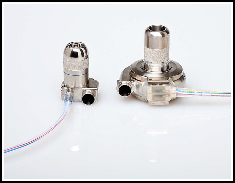
Size comparison of the MVAD Pump—The HeartWare HVAD Pump (right) weighs 160 g compared with the MVAD Pump (left), which weighs 78 g.
SYSTEM DESCRIPTION
Implantable System Components
Overview
The MVAD Pump is a miniature axial flow pump with a displacement volume of 20 mL and a weight of 78 g. The pump’s small size and short integrated inflow cannula allow for pericardial placement, similar to its predecessor, the centrifugal HVAD Pump. The sewing ring, which is composed of a titanium frame surrounded by a polyester felt ring, is sutured to the ventricular apex and secures the pump to the myocardium. In additional, the sewing ring was designed with a polymer gimbal feature that creates a ball-and-socket joint, allowing for intraoperative depth and angle adjustments to obtain optimal inflow cannula positioning. The gel-impregnated 10 mm polyester outflow graft with strain relief connects the MVAD Pump to the arterial system via end-to-side anastomosis. An image of the implanted pump is shown in Figure 2. A thin, flexible driveline (diameter = 3.5 mm, length = 70 cm) is tunneled percutaneously and exits from the patient’s abdominal wall. The driveline is composed of 3 wires encapsulated in extruded silicone with a polyurethane outer sheath. A portion of the driveline is covered by an additional polyester velour sleeve that promotes wound healing at the exit site.
FIGURE 2.
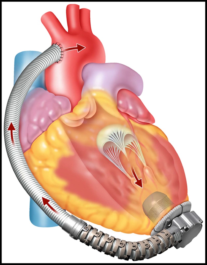
The implanted MVAD Pump—The pump inflow cannula is inserted into the left ventricle apex and the outflow graft is anastomosed to the arterial system.
The MVAD Pump has 1 moving part—a wide bladed, platinum alloy impeller suspended inside a ceramic tube. This impeller operates through a wearless, hybrid suspension system that employs both passive magnetic and hydrodynamic forces. The magnetic interaction between the stator and the impeller provides axial stiffness, while 8 hydrodynamic thrust bearings on the impeller surface produce the radial forces required to hydraulically suspend the impeller inside the titanium tube. The design of the motor stator geometry has been matched to the magnetic signatures of the impeller to achieve optimal motor efficiency while maintaining the desired axial stiffness.
There are 2 flow paths through the MVAD Pump. In the primary flow path, blood enters the inflow cannula, moves through the impeller flow channels, and exits the pump through the outflow port into the outflow graft. In the secondary flow path, blood flows across the gap between the impeller and the ceramic tube creating hydrodynamic radial thrust bearings (Fig. 3).
FIGURE 3.
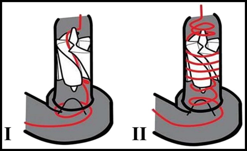
Flow paths through the MVAD Pump—Primary (I) and secondary (II) flow paths through the MVAD Pump are shown.
Impeller rotation is achieved by a sensorless brushless motor driver that is located within the titanium pump housing. The motor driver consists of 3 coils, which are energized sequentially to generate the force necessary to rotate the impeller. The commutation scheme drives 2 of the 3 stator coils at 1 time: 1 coil driven high to push the impeller and 1 coil driven low to pull the impeller. The third coil is placed in a high-impendence state to measure back electromotive force, which is a key parameter in several motor control and physiologic control algorithms. The rotating impeller generates pump pressure head, pushing blood from the inlet (ventricle) to the outlet (arterial system). Rotational speed for the MVAD Pump ranges between 8000 to 18,000 RPM, and it is capable of delivering blood flow of 1 to 7 L/min at 75 mm Hg mean arterial pressure.
In 2013, the impeller was optimized in order to enhance its radial stiffness as well as to improve pump hydraulic performance and minimize shear regions. Changes to the impeller design included modifications to the blade discharge angle as well as flow channel width to enhance device performance. In addition, the blade design was modified with a trim at the front end and an added scoop feature at the rear end to reduce shear stress and improve hemocompatibility. Based on in vitro studies, shear stress as reflected by hemolysis levels, were reduced significantly versus the original impeller geometry. Finally, alterations on the front-to-rear thrust bearing surface area ratio and the thrust bearing pocket depth were made to improve radial stiffness.
External System Components
Extensive field research was performed to design a user-intuitive peripheral system. Design goals aimed to (1) reduce the number of battery interactions, (2) make the act of connecting and disconnecting batteries easier, (3) ensure a reasonable battery safety cushion, (4) provide a method to recharge batteries away from home, (5) help protect driveline integrity and minimize trauma at the percutaneous exit site, (6) provide useful system status information to the patient and support active problem solving, (7) allow patients to look at individual indicators for power, VAD information, and system health, (8) minimize system weight and number of components, and (9) create equipment and carrying methods that reduce bulkiness.
Peripheral System Description
The percutaneous driveline connects the pump to the Pal Controller using an integrated, pigtail driveline cable. This pigtail feature was designed to absorb the stresses and strains placed on the driveline exit site and mitigate damage to system components. The Pal Controller is a wearable, water-resistant, and ergonomically designed microprocessor [dimensions, 9.6 × 4.8 × 8.4 cm; weight, 0.38 kg (without pigtail driveline) and 0.43 kg (with pigtail driveline)], which regulates pump function and monitors the VAD system, providing audible, visual, and vibratory alerts regarding system status and troubleshooting tips. The user interface is a touchscreen, monochrome LCD with colored backlight reflecting system status (blue, normal; yellow, noncritical alarm; red, critical alarm). The main controller screen is called the Home screen and displays pump and power status with battery runtime shown in hours and minutes. The touchscreen allows patients to navigate the controller menu to 4 possible screens from the Home screen: VAD Status, System, Information, and Alarm History. These screens provide information regarding VAD parameters, active and inactive alarms, battery and controller status, battery charging status, and action required by the patient.
The controller contains an internal lithium ion battery that can power the system for up to 45 minutes. This enables continuous pump function while power sources are being changed. The controller’s internal battery will automatically recharge when an external power source is attached. AC or DC power adapters may be connected to the controller when patients are not ambulatory. When the controller is connected to AC or DC power, an attached external battery will automatically recharge. For portable use, the system has 2 rechargeable, lithium ion battery options, which clip onto the bottom of the controller by a cableless interface to form an integrated unit. These batteries are capable of providing up to 5 hours (dimensions, 9.6 × 7.6 × 4.8 cm; weight, 0.34 kg) and 10 hours (dimensions, 9.6 × 11.5 × 4.8 cm; weight, 0.5 kg) of support.
The Pal Controller connects to the monitor via a USB cable. The monitor is password protected and permits clinicians to change settings such as patient ID, pump speed, alarm limits, hematocrit settings, and algorithm settings. The monitor also allows clinicians to view real-time VAD parameters (pump speed, power consumption, and estimated VAD flow) on the Clinical screen and long-term data on the Trend screen. The Pal Controller records average VAD parameters once every 10 minutes and can store up to 30 days of data in a first-in, first-out file format. These VAD parameter log files are automatically transmitted to the monitor when the controller is connected. The clinician is able to retrieve these logs with a USB device and e-mail the data to HeartWare clinical engineers for a comprehensive review of pump operation.7 The MVAD System is depicted in Figure 4.
FIGURE 4.
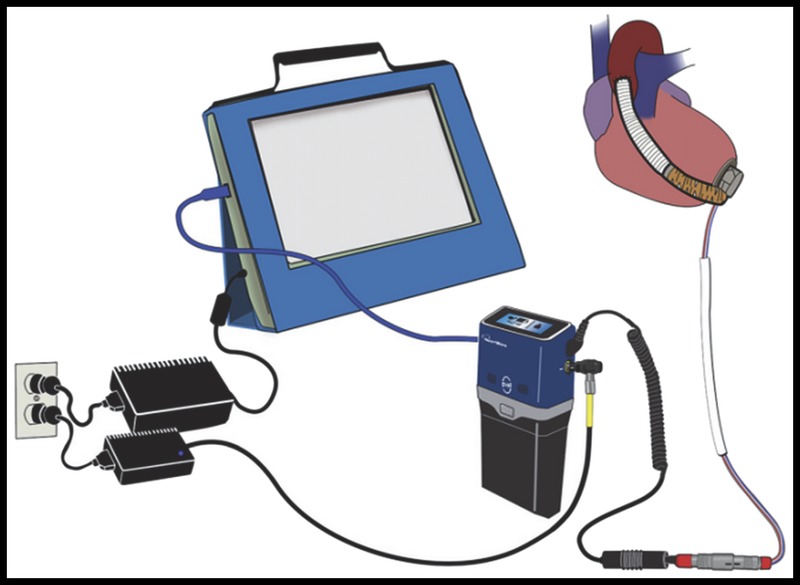
MVAD System components—The pump, controller, battery, controller AC power, and monitor are shown.
CONTROLLER ALGORITHMS
The Pal Controller was designed with several active and passive physiological control algorithms (PCAs), which derive hemodynamic indicators, detect and respond to ventricular suction episodes, and may promote aortic valve function. Passive PCAs do not alter device operation, whereas active PCAs are capable of bounded speed control functionality. In this system, passive PCAs include flow estimation and suction detection, while active PCAs include suction response, pump pressure response, and the qPulse Cycle. These algorithms are discussed subsequently.
Flow Estimation
The MVAD Pump demonstrates a nonlinear relationship between power consumption and pump flow. Because of this nonlinearity, a novel algorithm for pump flow estimation was developed. This passive PCA calculates pump flow using motor current and back electromotive force in combination with static relationship tables from a set of performance curves. In addition, the flow estimation algorithm relies on patient hematocrit, which is manually measured and entered by the clinician. The valid range of estimated MVAD Pump average blood flow is 1 to 7 L/min.
Suction Detection and Response
Suction can occur as a result of intermittent or sustained occlusions of the pump inflow cannula by either the interventricular septum or ventricular free wall. Sustained suction may cause arrhythmias or damage to the myocardium or even lead to ventricular collapse.8,9 The MVAD Pump’s suction detection algorithm functions by monitoring VAD parameters for changes indicative of sudden decreases in flow rate. The suction algorithm has 3 possible states: disabled, enabled to alarm the patient, or enabled to both alarm the patient and respond to the detected suction event by decreasing VAD speed to the lower of 14,000 RPM or 15%, with a subsequent slow speed increase back to the set point. Once the speed returns to the set point, a reassessment of the suction condition is performed. If the suction condition has resolved, the algorithm will shut off. If the suction condition persists, the next sequence is initiated with a 25% decrease in VAD speed with a subsequent slow speed increase back to the set point. This cycle will continue for as long as the suction condition persists.
Pump Pressure Algorithm
The pump pressure algorithm (PPA) is an active PCA designed to prevent large pressure buildup across the MVAD Pump, which may occur as the result of a pump inflow or outflow occlusion. These conditions can occur as a result of the pump’s ability to generate high pressures when operating at high speeds during low flow conditions. When the pump pressure condition (large pressure buildup across the pump) is detected, the controller will decrease the speed to a predetermined level and maintain this speed until the estimated flow recovers to a predetermined flow recovery value, indicating that the high pressure condition has cleared.
qPulse Cycle
The qPulse Cycle is an active algorithm that intermittently reduces pump speed from its set point. The purpose of this algorithm is to temporarily reduce VAD support and increase the probability that the native heart may eject through the aortic valve. The qPulse Cycle consists of a 5-second decrease in pump speed (either by 15% or 20%) followed by a return to the set speed (either for 10 or 30 seconds).
IN VIVO TESTING
Methodology
Six animals were implanted with the MVAD Pump without the use of cardiopulmonary bypass. For each case, after induction of general anesthesia, the animal was placed in the right lateral recumbency position, and a left thoracotomy was performed at the fifth intercostal space. The ribs were retracted for adequate exposure of the heart, and the pericardium was incised. The descending aorta was isolated, and an end-to-side anastomosis was performed with the 10-mm outflow graft. The heart was elevated from the chest for visualization and placement of the gimbaled sewing ring onto the left ventricular apex. A cruciate incision was performed within the confines of the sewing ring, and the ventricle was cored with the apical coring tool. The pump was then inserted into the sewing ring, and the inflow cannula angle was adjusted using the gimbal positioner and was secured. The outflow graft was de-aired with an 18G needle, and the pump was actuated. A flow probe (Transonic, Ithaca, NY USA) was placed on the outflow graft. Both the pump driveline and flow probe cable were tunneled subcutaneously to a 2-cm incision at the dorsal aspect of the thoracic incision near the spine. No anticoagulant or antiplatelet therapies were administered postoperatively. Blood chemistry panels were collected weekly, and pump parameters (speed, power consumption, and pump flow) were collected hourly throughout the course of the study. The animal was euthanized at the study’s scheduled end point of 30 or 90 days. Gross necropsy and histopathology examinations were performed on all subjects. In addition, pumps were disassembled and examined for evidence of mechanical wear and signs of thrombosis.
Results
All 6 animals survived to their scheduled explant without device-related issues or evidence of end-organ compromise. Throughout the study period, no significant changes in pump parameters were observed. Average pump speed, pump flow, and power consumption were 14095 ± 139 RPM, 4.1 ± 0.4 L/min, and 4.3 ± 0.1 W, respectively (Fig. 5).
FIGURE 5.
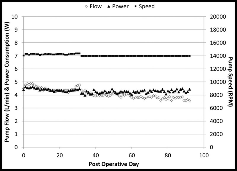
VAD parameters for chronic studies—Average pump parameters for 6 animals are shown (average speed, 14095 ± 139 RPM; average pump flow, 4.1 ± 0.4 LPM; and average power consumption, 4.3 ± 0.1 W).
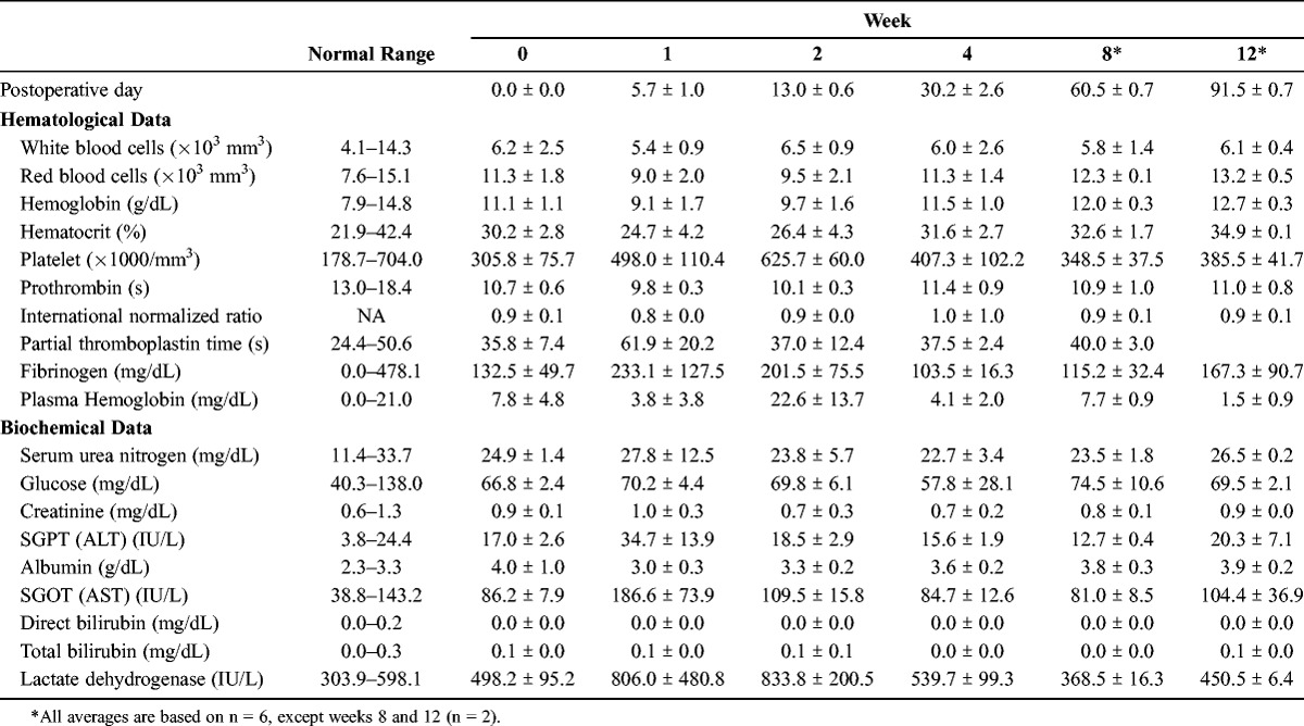
Hematological and biochemical results are shown in Table 1. A decrease in hematocrit was observed in 1 sheep on the first postoperative day, which required 2 transfusions and resulted in a temporary increase in plasma free hemoglobin (PFHG) and lactate dehydrogenase (LDH) due to a delayed hemolytic transfusion reaction. An increase in PFHG was observed in 4 sheep during the second postoperative week. Pump parameters remained unchanged throughout this period, and PFHG and LDH returned to normal limits by the time of explant without pharmacological intervention. Average PFHG and LDH were within normal limits at postoperative day 30 with an average value of 4.1 ± 2.0 mg/dL and 539.7 ± 99.3 IU/L, respectively.
TABLE 1.
Average Total Blood Counts and Serum Analytes—Measured Blood Parameters Are Shown Over the Course of the Study Duration
Gross examination and histopathologic analysis of the pump postmortem revealed that the device performed as expected in this animal model. The percutaneous driveline and flow probe entry site and subcutaneous tract were well healed using fibrous integration with no exudate or evidence of infection. A fibrous capsule developed around the device and appeared normal, pale, and noninflammatory with a smooth contact surface. The pump was well centered in the left ventricular chamber in all cases. Areas of chronic ischemic infarction were noted surrounding the sewing ring, and in some cases, this area extended into the interventricular septum and also into the right ventricular free wall. There was a smooth transition from the endocardium to the device interface. A thin layer of mature, fibrocellular neoendicardium extended over the entire sintered surface of the inflow conduit. In all cases, the interior of the outflow graft and anastomosis site were clear and patent. Small renal infarcts (<0.5 mm) were observed in 4 of the 6 animals. These renal infarcts likely occurred in the intraoperative period and are commonly seen with this animal model and surgical implantation technique. Other end organs, including the brain, liver, and spleen, were normal in all cases. In the animal that received the blood transfusions, a hematoma was identified in the dorsal aspect of the thoracic cavity, surrounding the outflow graft-aorta anastomosis and extending along the left-side length of the thoracic aorta. In all animals, all disassembled pump components were carefully examined. Neither evidence of mechanical wear nor thrombus formations were identified (Fig. 6).
FIGURE 6.
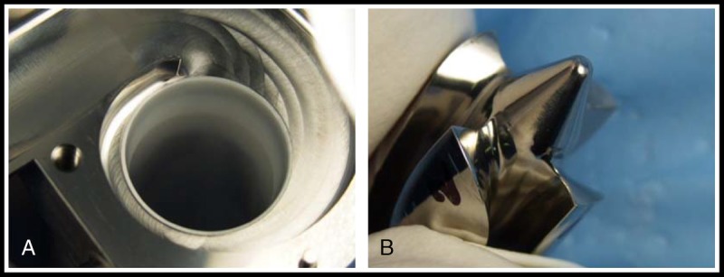
Pump components postexplant—A, Upper housing of pump. B, Rear cone view of impeller and impeller blade from the animal implanted 32 days.
CONCLUSIONS
The MVAD System is the first in a series of miniature HeartWare pumps based on the MVAD technology platform. These miniaturized devices may reduce surgical trauma and thus minimize the adverse events associated with device implantation. Reduced transfusion rate, early mobilization, and shorter recovery time are expected. In addition, a smaller platform may reduce the complexity of the reoperation for cardiac transplantation and/or explantation. Patient quality of life is also anticipated to improve, with peripheral component design of the system centered on enhancing the patient experience through lighter, more ergonomic, and intuitive components. Chronic studies conducted in an ovine model with study durations of 30 ± 5 and 90 ± 5 days demonstrated excellent biocompatibility and hemocompatibility as shown through pump parameters, blood chemistry panels, and histopathology analysis. One sheep required 2 transfusions on the first postoperative day, which resulted in a temporary increase in PFHG and LDH due to a delayed hemolytic transfusion reaction. This event was non-device-related as shown by the pump parameters, which remained unchanged throughout the study period, as well as PFHG and LDH, which returned to normal limits by the time of explant. The availability of this miniaturized VAD may revolutionize the care of heart failure patients and expand the treatment cohort.
CLINICAL PERSPECTIVE
The use of ventricular assist devices (VADs) in the management of end-stage heart failure has increased exponentially during the last decade, revolutionizing the treatment of these patients. However, there are still considerable morbidity and mortality associated with VAD implantation. This study was a preclinical evaluation of a miniaturized VAD system. The pump was capable of delivering up to 7 L/min of flow at a mean arterial pressure of 75 mm Hg. This pump was tested in a chronic sheep model. The pump was placed in the left ventricular apex with the outflow graft anastomosis on the descending aorta. No anticoagulation or antiplatelet therapy was administered. Four animals were survived for 30 days and two for 90 days. There was no evidence of pump failure or thrombosis. None of the animals had any evidence of organ compromise or device-related complication. The system had excellent hemocompatibility and biocompatibility.
This excellent study from Dr Cheung and his colleagues at the University of British Columbia demonstrated excellent results with this miniaturized VAD system. It is hoped that this next-generation VAD may not only reduce surgical trauma but also minimize the vexing complications after device implantation, including bleeding and stroke. These are exciting preliminary results, and clinical trials are eagerly anticipated.
Footnotes
Presented at the Annual Scientific Meeting of the International Society for Minimally Invasive Cardiothoracic Surgery, June 12–15, 2013, Prague, Czech Republic.
Disclosures: Anson Cheung, MD, is a consultant to HeartWare, Inc., Miami Lakes, FL USA. Katherine Chorpenning, MS, Daniel Tamez, BS, Charles Shambaugh, Jr, BS, Anne E. Dierlam, BS, M. Ertan Taskin, PhD, Michael Ashenuga, MBA, Carlos Reyes, MS, Jeffrey A. LaRose, MS, are current employees of HeartWare, Inc., Miami Lakes, FL USA.
REFERENCES
- 1. Kirklin JK, Naftel DC, Kormos RL, et al. The Fourth INTERMACS Annual Report: 4000 implants and counting. J Heart Lung Transplant. 2012; 31: 117– 126. [DOI] [PubMed] [Google Scholar]
- 2. Miera O, Potapov EV, Redlin M, et al. First experiences with the HeartWare Ventricular Assist System in children. Ann Thorac Surg. 2011; 91: 1256– 1260. [DOI] [PubMed] [Google Scholar]
- 3. Garbade J, Bittner HB, Lehmann S, Mohr FW, Barten MJ. Miniaturization of left ventricular devices: the ongoing trend. Expert Rev Med Devices. 2012; 9: 49– 58. [DOI] [PubMed] [Google Scholar]
- 4. Giridharan GA, Lee TJ, Ising M, et al. Miniaturization of mechanical circulatory support systems. Artif Organs. 2012; 36: 731– 739. [DOI] [PMC free article] [PubMed] [Google Scholar]
- 5. Sheikh FH, Russell SD. HeartMate II continuous-flow left ventricular assist system. Expert Rev Med Devices. 2011; 8: 11– 21. [DOI] [PubMed] [Google Scholar]
- 6. LaRose JA, Tamez D, Ashenuga M, Reyes C. Design concepts and principle of operation of the HeartWare ventricular assist system. ASAIO J. 2010; 56: 285– 289. [DOI] [PubMed] [Google Scholar]
- 7. Chorpenning K, Brown MC, Voskoboynikov N, et al. HeartWare Controller Logs: A diagnostic tool and clinical management aid for the HVAD Pump. ASAIO J. 2013; 60: 115– 118. [DOI] [PubMed] [Google Scholar]
- 8. Vollkron M, Schima H, Huber L, Benkowski R, Morello G, Wieselthaler G. Development of a suction detection system for axial blood pumps. Artif Organs. 2004; 28: 709– 716. [DOI] [PubMed] [Google Scholar]
- 9. Yildirim Y, Pecha S, Reichenspruner H, Deuse T. Mechanically induced ventricular tachycardia by the HeartWare ventricular assist device. ASAIO J. 2014; 60: 124– 126. [DOI] [PubMed] [Google Scholar]


