Abstract
Position localization is essential for visually impaired individuals to live independently. Comparing with outdoor environment in which the global positioning system (GPS) can be utilized, indoor positioning is more difficult due to the absence of the GPS signal and complex or unfamiliar building structure. In this paper, a novel landmark-based assistive system is presented for indoor positioning. Our preliminary tests in several buildings indicate that this system can provide accurate indoor location information.
Keywords: Wearable computer, indoor positioning, blind and visually impairment, navigation
I. Introduction
According to the report of Center for Disease Control and Prevention published in 2008, there are about 39 million people suffering from blindness and 246 million with low vision worldwide [1]. These people often rely on a cane or a guide dog to find their ways [2]. Although these aids are helpful, they often face major challenges in localizing themselves, especially in an unfamiliar indoor environment.
In order to solve this problem, researchers have investigated various methods to assist the blind and visually impaired. Wireless networks such as the cellular network [2] and WiFi [3] have been used for indoor localization. However, the accuracy of these methods is relatively low due to complex reflections of electromagnetic waves within a building. Although active methods using Bluetooth [4] or radio frequency identification (RFID) [5] can improve accuracy, pre-installed infrastructures are required, which are expensive. Image-based positioning methods have also been studied without expensive infrastructure installation [6]. However, the user must hold a smartphone and point it to a set of specifically designed printed signs, such as wall mounted bar codes, for scanning location information, which is a difficult task for the individuals with visual impairments. In this paper, we present a wearable assistive device and a landmark-based image processing method for indoor positioning. Experimental results indicate that our device and method are convenient and inexpensive, yet providing a high accuracy for indoor positioning and localization.
II. Methods
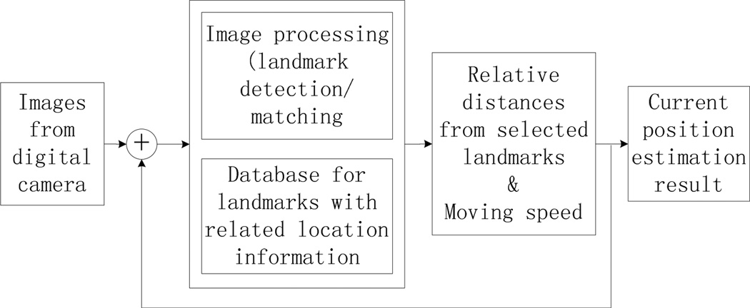
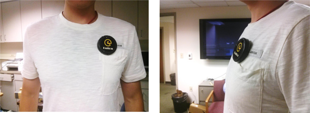
The function blocks of our landmark-based system for indoor positioning are highlighted in Fig. 1. A self-constructed wearable computer called eButton [7] is used to obtain a continuous sequence of images. The device can be conveniently worn on the chest (Fig. 2). A camera inside eButton can automatically capture images in front of the wearer at a pre-defined speed (e.g, one picture in several seconds). Once a new image is captured, it is processed by our algorithm to find natural landmarks for the building from a pre-established database, which stores reference landmarks of the building along with the location information (e.g., floor level and nearest room numbers). The position information is obtained from this database and provided to the wearer in synthesized voice.
Fig. 1.
Function blocks of the indoor positioning system
Fig. 2.
Wearable computer (eButton) used for indoor positioning
A. Database construction
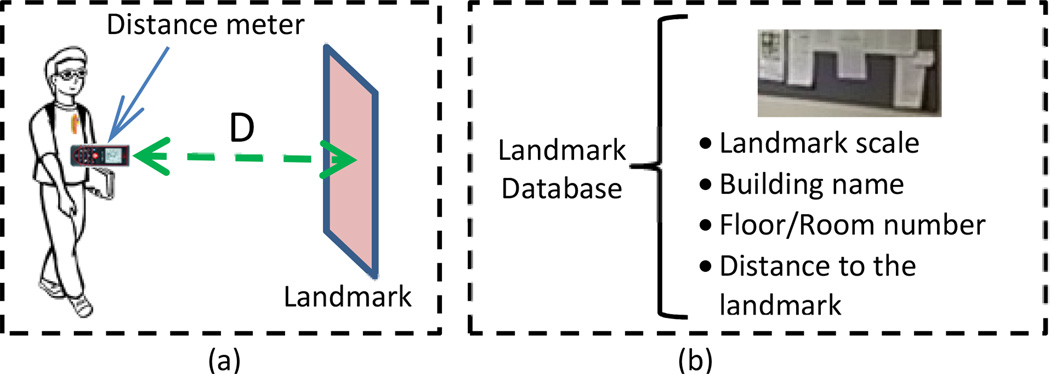
A pre-constructed landmark database is required in our system. The construction procedure is illustrated in Fig. 3. First, an individual with a normal vision walks along the center of the hallway with an eButton attached on his/her chest. The image sequence of the hallway is automatically acquired by eButton as the person walks. A laser distance meter is utilized to measure the actual distance (D in Fig. 3) between the current location and one selected landmark. The location information, such as the floor level, distance to landmark, room number, and the scale ratio between the size of the landmark and the size of original image are stored in the database along with the image sequence.
Fig. 3.
(a) Procedure to Diagram of database establish database procedure; (b) main components in in the landmark database
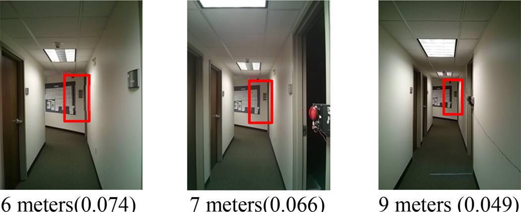
Although it is possible to select landmarks automatically, our experience indicates that a manual selection is more reliable. Candidates for selection include certain corners, distinct decorative features, doors, elevators and stair wells. Examples of selected landmarks are shown in Fig. 4 marked with red frames.
Fig. 4.
Manual landmark selection examples. This landmark is included in these reference images captured from different distances, as shown in the label under each picture. The calculated scale of each image is listed in the parentheses.
B. Position localization based on landmark recognition and motion estimation
When the blind or visually impaired person walks along the same hallway which has an entry in the established database, our indoor positioning algorithm is implemented. Our algorithm is highlighted in Fig. 5. It contains two major components, feature extraction/landmark matching and motion estimation for the final indoor positioning localization.
Fig. 5.
landmark matching algorithm position localization
1) Landmark recognition
In real applications, images of the same location are different from time to time due to the walking activity. Therefore, the scale-invariant feature transform (SIFT) image feature descriptor [8] is utilized for extracting features from the input image and matching them with reference landmarks in the database. The extraction of SIFT features includes localizing key points in the input image, determining their orientation, and creating a descriptor for each key point.
Positions of key points are located by scale-space extrema in the difference-of-Gaussian (DOG) function. Local maxima and minima of DOG are selected as the candidates of key points. A 128-dimensional vector containing orientation information is calculated as the descriptor within one 16 × 16 neighborhood of the key point [8].
Fig. 6 shows the detected SIFT features of the selected landmark in different scales in one section of hallway. Fig. 6 (a) shows the feature points of a selected landmark from (b) captured six meters away from the landmark. Panels (b)–(f) show the feature points of the landmark within images captured from different distances.
Fig. 6.
SIFT feature of a selected landmark with different scales in one image sequence. (a) Selected landmark with SIFT feature points labeled as green spots. (b–f) Images that contain the selected landmark captured between 6 and 10 meters with one-meter interval.
For each new image captured by the eButton, SIFT features are extracted and used to match the reference landmark images. Fig. 7 (a–e) show the SIFT feature based matching results of Fig. 6(a) and Fig. 6(b–f). Since the selected landmark is linked with its location information in the database, the matching result with same scale of the captured image is used to indicate the blind person’s location.
Fig. 7.
SIFT matching results from Fig. 6 (a) and Fig.6 (b–f) respectively
2) Motion estimation and position localization
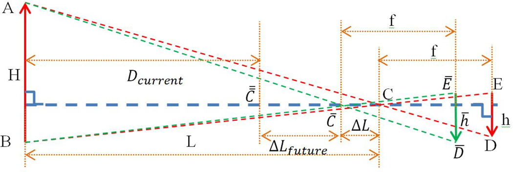
In order to save computation, landmark matching is performed only sparsely. There is a need to smooth the localization results in time and space. We thus calculate motion information based on the pinhole camera model to implement this smoothing process. Fig. 8 shows the relationships among a group of related variables. From the homologous triangles (ΔABC and ΔCDE), we have
| (1) |
where L and f are the heights of triangles ΔABC and ΔCDE, is the height of the target in the real world coordinate system, H is pre-measured and stored in the database, is the size of the target (h) in the image, C is one of the reference positions stored in the database, C̄ is the location between the two reference locations, L is the distance from the camera to the target, and f is the focal length of the digital camera in the eButtton.
Fig. 8.
Position localization based on the pinhole model of the camera and landmark matching
According the homologous triangles ΔABC̄ and Δ C̄D̄Ē, the distance from C̄ to the landmark (L − ΔL) can be calculated by
| (2) |
where h̄ is the size of the target in the new image from C̄ and ΔL is the traveled distance which can be calculated from Eq. (1) and Eq. (2).
| (3) |
The estimation of the moving speed νest can be obtained based on the time interval Δt
| (4) |
The moving distance ΔLfuture in the next time interval Δtfuture which is the distance from C̄ to C̿ is given by
| (5) |
Once the new traveling distance is calculated by Eq. (5), the relative distance Dcurrent is obtained from the current location C̿ to the landmark:
| (6) |
The calculated relative distance Dcurrent by Eq. (6) is the distance from location C̿ to the selected reference landmark as shown in Fig. 8. As the reference landmark has been registered in the database with location information, Dcurrent can be used to determine the blind person’s location in reference to the registered landmark.
III. Experiment & results
To evaluate our algorithm, two experiments were conducted for both motion estimation and position localization. Three subjects were asked to take tests in three selected hallways, which all have the same length (15 meters). The databases of the three hallways have been established before the tests by asking another person to walk through the hallways while wearing the eButton. Images of landmarks captured at positions 6, 8 and 10 meters are stored in the database as reference images. One landmark was selected for each hallway and SIFT features of each landmark were extracted and saved in the database. A measurement platform was designed to obtain the ground truth values of the distances. Results from our algorithm are compared to the ground truth for algorithm evaluation.
A. Ground Truth Value Acquisition
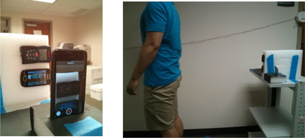
A laser distance meter and a stop watch based platform, which is shown in Fig. 9, was used to obtain the ground truth data. During each experiment, the subject stands in front of the laser distance meter with laser pointing at him/her clothing to measure the distance between subject and measurement platform during walking. The stop watch was used to measure the travel time. The average walking speed 03BDground truth is calculated by
| (7) |
where ΔLground truth is the traveled distance from the distance meter, and Δt is the traveling time.
Fig. 9.
Algorithm evaluation platform
The ground truth value for the distance between the reference point and walker’s location was also provided by the distance meter.
B. Experiment to validate moving speed
In this experiment, each subject was asked to walk at their own pace twenty times in each of the three hallways. The average speed between the 6-meter position and the 10-meter position was computed to be the ground truth using Eq. (7). The estimated moving speed was calculated using Eq. (4) after finding the matched landmark of these two positions in the acquired images and calculating the scales. Fig. 10 shows the comparison between the estimated moving speed and the ground truth for one subject in the 20 walking trials. According to the results, the maximum absolute error is only 0.0643 m/s. The root-mean-square (RMS) errors of the estimation are listed in Table 1. A paired t-test for each subject’s data was conducted. In all three cases, the results show that there is no significant difference between the estimated values and the ground truth (p> 0.05).
Fig. 10.
Comparison results of moving speed between proposed algorithm and ground truth
Table 1.
Root-mean-square (RMS) errors of measured speed (m/s) and distance (m) at five control points
| RMS error of speed (m/s) |
RMS error of location (m) | |||||
|---|---|---|---|---|---|---|
| 10m | 9m | 8m | 7m | 6m | ||
| Subject 1 | 0.0288 | 0.2476 | 0.1982 | 0.2052 | 0.2102 | 0.1591 |
| Subject 2 | 0.0369 | 0.1889 | 0.2052 | 0.2242 | 0.1781 | 0.1665 |
| Subject 3 | 0.0247 | 0.1949 | 0.2315 | 0.1964 | 0.1990 | 0.1707 |
C. Experiment to validate position location
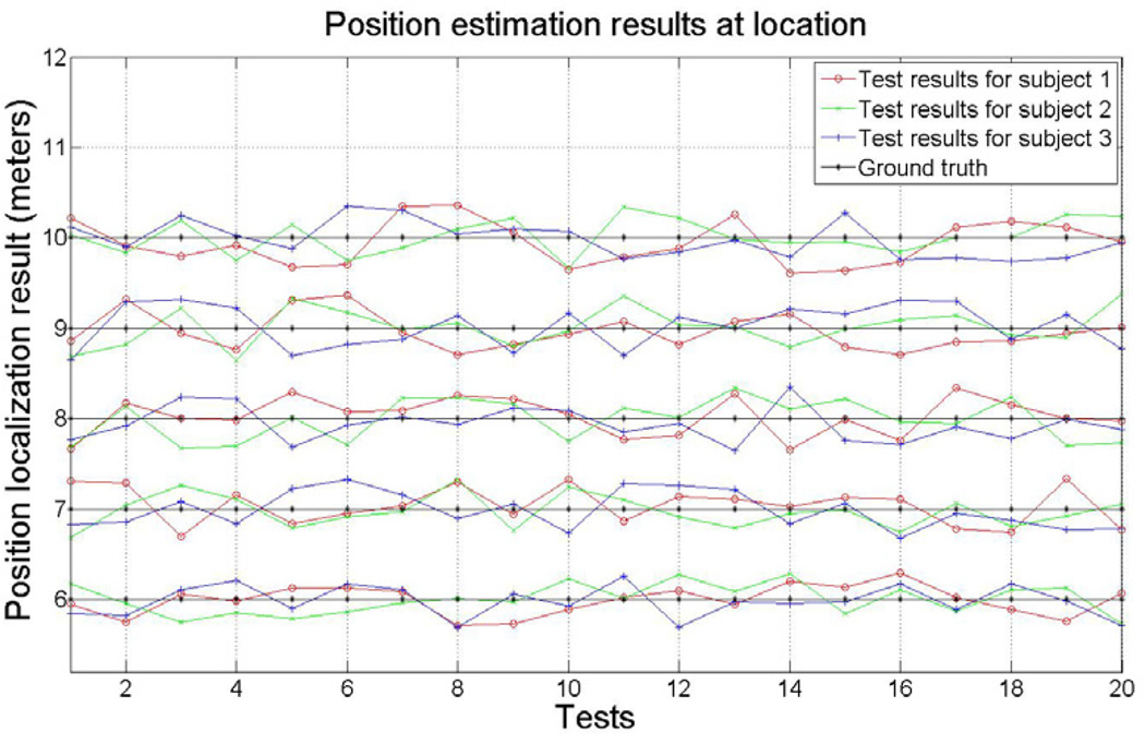
Five points of each hallway were selected as testing locations, which were 10 meters to 6 meters with 1 meter interval from the reference landmark to the subject. Each subject walked in the three hallways twenty times while the images and ground truth were acquired. Results of 6 meters, 8 meters and 10 meters were calculated only from the change of the scales in the matched images according to Eq.(3). Calculation results for positions of 7 meters and 9 meters were obtained based on the moving speed calculation results, as shown in Eq. (6).
Fig. 11 and Table 1 show the comparisons between the position/relative distance estimates by our system and the ground truth values by the measurement platform. It can be seen that our system can precisely localize subjects with the help of pre-established database.
Fig. 11.
Comparison results of location estimation between proposed algorithm and ground truth
IV. Conclusion
We have presented a landmark-based indoor positioning system for blind and visually impaired individuals. A digital camera enabled wearable computer has been designed that unobtrusively acquires both pictorial and motion data as the individual walks. Indoor positioning and localization information is provided to the individual based on matching of the acquired images to those in a pre-established database. Scale changes in images are used to improve estimation accuracy based on a pinhole camera model. Experimental results have shown that this system provides localization information in high accuracy without the need of installing expensive infrastructures. V.
Acknowledgement
This work was supported by the National Institutes of Health Grants No. P30AG024827, U48DP001918, and R01CA165255, and the China National Science Foundation Grant No. 61272351.
Contributor Information
Yicheng Bai, Email: yib2@pitt.edu.
Wenyan Jia, Email: wej6@pitt.edu.
Hong Zhang, Email: dmrzhang@163.com.
Zhi-Hong Mao, Email: zhm4@pitt.edu.
Mingui Sun, Email: drsun@pitt.edu.
References
- 1.Centers for Disease Control and Prevention. What percentage of American's are blind and or deaf. 2008 Available: http://wikianswerscom/Q/What_percentage_of_American's_are_blind_and_or_deaf. [Google Scholar]
- 2.Andreas H, Joachim D, Thomas E. Design and development of an indoor navigation and object identification system for the blind. ACM SIGACCESS Accessibility and Computing. 2003:147–152. [Google Scholar]
- 3.Otsason V, Varshavsky A, LaMarca A, de Lara E. Accurate GSM Indoor Localization. Ubiquitous Computing. 2005;3660:141–158. [Google Scholar]
- 4.Cruz O, Ramos E, Ramirez M. 3D indoor location and navigation system based on Bluetooth; 21st International Conference on Electrical Communications and Computers; 2011. pp. 271–277. [Google Scholar]
- 5.Chumkamon S, Tuvaphanthaphiphat P, Keeratiwintakorn P. A blind navigation system using RFID for indoor environments; 5th International Conference on Electrical Engineering/Electronics, Computer, Telecommunications and Information Technology; 2008. pp. 765–768. [Google Scholar]
- 6.Coughlan J, Manduchi R, Shen H. 1st International Workshop on Mobile Vision. Graz, Austria: 2006. Cell Phone-based Wayfinding for the Visually Impaired. [Google Scholar]
- 7.Bai Y, Li C, Yue Y, Jia W, Li J, Mao Z, Sun M. Designing a wearable computer for lifestyle evaluation; 38th Annual Northeast Bioengineering Conference (NEBEC); 2012. pp. 93–94. [DOI] [PMC free article] [PubMed] [Google Scholar]
- 8.Lowe DG. Object recognition from local scale-invariant features. Proceedings of the Seventh IEEE International Conference on Computer Vision. 1999;2:1150–1157. [Google Scholar]


