Abstract
Implantable drug delivery devices are becoming attractive due to their abilities of targeted and controlled dose release. Currently, two important issues are functional lifetime and non-controlled drug diffusion. In this work, we present a drug delivery device combining an electrolytic pump and a thermo-responsive valve, which are both remotely controlled by an electromagnetic field (40.5 mT and 450 kHz). Our proposed device exhibits a novel operation mechanism for long-term therapeutic treatments using a solid drug in reservoir approach. Our device also prevents undesired drug liquid diffusions. When the electromagnetic field is on, the electrolysis-induced bubble drives the drug liquid towards the Poly (N-Isopropylacrylamide) (PNIPAM) valve that consists of PNIPAM and iron micro-particles. The heat generated by the iron micro-particles causes the PNIPAM to shrink, resulting in an open valve. When the electromagnetic field is turned off, the PNIPAM starts to swell. In the meantime, the bubbles are catalytically recombined into water, reducing the pressure inside the pumping chamber, which leads to the refilling of the fresh liquid from outside the device. A catalytic reformer is included, allowing more liquid refilling during the limited valve's closing time. The amount of body liquid that refills the drug reservoir can further dissolve the solid drug, forming a reproducible drug solution for the next dose. By repeatedly turning on and off the electromagnetic field, the drug dose can be cyclically released, and the exit port of the device is effectively controlled.
I. INTRODUCTION
Drug delivery systems are increasingly important in the field of biomedical research and human therapies. For most therapeutic treatments, the ideal drug concentration profile should be sustained within an effective therapeutic window, which is not easily accomplished by conventional drug delivery approaches1 such as oral ingestions, eye drops, and injections. In contrast to conventional drug delivery systems, implantable drug delivery devices are advantageous in many therapeutic applications due to their unique features of targeted and controlled dose release. Specifically, the devices with versatile and reliable remote controllability are at the frontier of human chronic treatments, for example, for brain tumors.2 Micro-electro-mechanical systems (MEMS) technology offers the potential to develop implantable drug delivery devices with miniaturized size and effective control. Among the preliminary studies, MEMS fabrication-based electrolytic pumps are receiving considerable interest3–6 for delivering a variety of drugs due to their ability of transforming electrical energy directly into mechanical work through swelling, bending, and other deformations. Electrolytic actuation, compared to other actuation mechanisms, usually offers the preponderant advantages of stability, low power consumption, and easy operation.5
Most of the reported works about electrolytic pumps utilized liquid drugs, which suffered from poor long-term application due to drug depletion or the limitation imposed by the maximum diaphragm deformation.6 An alternative approach was investigated by Nazly et al., where the drug was stored in solid-form in the drug reservoir (SDR). A reproducible drug solution was formed by repeatedly dissolving the solid drug into each newly refilled liquid. The constraining factors in Refs. 7 and 8 include the alignment and operation distance between actuation sources. Previously, we combined an SDR method and an electrolysis-driven pump in a simple to operate device for the purpose of long-term applications.9 In this device, the solid drug is dissolved by body liquid entering through the outlet of the device, and the drug liquid is delivered periodically, exhibiting a cyclically pulsed profile. Improving on,9 we added a catalytic reformer to achieve a fast recombination rate of bubbles formed during electrolysis of hydrogen and oxygen. This improvement reduces the time required for a drug delivery pulse from our system, and increases the number of possible delivery cycles within a limited operation time.
Over a long period, undesired drug diffusion from a drug solution to the human liquid environment cannot be ignored at the outlet of the implant. This issue is especially important for therapeutic treatments using more potent drugs: uncontrolled drug diffusion may bring unpredictable harm to patients. Therefore, an effective valve for the drug delivery device is needed. In the previous work, a thermo-responsive poly (N-Isopropylacrylamide) (PNIPAM) valve was developed, which was controlled by inductive heating with an alternating-current-driven electromagnetic field.10 PNIPAM is a thermo-responsive hydrogel, and its volume changes with temperature. By expelling or absorbing water molecules, depending on whether it is above or below a designed lower critical solution temperature (LCST),11,12 respectively, the polymer in the valve channel seals the valve or allows the drug to flow through it.
Besides possible drug diffusion, the reliability of the implants and the biocompatibility of the component materials13 may also be questioned for the in vivo applications due to tissue inflammation,14 foreign body response,15 and biofouling.16,17 For the implantable drug delivery systems, both anti-fouling coating18–22 and biological response modifiers (BRMs) release23–26 can be used to suppress the inflammatory response and the foreign body response.14 For example, the release of dexamethasone loaded poly (lactic-co-glycolic acid) (PLGA) microspheres23 and a variety of nano-porous inorganic coatings27 demonstrate that the implantable drug delivery device's reliability can be improved and its lifetime can be extended as long as the anti-biofouling agent is continuously present around the implant. However, such biology related issues are not addressed in this work. Our system provides a proof of concept of an integration of an electromagnetically powered electrolytic pump with an electromagnetically controlled PNIPAM valve. The main contributions are (1) combination of remotely operated pumping and valve mechanisms, which share the same power source and (2) addition of catalytic reformers in the pumping chamber in order to accelerate the bubble recombination. This addition not only increases the number of delivery cycles but also ensures that more fresh liquid from outside the device can refill the drug reservoir within the valve's closing time. Moreover, the key components of our device involve biocompatible materials, i.e., silicon substrate, Pt/Ti electrodes, and a Pt coated catalytic reformer, whose compatibility is evaluated in Ref. 28. The rest of this paper is organized as follows: Section II presents the prototype, fabrication, and methodology. Experimental results are analyzed in Section III. Conclusions are presented in Section IV.
II. CONCEPT AND FABRICATION
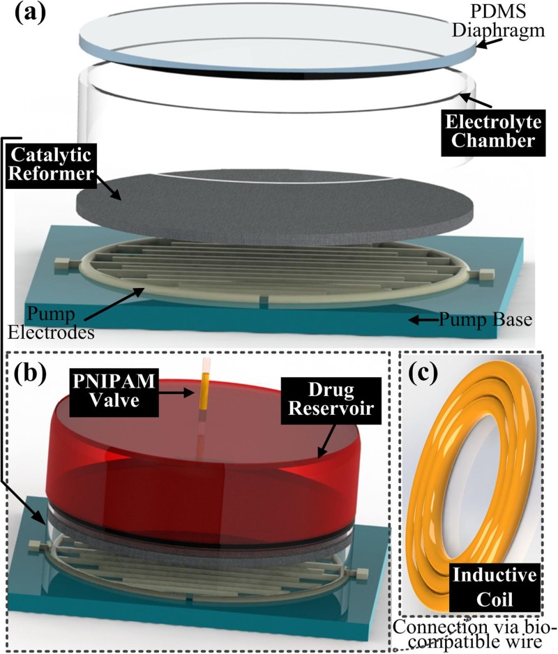
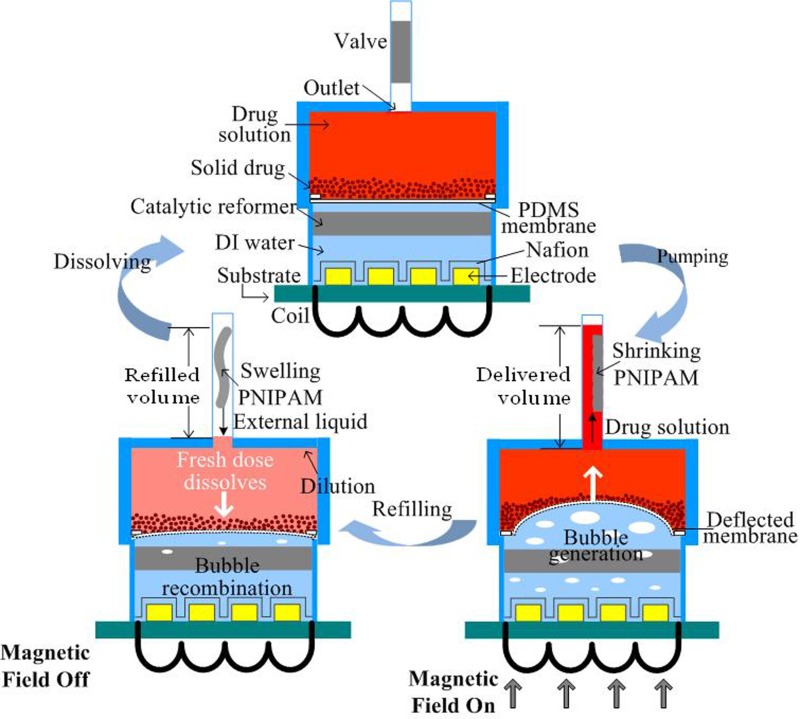
Our proposed device is remotely operated by an AC electromagnetic field that provides the power for the pump and the thermo-responsive valve. The overall design of our proposed device is shown in Fig. 1. The electrolyte chamber (Fig. 1(a)) consists of a catalytic reformer and two interdigitated platinum/titanium (Pt/Ti) electrodes. Both the catalytic reformer and the electrodes are immersed into the electrolyte chamber, and an elastic polydimethylsiloxane (PDMS) membrane separates the pumping chamber from the drug reservoir (Fig. 1(b)) in order to prevent oxidation of the drug solution and unwanted pH changes. The PNIPAM valve controls the exit port of the device. An inductive coil (Fig. 1(c)) connects to the contact pads of the electrodes for powering the pump. Fig. 2 illustrates the device's working principle and major components. In this work, Nafion is uniformly coated onto the electrodes to achieve a higher electrolysis efficiency.5 Pumping the drug fluid and refilling the drug reservoir are based on the deflection of the PDMS membrane.29
FIG. 1.
Exploded view of the device showing its major components.
FIG. 2.
Schematic illustration of the solid drug in reservoir (SDR) based device and its cyclic operation.
When the AC magnetic field is on, the induced voltage in the coil powers the electrode, driving the electrolytic reaction. The electrolysis induced-bubbles (hydrogen and oxygen from the separation of DI water) deform the PDMS membrane, pushing the drug towards the valve. The valve is made of PNIPAM mixed with iron micro-particles. The AC field causes heating of the iron micro-particles via magnetic losses, causing the PNIPAM to shrink when the temperature reaches or passes its LCST (∼41 °C in this work). This change in the PNIPAM opens the valve and allows the drug solution to flow past it. When the magnetic field is off, the PNIPAM swells, sealing the outlet. In the meantime, because of the recombination of electrolysis bubbles into water, the PDMS membrane moves downwards, causing fresh fluid from outside the device to refill the drug reservoir before the valve is fully sealed. This fresh fluid dissolves a certain amount of solid drug, based on the drug's solubility limit, forming the new drug solution for the next dose. The recombination process can be accelerated by a Pt-coated carbon fiber mesh, due to its catalytic properties. In this manner, more fluid can flow back into the drug reservoir to dissolve more of the remaining drug within the valve's closing time. By repeatedly turning on and off the AC field, the drug solution can be delivered cyclically.
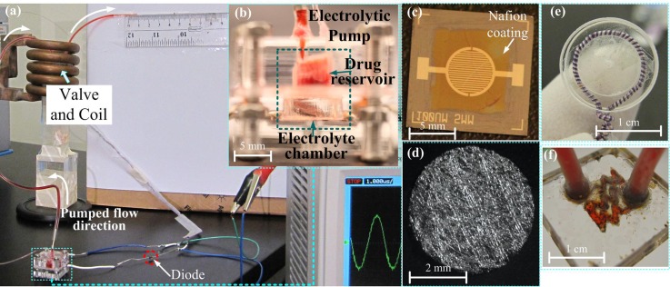
Fig. 3(a) shows the measurement setup with the mounted prototype (Fig. 3(b)); Fig. 3(c) shows the platinum and titanium (Pt/Ti) interdigitated electrodes with Nafion coating; and Fig. 3(d) shows the catalytic reformer. The drug reservoir is made by drilling a cavity into a polymethylmethacrylate (PMMA) substrate; its internal radius is 2.5 mm and its depth is 3 mm. The electrolytic chamber is also made of a PMMA loop with an internal radius of 2.6 mm and a height of 2.7 mm. To ensure that the tests are repeatable, the electrolytic pump is mounted by tightening PMMA holders (2 cm × 2 cm × 2 cm). For prospective drug delivery applications, in order to reduce the size of the entire device, the holder can be substituted by a permanent bonding of the drug reservoir to the actuator chamber.
FIG. 3.
(a) Photographs of the experimental apparatus and the prototypes of the major components; (b) assembled electrolytic pump; (c) image of Nafion coated Pt/Ti electrodes; (d) sputtered platinum coated carbon fiber mesh; (e) inductive coil; and (f) the PNIPAM valve mixed with iron micro-particles.
The Pt/Ti electrodes used in this work were fabricated following a standard lithography process: (i) photoresist deposition and ultraviolet light exposure to define the pattern, (ii) sputter deposition of Ti and then Pt, and (iii) lift-off processing to remove the sacrificial layers. Ti functions as an adhesion layer between Pt and the silicon substrate. The electrodes were 100 μm in width with a gap of 100 μm in between them and their height was 300 nm (with a thickness ratio of Ti/Pt: 1/5). Nafion was spin-coated on the surface of the electrodes, forming a thin film of 320 nm. For fabricating the catalytic reformer, we used carbon fiber paper (from FuelCellStore) with a diameter of 5 mm and thickness of 0.3 mm as a scaffold because it is inert in the electrolyte. Pt was sputter-deposited onto the scaffold. Owing to the porous mesh structure of carbon fiber paper, the contact area between the Pt and the electrolysis bubble is large, increasing the catalytic efficiency. A Litz wire coil (AWG 46) with a diameter of 10 mm and 1 turn (Fig. 3(e)) was connected to the contact pads of the electrodes. The voltage induced by the AC field was then rectified by a diode for powering the pump, and an oscilloscope (Agilent DS01012A) was used to measure the voltage induced in the coil. The electromagentic field was generated by an induction heating system (operated at 450 kHz, purchased from IEW GmbH).
The PNIPAM valve (Fig. 3(f)) was constructed using a serpentine-shaped PMMA micro-channel, which was filled with a mixture of PNIPAM and iron micro-particles (<10 μm, Sigma-Aldrich Co. LLC). The heat for opening the valve is generated by magnetic losses in the iron particles induced by the electromagnetic field. We found that the size of the iron particles we used did not negatively affect the valve's function, yet they are considerably more cost efficient than nano-sized beads like the ones used previously.10 The serpentine micro-channel (width: 0.4 mm and depth: 0.3 mm) was made on a PMMA substrate using a laser cutter (Universal PLS6.75). This serpentine structure helps keeping the PNIPAM in place, and has an increased area efficiency compared to a straight channel.10 After uniformly distributing 3 mg of the iron micro-particles into the micro-channel, the PMMA substrate was bonded to another PMMA substrate using a thermal-compression bonding system (INSTRON Dual Column Testing Systems). The PNIPAM hydrogel was formed by mixing equal volumes of two different solutions.30 The first solution included 20 wt. % of N-Isopropylacrylamide (NIPAAM), 4 wt. % of N, N, N, N-dimethylene bis (acrylamide) (BIS) as a crosslinker, and 2% v/v TEMED (N, N, N′, N′-tetramethylethylenediamine) as a reaction accelerator. The second solution was 4.5 wt. % of potassium persulfate (KPS) used as an initiator of the reaction. We injected these two fluids into the valve channel through a Y-shape junction with an equal injection rate; the polymerization of the PNIPAM hydrogel occured shortly after the two solutions diffused together.
III. EXPERIMENTS AND DISCUSSION
A. Electrolytic pump
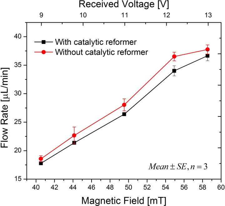
In order to focus on the features of the catalytic reformer, the PNIPAM valve was not included in the experiments described in this section. The magnetic field applied can be calculated using Faraday's law, in which the area of the coil, number of turns, and the field frequency determine the voltage induced in a coil. A red dye was used as a drug solution substitute, which could easily be tracked. A digital camera was placed in front of the test setup to record the displacement of the dye across a glass capillary at the outlet of the device. The displacement was measured using a ruler, as depicted in Fig. 3. Dividing the forward displacement of the dye by the time required for the displacement yielded the flow rate. Fig. 4 shows that the flow rate can be controlled by the electro-magnetic field amplitude. For each of the measurement points, a field was applied for 20 s, and then the field was turned off until all bubbles were recombined before the next measurement was started. Increasing the amplitude from 40.5 mT to 58.5 mT resulted in a more than doubling of the flow rate from 17 μl/min to 37 μl/min. Moreover, the pump with one catalytic reformer element has a slightly reduced flow rate, which was caused by an accelerated recombination of bubbles into water even during the stage of electrolysis-bubble generation.
FIG. 4.
Magnetic field controlled flow rates (mean ± standard error, n = 3) of the electrolytic pump with one catalytic reformer element and without a catalytic reformer under the same conditions.
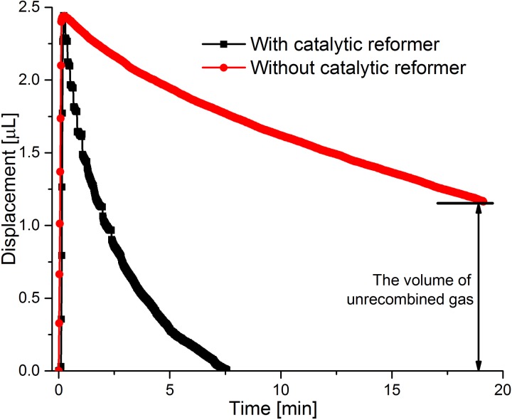
In order to further clarify the function of the catalytic reformer, the dye displacement profiles under a 40.5 mT electro-magnetic field in the “On/Off” mode were obtained for two pump versions, one with a catalytic reformer element and one without it. As shown in Fig. 5, the electromagnetic field was switched on until the PDMS membrane reached a deflection of 2.5 μl. Although the actuation time for the pump with and without the catalytic reformer is only slightly different, the pump without the reformer takes a considerably longer time to recombine the bubbles. Specifically, with a catalytic reformer, the displacement returns to zero after 7.5 min, and it is still at 1.2 μl after 18 min without a catalytic reformer. Recombining all the generated bubbles, in the case of the pump without a catalytic reformer takes more than 1 h, as also found in Ref. 6. Therefore, the pump with catalytic reformer is much more suitable for the SDR approach because of its fast recombination rate, allowing fresh fluid to rapidly refill the drug reservoir before the valve seals the outlet.
FIG. 5.
Dye displacement of electrolytic pump with one catalytic reformer element and without a catalytic reformer under the same conditions. An electromagnetic field of 40.5 mT is applied.
B. Electrolytic pump and PNIPAM valve
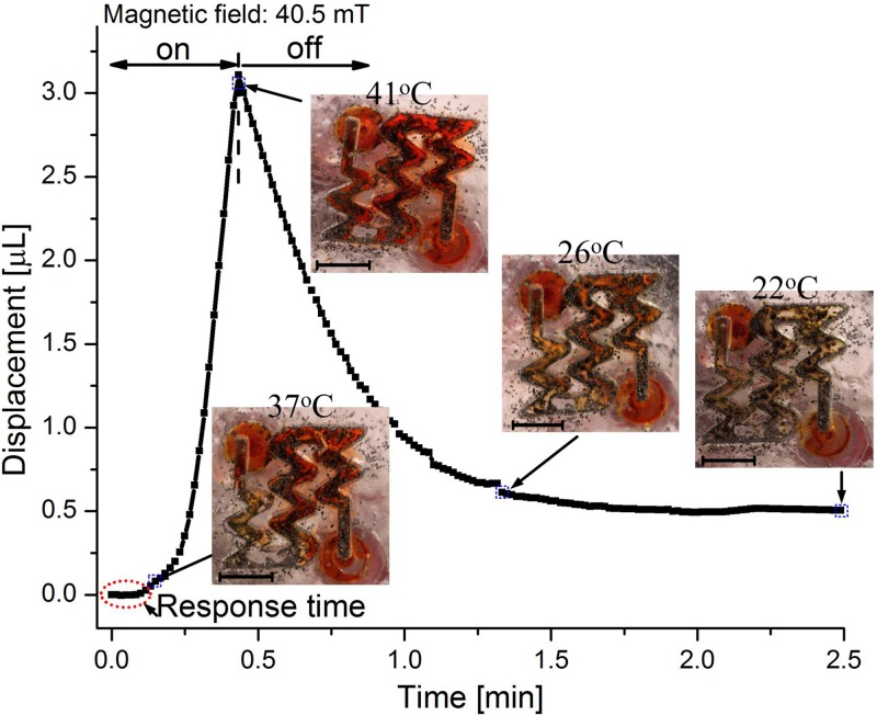
In this subsection, an integrated system combining the PNIPAM valve and the electrolytic pump was investigated. The setup, as shown in Fig. 3, was utilized for measuring the dye displacement over the valve. In order to further improve the recombination rate, we added three catalytic reformer elements to the system. The temperature of the PNIPAM valve was monitored by an infrared thermometer gun (Thermo Fisher Scientific, Inc.). The dye displacement together with the valve's temperature under an electromagnetic field of 40.5 mT is shown in Fig. 6. The PNIPAM valve required several seconds of response time before it opened. Following the response time, a small volume of liquid was displaced, while the temperature of the valve was approximately 37 °C. During this time, the valve was not completely open; however, a small percentage of the valve had reacted to the temperature change. At this point, little liquid can pass through the valve during the PDMS membrane deflection. Afterwards, the slope of the displacement (or flow rate) increased, indicating that the valve was gradually opening. At a displacement of approximately 1 μl (∼20 s), the slope of the displacement curve becomes linear (or constant flow rate), implying that the PNIPAM hydrogel has completely shrunken and the valve has reached its open state. The electromagnetic field was applied until the volume displacement reached 3 μl (41 °C at this point).
FIG. 6.
Pumping profile under an electromagnetic field of 40.5 mT when the thermo-responsive valve was used in combination with a pump with three catalytic reformer elements. The insets illustrate the states of the valve at different time points and the corresponding temperatures. Black particles are the iron micro-particles. Scale bars are 3 mm.
After turning off the electromagnetic field, recombination in the electrolytic chamber occurred, retracting the PDMS membrane and drawing liquid back towards the drug reservoir. By using three catalytic reformer elements, the recombination rate became much faster (compare Fig. 6 with Fig. 5). During the bubble recombination, the PNIPAM cooled down and swelled, so that the valve closed. The valve was nearly closed after about 1 min (when it reached 26 °C). When the temperature of the valve dropped to 22 °C, the valve was fully closed, leaving a displacement of 0.5 μl. This remaining displacement was caused because the valve's closing time was shorter than the pump's recombination time under the chosen parameters. This result demonstrates the valve's ability to properly seal the outlet.
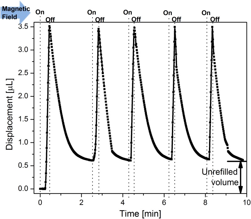
In order to demonstrate the feasibility and stability of the SDR approach for multiple drug delivery doses, we operated the device in the “on/off” mode several times. In each cycle, the electromagnetic field was turned on until the dye displacement reached a value of 3.5 μl. After switching off the field, the dye flowed back and the PNIPAM hydrogel expanded. When the reverse dye flow stopped, we turned the electromagnetic field on again for another cycle. Fig. 7 shows the result of this cyclic operation. It can be observed that by pumping up to 3.5 μl in the first cycle, an un-refilled volume of around 0.5 μl remained. This un-refilled volume is due to the bubble recombination being slower than the valve's closing time, and becomes a stable offset after the first cycle. During the following cycles, only 3 μl were pumped and the displacement reached its original value at the end of the refilling period. This observation suggests that a maximum volume of approximately 3 μl can be refilled within the valve's closing time and the same amount can be repeatedly pumped without any loss of volume over time. This condition must be satisfied for long-term operation of a system that continuously replenishes drug supply by dissolving an internal solid drug that continuously saturates the fluid. The recombination rate (or the slope of the negative displacement) at each pulse is slightly different, because the catalytic reforming elements were not mechanically fixed within the chamber and they would randomly move upon the bubble generation, thereby, changing the contact area between the catalyst and bubble. In future work, the catalytic reformer should be permanently bonded to the electrolyte chamber, in order to achieve a more stable bubble recombination rate.
FIG. 7.
Cyclic liquid displacement of the dye when a device with a pump, three catalytic reformer elements, and a PNIPAM valve is operated with an electromagnetic field of 40.5 mT that is periodically turned on and off.
IV. CONCLUSION
In this work, we have demonstrated an electromagnetically controlled drug delivery device with an electrolysis-actuated pump and a thermo-responsive valve. Both the pumping mechanism and the valve are operated remotely by the same electromagnetic field. The device is capable of releasing a single dose or cyclic doses of drug from a solid drug reservoir, and it features a valve-controlled exit port that prevents undesired diffusion. The operation mechanism of the device includes two stages, corresponding to the electromagnetic field being “on” or “off.” In the “on” state, the generated electrolysis-bubbles drive drug delivery through the open valve. In the “off” state, the bubble recombination draws fresh liquid into the drug reservoir, which is needed for dissolving a new drug dose, and the PNIPAM valve closes, sealing the exit port. A cyclic operation of the device shows repeatable and stable behavior.
Moreover, the bubble generation rate and the recombination rate of the pump can be adjusted by selecting different sizes for the inductive coil and a different number of catalytic reformers. For example, a reduced size of the coil can lead to a lower flow rate. The function of the valve is to avoid any drug diffusion, but it also requires that the recombination rate should be accelerated as much as possible to refill the drug reservoir before the valve fully closes. The required recombination rate was achieved by using three catalytic reformer elements inside of the electrolytic chamber. The device provides a suitable platform for the SDR approach, which is intended for a remotely operated drug delivery system for long-term therapeutic treatments.
References
- 1. Meng E. and Hoang T., “ MEMS-enabled implantable drug infusion pumps for laboratory animal research, preclinical, and clinical applications,” Adv. Drug Delivery Rev. 64(14), 1628–1638 (2012). 10.1016/j.addr.2012.08.006 [DOI] [PMC free article] [PubMed] [Google Scholar]
- 2. Li Y., Duc H. L. H., Tyler B., Williams T., Tupper M., Langer R., and Cima M. J., “ In vivo delivery of BCNU from a MEMS device to a tumor model,” J. Controlled Release 106(1), 138–145 (2005). 10.1016/j.jconrel.2005.04.009 [DOI] [PubMed] [Google Scholar]
- 3. Li P.-Y., Shih J., Lo R., Saati S., Agrawal R., Humayun M. S., Tai Y.-C., and Meng E., “ An electrochemical intraocular drug delivery device,” Sens. Actuators, A 143(1), 41–48 (2008). 10.1016/j.sna.2007.06.034 [DOI] [Google Scholar]
- 4. Li P.-Y., Sheybani R., Gutierrez C. A., Kuo J. T. W., and Meng E., “ A parylene bellows electrochemical actuator,” J. Microelectromech. Syst. 19(1), 215–228 (2010). 10.1109/JMEMS.2009.2032670 [DOI] [PMC free article] [PubMed] [Google Scholar]
- 5. Roya S. and Meng E., “ High-efficiency MEMS electrochemical actuators and electrochemical impedance spectroscopy characterization,” J. Microelectromech. Syst. 21(5), 1197–1208 (2012). 10.1109/JMEMS.2012.2203103 [DOI] [Google Scholar]
- 6. Heidi G., Sheybani R., Li P. Y., Lo Mann R., and Meng E., “ An implantable MEMS micropump system for drug delivery in small animals,” Biomed. Microdevices 14(3), 483–496 (2012). 10.1007/s10544-011-9625-4 [DOI] [PMC free article] [PubMed] [Google Scholar]
- 7. Nazly P. F., Jackson J. K., Burt H. M., and Chiao M., “ A magnetically controlled MEMS device for drug delivery: Design, fabrication, and testing,” Lab Chip 11(18), 3072–3080 (2011). 10.1039/c1lc20438f [DOI] [PubMed] [Google Scholar]
- 8. Nazly P. F., Jackson J. K., Burt H. M., and Chiao M., “ On-demand controlled release of docetaxel from a battery-less MEMS drug delivery device,” Lab Chip 11(16), 2744–2752 (2011). 10.1039/c1lc20134d [DOI] [PubMed] [Google Scholar]
- 9. Yi Y., Buttner U., and Foulds I. G., “ Towards an implantable pulsed mode electrolytic drug delivery system,” in 17th International Conference on Miniaturized Systems for Chemistry and Life Sciences (MicroTas) (Germany, 2013), pp. 527–529. [Google Scholar]
- 10. Ghosh S. et al. , “ Oscillating magnetic field-actuated microvalves for micro- and nanofluidics,” J. Phys. D: Appl. Phys. 42(3), 135501 (2009). 10.1088/0022-3727/42/13/135501 [DOI] [Google Scholar]
- 11. Hirokawa Y. and Tanaka T., “ Volume phase transition in a nonionic gel,” J. Chem. Phys. 81(12), 6379–6380 (1984). 10.1063/1.447548 [DOI] [Google Scholar]
- 12. Saunders R. and Vincent B., “ Microgel particles as model colloids: theory, properties and applications,” Adv. Colloid Interface Science 80(1), 1–25 (1999). 10.1016/S0001-8686(98)00071-2 [DOI] [Google Scholar]
- 13. Zhuolin X., Wang H., Pant A., Pastorin G., and Lee C., “ Development of vertical SU-8 microtubes integrated with dissolvable tips for transdermal drug delivery,” Biomicrofluidics 7(2), 026502 (2013). 10.1063/1.4798471 [DOI] [PMC free article] [PubMed] [Google Scholar]
- 14. Santhisagar V., Tomazos I., Burgess D. J., Jain F. C., and Papadimitrakopoulos F., “ Emerging synergy between nanotechnology and implantable biosensors: A review,” Biosens. Bioelectron. 25(7), 1553–1565 (2010). 10.1016/j.bios.2009.12.001 [DOI] [PMC free article] [PubMed] [Google Scholar]
- 15. Natalie W., Moussy F., and Reichert W. M., “ Characterization of implantable biosensor membrane biofouling,” Fresenius' J. Anal. Chem. 366(6–7), 611–621 (2000). 10.1007/s002160051556 [DOI] [PubMed] [Google Scholar]
- 16. Raeann G., Kehoe J. J., Barnes S. L., Kornilayev B. A., Alterman M. A., and Wilson G. S., “ Protein interactions with subcutaneously implanted biosensors,” Biomaterials 27(12), 2587–2598 (2006). 10.1016/j.biomaterials.2005.11.033 [DOI] [PubMed] [Google Scholar]
- 17. Wisniewski N., Klitzman B., Miller B., and Reichert W. M., “ Decreased analyte transport through implanted membranes: Differentiation of biofouling from tissue effects,” J. Biomed. Mater. Res. 57(4), 513–521 (2001). [DOI] [PubMed] [Google Scholar]
- 18. Yoshinori O., Bhardwaj U., Papadimitrakopoulos F., and Burgess D. J., “ A review of the biocompatibility of implantable devices: current challenges to overcome foreign body response,” J. Diabetes Sci. Technol. 2(6), 1003–1015 (2008). 10.1177/193229680800200610 [DOI] [PMC free article] [PubMed] [Google Scholar]
- 19. Upkar B., Papadimitrakopoulos F., and Burgess D. J., “ A review of the development of a vehicle for localized and controlled drug delivery for implantable biosensors,” J. Diabetes Sci. Technol. 2(6), 1016–1029 (2008). 10.1177/193229680800200611 [DOI] [PMC free article] [PubMed] [Google Scholar]
- 20. Prashanth A., Karajanagi S. S., Kane Ravi S., and Dordick J. S., “ Polymer–nanotube–enzyme composites as active antifouling films,” Small 3(1), 50–53 (2007). 10.1002/smll.200600312 [DOI] [PubMed] [Google Scholar]
- 21. Kaushal R., Raravikar N. R., Kim D. Y., Schadler L. S., Ajayan P. M., and Dordick J. S., “ Enzyme-polymer-single walled carbon nanotube composites as biocatalytic films,” Nano Lett. 3(6), 829–832 (2003). 10.1021/nl034131k [DOI] [Google Scholar]
- 22. Luckarift H. R., Dickerson M. B., Sandhage K. H., and Spain J. C., “ Rapid, room-temperature synthesis of antibacterial bionanocomposites of lysozyme with amorphous silica or titania,” Small 2(5), 640–643 (2006). 10.1002/smll.200500376 [DOI] [PubMed] [Google Scholar]
- 23. Upkar B., Sura R., Papadimitrakopoulos F., and Burgess D. J., “ Controlling acute inflammation with fast releasing dexamethasone-PLGA microsphere/PVA hydrogel composites for implantable devices,” J. Diabetes Sci. Technol. 1(1), 8–17 (2007). 10.1177/193229680700100103 [DOI] [PMC free article] [PubMed] [Google Scholar]
- 24. Norton L. W., Koschwanez H. E., Wisniewski N. A., Klitzman B., and Reichert W. M., “ Vascular endothelial growth factor and dexamethasone release from nonfouling sensor coatings affect the foreign body response,” J. Biomed. Mater. Res., Part A 81(4), 858–869 (2007). 10.1002/jbm.a.31088 [DOI] [PMC free article] [PubMed] [Google Scholar]
- 25. Patil S. D., Papadmitrakopoulos F., and Burgess D. J., “ Concurrent delivery of dexamethasone and VEGF for localized inflammation control and angiogenesis,” J. Controlled Release 117(1), 68–79 (2007). 10.1016/j.jconrel.2006.10.013 [DOI] [PubMed] [Google Scholar]
- 26. Frost M. C., Rudich S. M., Zhang H., Maraschio M. A., and Meyerhoff M. E., “ In vivo biocompatibility and analytical performance of intravascular amperometric oxygen sensors prepared with improved nitric oxide-releasing silicone rubber coating,” Anal. Chem. 74(23), 5942–5947 (2002). 10.1021/ac025944g [DOI] [PubMed] [Google Scholar]
- 27. Evin G., Nagesha D., Sridhar S., and Amiji M., “ Nanoporous inorganic membranes or coatings for sustained drug delivery in implantable devices,” Adv. Drug Delivery Rev. 62(3), 305–315 (2010). 10.1016/j.addr.2009.11.003 [DOI] [PubMed] [Google Scholar]
- 28. Gabriela V., Shive M. S., Shawgo R. S., Recum H. V., and Anderson J. M., Michael J. Cima, and Robert Langer, “Biocompatibility and biofouling of MEMS drug delivery devices,” Biomaterials 24(11), 1959–1967 (2003). 10.1016/S0142-9612(02)00565-3 [DOI] [PubMed] [Google Scholar]
- 29. Yi Y., Buttner U., and Foulds I. G., “ A cyclically actuated electrolytic drug delivery device,” Lab Chip (published online 2015). 10.1039/c5lc00703h [DOI] [PubMed] [Google Scholar]
- 30. Kim J. W., Utada A. S., Fernández-Nieves A. et al. , “ Fabrication of monodisperse gel shells and functional microgels in microfluidic devices,” Angew. Chem. 119(11), 1851–1854 (2007). 10.1002/ange.200604206 [DOI] [PubMed] [Google Scholar]


