

Abstract
Implementations of Lab-on-a-Chip technologies for in-situ analysis of small model organisms and embryos (both invertebrate and vertebrate) are attracting an increasing interest. A significant hurdle to widespread applications of microfluidic and millifluidic devices for in-situ analysis of small model organisms is the access to expensive clean room facilities and complex microfabrication technologies. Furthermore, these resources require significant investments and engineering know-how. For example, poly(dimethylsiloxane) soft lithography is still largely unattainable to the gross majority of biomedical laboratories willing to pursue development of chip-based platforms. They often turn instead to readily available but inferior classical solutions. We refer to this phenomenon as workshop-to-bench gap of bioengineering science. To tackle the above issues, we examined the capabilities of commercially available Multi-Jet Modelling (MJM) and Stereolithography (SLA) systems for low volume fabrication of optical-grade millifluidic devices designed for culture and biotests performed on millimetre-sized specimens such as zebrafish embryos. The selected 3D printing technologies spanned a range from affordable personal desktop systems to high-end professional printers. The main motivation of our work was to pave the way for off-the-shelf and user-friendly 3D printing methods in order to rapidly and inexpensively build optical-grade millifluidic devices for customized studies on small model organisms. Compared with other rapid prototyping technologies such as soft lithography and infrared laser micromachining in poly(methyl methacrylate), we demonstrate that selected SLA technologies can achieve user-friendly and rapid production of prototypes, superior feature reproduction quality, and comparable levels of optical transparency. A caution need to be, however, exercised as majority of tested SLA and MJM resins were found toxic and caused significant developmental abnormalities in zebrafish embryos. Taken together, our data demonstrate that SLA technologies can be used for rapid and accurate production of devices for biomedical research. However, polymer biotoxicity needs to be carefully evaluated.
INTRODUCTION
Growing medical challenges continuously spur demands for low cost and miniaturized bioanalytical systems in drug discovery pipelines and biomedical research.1,2 Microfluidic Lab-on-a-Chip (LOC) technologies are particularly appealing for this purpose and experienced a significant growth thanks to advances in physics, electronics, and material sciences.3 They have the potential to deliver meaningful technological advances in modern biomedicine, through the ability to provide appropriate low-cost micro-environments for screening cells, tissues, and even small model organisms.4–6 The implementations of LOC technologies for in-situ analysis of small model organisms and embryos (both invertebrate and vertebrate) are particularly attracting a mounting interest in biomedical community.5,7 This is because there is still lack of technologies for attaining high-throughput and high quality phenotypic data from small model organisms at the earliest opportunity during the basic or translational research process.5,7 The major hurdle to wide-spread deployment of high-throughput phenotypical screens on small model organisms is the lack of fully automated, integrated, and high-throughput analytical platforms.5,7–9 For instance, visualizing zebrafish embryo development and internal organs requires manipulating and properly orienting the animals, which is currently performed by manually transferring embryos from the reservoirs to microwells and manually orienting them. These manual processes are slow, tedious, and unreliable for high-throughput phenotypical screening.5,8,9
Yet, despite the growing interest and needs of the biomedical community, the developments in millifluidic devices for small model organisms are rather limited compared to other burgeoning fields of LOC.5 The reason behind this can be explained by the fact that prototyping and fabrication of millimetre scale devices that can accommodate large organisms are difficult and time consuming using the standard lithography techniques due to the inherent processing time required to obtain pattern definition of the photoresist structures.9 Current microfabrication methods utilizing biocompatible polymers are also largely restricted to two dimensional (2D) or two and a half dimensional (2.5D) structures while not permitting fabrication of monolithic three dimensional (3D) devices with complex geometries.10,11 Advances in Lab-on-a-Chip manufacturing over last decade have allowed for inexpensive prototyping of a plethora of chip-based devices for biomedical studies mostly in biocompatible and optically transparent elastomeric polymers such as poly(dimethylsiloxane) (PDMS) and thermoplastics such as poly(methyl methacrylate) (PMMA).12,13 PDMS and plastic molding techniques are, however, inherently 2D layer-by-layer techniques requiring manual bonding and assembly that introduces operator-related reproducibility issues, while polymer flexibility has been postulated to impede a transition from prototype phase to a scaled up production.10 Fabrication of devices using those relatively inexpensive polymers still requires clean room facilities and advanced know-how. Therefore, the most pressing hurdle to development of innovative devices for the biomedical community is the constant need to access expensive and complex microfabrication technologies that require significant know-how and resources.4,10,14,15 The latter are unattainable to gross majority of biomedical laboratories willing to pursue development of bespoke chip-based platforms for small-scale studies on small model organisms. Furthermore, most bio-medical researchers are inexperienced in microfabrication and therefore find all current microfluidic fabrication processes challenging. This forces them instead of adopting LOC technologies to turn to inferior but readily available conventional solutions.10,14 We refer to this phenomenon as workshop-to-bench gap of bioengineering science, in analogy to the well-recognized bench-to-bed gap in biomedical sciences.4
Therefore, we postulate that to close the existing gap between the rapid growth of Lab-on-the-Chip designs and the stagnancy in their application by biomedical and pharmaceutical research community, we need to develop streamlined and affordable prototyping/manufacturing methods.14,16 The latter need to utilize advanced, biocompatible materials with straightforward manufacturing methods to enable accelerated design, validation, and optimization of LOC technologies at the end-user level.4 In this regard, additive manufacturing technologies seem particularly appealing. Recent revolution in commercial and personal 3D printing and wide access to 3D Computer Assited Design (CAD) software has already spurred an explosion of inventions from electronics to mechanical engineering.17,18 Furthermore, recent developments in advanced additive manufacturing technologies capable of reproducing feature sizes of approximately 100 μm have opened up avenues for novel fabrication techniques in bioengineering.10,15,16 The range of applications of 3D printing in biomedical engineering include biomodels for diagnosis, surgical training, hard and soft tissue replacement, biodevices, and tissue engineering.19,20 In particular, biodevices for tissue engineering have been widely reported using a wide range of additive processes and materials.21,22
Despite the rapidly growing usage of additive manufacturing in bioengineering and tissue engineering, surprisingly few studies have been performed to examine their suitability of optically transparent 3D printed microfluidic systems for live cell culture, and no reports so far investigated biological implications of in situ culture of embryos and small model organisms in 3D printed materials. This has been due to two major factors: lack of sufficient resolution of current rapid-prototyping methods and limited optical transparency of polymers to allow imaging of living specimens. The biocompatibility of materials used in 3D printing is largely unknown. Similarly, the chemical resistance/reactivity of currently available 3D printed polymers is poorly characterized.11 Photocurable resins commonly used in additive manufacturing such as acrylates and epoxy resins are not designed for applications in aqueous environments and could be toxic to biological specimens.11 Moreover, epoxy-based resins have been reported to expand heavily in contact with aqueous samples.11 For example, Somos WaterShed XC resin series of photocurable polymers is one of the few commercially available resins that allow printing of low water absorbing structures.10,11
Microfluidic application of additive manufacturing has been initially shown by McCullough and Yadavalli23 by surface modification of 3D printed, fused deposition modeling (FDM) devices using poly(acrylonitrile butadiene styrene) (ABS). This allowed for the creation of a non-biofouling surface LOC device suitable for chemical reactions; however, optical transparency was not possible due to the use of ABS. A similar approach by Kitson et al.24 demonstrated that chemical reactionware for millifluidic and microfluidic LOC devices can be fabricated using basic FDM based printing. However, neither of these methods allow for high-resolution fabrication (<100 μm) of transparent parts suitable for optical or high-definition epifluorescence imaging. Yuen25 was one of the first to describe a plug-n-play and modular microfluidic system fabricated using stereolithograpy (SLA) process. Those prototypes were, however, not fabricated in optical grade polymers and were not assessed for their biological compatibility, quantitative 3D topographic surface mapping, and potential autofluorescence.25 Recently, there has been a resurgence of interest in using commercially available stereolithography for medium volume production and rapid prototyping of optically transparent microfluidic devices.14,16 SLA is an established additive fabrication technique that uses a liquid photopolymer resin. The resin is cured by a focused laser beam or light-emitting diode (LED) light source that illuminates the polymer point-to-point in three dimensions in a vector raster approach.10,14 Advances and raising popularity of industrial applications of SLA printers have led to development of systems with laser beam diameters between 50 and 100 μm and z-layer capabilities of 25–50 μm.10,14 Such resolution combined with capabilities to use optically transparent resins provides us with new user-friendly fabrication of both micro- and millifluidic biodevices.14 Importantly, SLA technique is not restricted by the geometrical constrains of pseudo-3D soft lithography and can produce monolithic and complex 3D microfluidic geometries directly.14,16 The main limitation of SLA is the necessity to drain and clear out the uncured liquid resin from the microchannels. This process can create post-processing challenges as reported recently by others.10,16 However, there are several recent examples of successful SLA produced devices. Most notably, as reported by Bhargava et al., SLA has been successfully used to fabricate a modular microfluidic system composed of interconnected, discrete 3D printed cubes. The basic modular elements featured an array of elaborate internal plumbing to perform specific passive functions.26 Rogers et al.15 reported recently on 3D printed microfluidic devices with integrated membrane-based valves, where fabrication was performed with a low-cost commercially available stereolithographic 3D printer. Both Au et al.10 and Shallan et al.14 described cost-effective use of either mail-to order SLA services or an inexpensive commercially available stereolithographic printers to fabricate robust microfluidic devices with flow channel cross sectional dimensions >500 μm. The studies listed above did not, however, provide a comprehensive side-by-side evaluation of different 3D printing technologies for making biocompatible millifluidic devices in terms of resolution, materials, surface topology, optical clarity, and polymer autofluorescence. Moreover, they left largely unexplored any potential biocompatibility issues of currently available 3D printed polymers.
In this work, we capitalized on recent developments in high-definition additive manufacturing systems and investigated both Multi-Jet Modelling (MJM) and SLA for their applications in rapid prototyping and low volume fabrication of optical-grade millifluidic devices with complex fluidic geometries and high-aspect ratios. Four separate additive manufacturing technologies were selected (three SLA and one MJM system) based on a capability to print optically transparent polymers with z-resolutions of at least 50 μm as described in Sec. II. The selected technologies spanned a range from affordable personal desktop systems to high-end professional printers. In our study, we addressed resolution, materials, surface topology, optical clarity, autofluorescence, and also critical biocompatibility concerns that have not been so far systematically studied. The main motivation of our work was to pave the way for off-the-shelf and user-friendly 3D printing methods in order to rapidly and inexpensively build optically transparent millifluidic devices with complex geometric features and to reduce the need to use clean room environment and conventional microfabrication techniques.
MATERIALS AND METHODS
3D CAD design
Prototypes were designed and modeled using SolidWorks 2011 (Dassault Systems SolidWorks Corp, USA) CAD package. Completed STL files were verified using SolidEdge (Siemens PLM Software, United Kingdom). Millifluidic channel geometries were created as filleted tubular channels accommodating the spherical nature of zebrafish embryos. Nozzles were included in the design to enable rapid fluidic connectivity. This eliminated any need for post-printing chip modifications. Completed STL files were then processed by 3D printers' software packages.
Soft lithography
Replica molding was performed in PDMS (Sylgard 184; DowCorning Corp, Midland, MI, USA) according to a standard protocol.13,27 Briefly, the PDMS was mixed at a 10:1 (w/w) ratio of elastomer base to curing agent and degassed at 40 Torr to remove any residual air bubbles. PDMS was then poured on a PMMA master to achieve approximately 5 mm thickness and cured thermally at 80 °C for up to 1 h.
Laser micromilling
A non-contact, 30 W CO2 laser cutting system equipped with a High Power Density Focusing Optics (HPDFO)™ and providing a 50 μm laser beam spot (Universal Laser Systems, USA) was utilized to ablate structures photo-thermally in PMMA as described earlier. The laser cutting system achieved x-y accuracy of up to 3 μm.
MJM fabrication
HD3500 Plus (3D Systems, USA) high definition 3D printer was characterized by 25 μm x-y resolution and 16 μm layer thickness deposition. VisiJet Crystal resin (3D Systems) with VisiJet S300 Support Wax (3D Systems) was used as per the manufacturer's standard operating protocol. The post-processing of prototypes required several subsequent steps to remove VisiJet S300 Support Wax such as (i) oven treatment at 70 °C for 30 min; (ii) ultrasonic cleaning in canola oil at 55 °C for 10 min; (iii) ultrasonic cleaning in canola oil at 55 °C combined with flushing devices with warm canola oil (55 °C) at a flow rate at 70 ml/min oil for up to 5 min; (iv) washing with Decon 90 detergent for 5 min to flush out oil and remaining wax. Moreover, to achieve acceptable levels of optical transparency, VisiJet Crystal resin required also mechanical polishing using 10.3 μm grit pad followed by 9 μm diamond paste polishing (Mold Makers 9-STD GREEN; Boride Engineered Abrasives, USA), with a high-quality modeling heads (Dremel, USA).
SLA fabrication
Selected systems were used such as (i) Viper Pro (3D Systems) using Watershed 11122XC (DSM Somos, USA) or Dreve Fototec 7150 Clear (Dreve Otoplastik) resins. The Viper Pro was characterized by 25 μm x-y resolution and 50 μm layer thickness deposition; (ii) ProJet 7000HD using VisiJet SL Clear resin (3D Systems). The system was characterized by 25 μm x-y resolution and 50 μm layer thickness deposition; and (iii) Form 1 using Clear resin (FormLabs, USA). The system was characterized by 300 μm x-y resolution and 50 μm layer thickness deposition. All chip prototypes were printed according to the manufacturers' operating manuals using the appropriate software unless otherwise stated. Form 1-printed prototypes were exposed to an UV light (Emission 350 nm) in a standard tissue hood for 12 h to harden the polymer. Post-processing of all SLA prototypes included three independent flushes 99% isopropyl alcohol to remove any non-polymerised resin residues. To achieve acceptable levels of optical transparency, Dreve Fototec 7150 Clear and Form Clear resins required also mechanical polishing using 10.3 μm grit pad followed by 9 μm diamond paste polishing (Mold Makers 9-STD GREEN; Boride Engineered Abrasives, USA), with a high-quality modeling heads (Dremel, USA).
Zebrafish embryo culture and imaging
Adult transgenic zebrafish (Fli1a:EGFP) were held in a recirculating aquatic system on a 14 h:10 h light:dark cycle. Fish were fed twice daily, once with live crustacean Artemia sp. and once with dry food. Environmental temperature was maintained at 27.5 °C and environmental pH at 7.5–8.0. Zebrafish embryos were obtained from pair-wise mating and natural spawning of the adult zebrafish. Eggs were retrieved from spawning groups of four males and three females. Fertilized eggs were collected within an hour of spawning and transferred to embryonic E3 medium consisting of 146 mg/l NaCl, 6.3 mg/l KCl, 24.3 mg/l CaCl2, and 40.7 mg/l MgSO4.28 Embryos were cultured in this solution and held in a dark incubator at 28 °C until use. For imaging, embryos were exposed to the anaesthetic Tricaine for at least 20 min. Time-lapse imaging of developing embryos cultured on chip-based devices was performed using Nikon SMX18 equipped with a Retiga™ 4000DC cooled CCD camera. All scanning electron micrographs were taken using a FEI Quanta 200 ESEM (2002) operating at 20.0 kV and 5.0 spot size in high vacuum. Before loading into the scanning electron microscopy (SEM), samples were coated with Au/Pd using an in-house sputter coater operating at 15 mA for 2 min. All optical profilometry images were taken from BRUKER ContourGT-I 3D Optical Microscope with stitching enabled.
RESULTS AND DISCUSSION
The millifluidic living embryo array selected for assessment of additive manufacturing processess is shown in Figs. 1(a) and 1(b) and consisted of three integrated modules: (i) the main twisted shaped channel for embryo loading and medium perfusion, (ii) an array of 48 embryo traps in 12 consecutive rows, and (iii) an array of small suction channels that connect traps with the main channel and provide direct hydrodynamic force to drag the embryos into the traps (Fig. 1 and Fig. S1).29 The internal volume of the device was approximately 825.9 μl while the volume of a single trap was 2.77 μl. A sealing lid was designed to be 500 μm thick allowing for optical transparency and leaving an overhead of material to be removed during the mechanical polishing process (Fig. 1). An embedded 3D printed barb connector design was incorporated to allow for leak free and user-friendly fluidic interconnects to be made using silicon tubing as shown in Fig. 1. The connector was found to provide a fluidic seal integrity capable to withhold peak pressure of up to 30 psi (Fig. S1).29 A control consisted of devices fabricated using conventional techniques such as (i) soft-lithography in PDMS and (ii) infrared computer numerical control (CNC) laser micromachining in PMMA as described elsewhere (Fig. S1).27,29,30
FIG. 1.
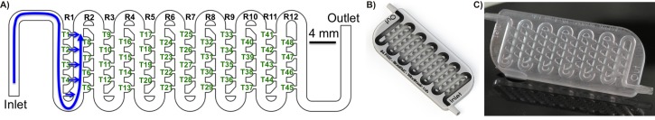
Monolithic microfluidic chip. (a) 2D CAD drawing. Detail shows miniaturized traps (T) located in an array of rows (R). Blue arrows denote direction of fluid flow inside fluidic circuitry, (b) 3D CAD rendered model of a microfluidic device, (c) chip-based prototype fabricated using a SLA process in a Watershed 11122XC resin.
We initially evaluated post-production protocols associated with additive manufacturing processes with particular attention paid to user-friendly methods suitable for rapid prototyping by non-engineering end-users in the biomedical field. Post-production processing protocols proved to be very straightforward for all SLA systems and required limited flushing with isopropyl alcohol using a syringe to remove non-polymerized resin residues followed by an UV-exposure in a standard biological tissue hood to harden the polymer (Fig. S2).29 Non-engineering personnel can easily perform both procedures using only standard equipment found in any biomedical laboratory. Mechanical polishing of the external surfaces was only required for resins such as Dreve Fototec 7150 Clear and Form Clear to render them optically transparent. In contrast to straightforward SLA techniques, procedures required for post-processing of MJM printed prototypes were found laborious with multiple steps to remove VisiJet S300 Support Wax from the millifluidic circuitry and mechanically clean the external surfaces (Fig. S2).29 This necessitated development of a highly customized protocol that proved to be neither reproducible nor user-friendly to average biomedical laboratory personnel. Moreover, we found that reliable and complete removal of support wax from monolithic and sealed millifluidic circuitries cannot be readily achieved (Fig. S2).29
Assessment of feature reproduction quality in dedicated resin materials was investigated with chip-based prototypes printed as monolithic and fully sealed chip-based devices, where the smallest feature of the prototype was the suction channel in the distal part of zebrafish traps channel (Fig. 2(a)). Resolution of additive fabrication compared favorably with other forms of rapid prototyping such as infra-red laser ablation in PMMA and soft lithography using PDMS. The suction channel designed in CAD to be 500 μm in width and was reproduced in PDMS, PMMA, VisiJet Crystal, Watershed 11122XC, Dreve Fototec 7150 Clear, VisiJet SL Clear, and Form Clear, averaging 654 ± 150 μm, 488 ± 51 μm, 522 ± 20 μm, 449 ± 6 μm, 492 ± 29 μm, 500 ± 8 μm, and 614 ± 26 μm, respectively. This corresponded to average deviations from a desired CAD geometry of 30%, 10%, 3%, 4%, 10%, 1.6%, 0%, and 23% for PDMS, PMMA, VisiJet Crystal, Watershed 11122XC, Dreve Fototec 7150 Clear, VisiJet SL Clear, and Form Clear, respectively. Overall traps and channel microstructures embedded within the chip were consistently fabricated with highest accuracy only in VisiJet SL Clear and Dreve Fototec 7150 Clear resins (deviation from desired geometry 0–2%) as seen in Fig. 2(a). Importantly, when prototypes were examined using optical microscopy, significant differences in internal channel surface roughness were readily observed between different resins utilized for manufacturing processes (Fig. 2(a)). They reflected incomplete polymerization during layer deposition and/or incomplete removal of unpolymerized resin during isopropanol post-production treatment. To validate these observations, prototypes were manufactured without top sealing surface thus enabling detailed assessment of the inner structure of the devices using scanning electron microscopy examination and quantitative 3D topographic surface mapping using optical profilometry (Figs. 2(b) and 2(c)). SEM and profilometry analyses revealed significant differences predominantly in layer deposition uniformity, surface roughness, and even surface porosity as depicted in Fig. 2(b) and Fig. S3.29 Surface topology of VisiJet SL Clear resin was closest to that achieved by soft lithography in PDMS with median height of 374 803 nm vs. 361 804 nm and median width of 35 342 nm vs. 23 160 nm, respectively (Figs. 2(c) and 2(d); Fig. S3).29
FIG. 2.

Physical characteristics of chip-based devices fabricated using additive manufacturing processes. (a) Feature definition and optical transparency assessed using optical stereomicroscopy. Zebrafish embryos immobilized inside hydrodynamic microtraps, (b) detailed feature definition and qualitative topographic surface analysis of a single microtrap using SEM, (c) quantitative 3D topographic surface analysis of a representative 500 × 500 μm section of a microfluidic channel fabricated using soft lithography in PDMS (left panel) and stereolithography in VisiJet SL Clear resin (right panel), (d) distribution of surface features roughness (median feature height in nanometers) depicted in (c).
Surface finish characteristics described above led to significant differences in optical clarity and performance. Optical qualities of the 3D printed chip-based devices were therefore tested in both brightfield and in popular biomedical applications fluorescent (FITC/GFP Ex 480 nm/Em 535 nm) modalities to uncover their suitability for imaging of biological specimens (Fig. 3). For those experiments, transgenic Fli1a:EGFP zebrafish embryos at 48 h post fertilization (hfp) were loaded into 3D printed chips. This particular fluorescent strain can be used to non-invasively observe the development of blood vessels expressing enhanced green fluorescent protein (EGFP) in endothelial cells (Fig. 3(a)). Fluorescent microscopy revealed significant autofluorescence and sub-standard optical transparency for the majority of 3D printed polymers. VisiJet SL Clear resin was found as the only suitable polymer for fabricating imaging-grade structures comparable to optical characteristics of PDMS or PMMA substrata (Fig. 3(a)). Interestingly, acquisition of stacked high-resolution confocal images could be reliably performed on a 3D printed prototype in the VisiJet SL Clear polymer as shown in Fig. 3(b). We concluded that the superior feature quality representation, optical transparency, and minimal autofluorescence VisiJet SL Clear polymer were deemed highly suitable for fabricating microfluidic devices that are used in conjunction with fluorescence imaging of biological specimens.
FIG. 3.

Optical transparency of 3D printed substrata for fluorescent microscopy imaging. (a) Epifluorescence imaging (GFP Ex 480 nm/Em 535 nm) of immobilized transgenic Fli1a:EGFP zebrafish embryos inside 3D printed microfluidic chip-based prototypes, (b) high-resolution stacked confocal imaging of immobilized, living transgenic Fli1a:EGFP zebrafish embryos on prototypes fabricated using soft lithography in PDMS (left panel) and stereolithography in VisiJet SL Clear resin (right panel).
Next, we set to investigate functional characteristics of additively manufactured prototypes. The design of the chip allowed for automatic trapping of individual embryos using hydrodynamic forces. Computational Fluid Dynamics (CFD) simulations predicted trapping efficiency close to 100%. We investigated how feature reproduction qualities affected performance of the devices under their normal operation. For this purpose, Fli1a:EGFP zebrafish embryos at 24 hfp were loaded into chip-based prototypes one-by-one in approximately five-second intervals at a volumetric flow rate up to 2 ml/min. Trapping efficiency was calculated as a number of captured embryos divided by the number of embryos injected into the LOC device. The results indicated that embryo trapping efficiency was greatly affected by feature reproduction and surface topology. Accordingly, trapping efficiencies in PDMS, PMMA, VisiJet Crystal, Watershed 11122XC, Dreve Fototec 7150 Clear, VisiJet SL Clear, and Form Clear prototypes averaged 81 ± 3%, 87 ± 2% μm, 48 ± 8%, 79 ± 1%, 100 ± 0% μm, 98 ± 2% μm, and 25 ± 5%, respectively (Fig. S4).29 Residues of support wax caused the exceedingly low trapping results achieved by devices made using MJM process in VisiJet Crystal resin. In contrast, low trapping efficiency data from Form Clear resin printed chips reflected an overall low quality of feature reproduction and significant surface roughness due to a poor layer composition. However, the superior embryo trapping achieved by Dreve Fototec 7150 Clear and VisiJet SL Clear devices stemmed from superior feature reproduction (deviation from desired geometry 0–2%) and minimal surface roughness as determined by SEM and profilometry.
Finally, we set to validate biocompatibility of 3D printed microenvironments for long-term bioassays on living zebrafish embryos. The embryonic developmental stage is considered to be the most sensitive to environmental perturbations and can be readily applied to assess impacts of any potential toxic effects of chemicals and solid substrata.28,31 For this purpose, wild-type zebrafish embryos at 6 hfp were loaded into chip-based prototypes and perfused at a flow rate of 0.4 ml/min for up to 72 h. Strikingly, we observed significant toxicity effects of both VisiJet Crystal and Form Clear resins as evidenced by 95 ± 7%, and 85 ± 21% of the embryos were severely apoptotic or dead at 72 h, respectively (Fig. 4). Interestingly, toxicity was not observed during first 48 h of examination suggesting cumulative chronic rather than acute responses to water soluble photocurable polymer leachates. The remaining polymers did not exhibit statistically significant differences in embryo survival for up to 72 h (p < 0.05; Fig. 4). However, in surviving embryos, we observed significant developmental abnormalities such as pigmentation loss, tail detachment, and pericardial oedema for all polymers but VisiJet SL Clear (Fig. 4 and Fig. S5).29 The cumulative survival of embryos in control PDMS and PMMA chips was over 95% with no developmental abnormalities recorded (Fig. 4).
FIG. 4.

Biocompatibility of 3D printed microenvironments for long-term bioassays on living zebrafish embryos. Matrix chart depicts cumulative teratogenic effects during a standard zebrafish embryo toxicity (FET) test performed in at least 3 independent experiments. CTR: control; MJM: multi-jet-modelling; SLA: stereolithography; HI: hatching inhibition; TA: trunk abnormalities; PO: pericardial oedema; HR: heart rate abnormalities.
CONCLUSIONS
The main goal of this work was to demonstrate the feasibility of using additive manufacturing to accelerate prototyping of optically transparent and biocompatible chip-based devices for research application employing small specimens such as zebrafish embryos. Majority of the selected additive manufacturing technologies were capable of printing with resolutions of approximately 100 μm in the x-y dimension and to 50 μm in the z dimension. Therefore, we chose to explore their applicability for devices with channel minimum cross-section dimensions ranging from 500 to 1500 μm that are perfectly suitable for larger metazoan model organisms. As such, these devices were more properly termed millifluidic rather than true microfluidic systems. Miniaturized millifluidic channels of these dimensions were found to be particularly suitable for rapid post-processing including drainage and removal of uncured polymer precursors. This enabled us to achieve very low deviation from the desired geometry of the channels.
To the best of our knowledge, this work is so far the most comprehensive side-by-side evaluation of several MJM and SLA 3D printing technologies for making biocompatible millifluidic devices. In our study, we addressed resolution, materials, surface topology, optical clarity, autofluorescence, and biocompatibility concerns that have until now not been fully explored in prior studies on the subject. The presented data and the specific millifluidic application demonstrate the significant potential SLA for rapid design-to-chip one-step manufacturing of LOC devices. Especially, the capability to perform rapid design troubleshooting in the virtual space and perform iterative prototyping without device-to-device variability during assembly is a compelling argument towards adopting SLA in the Lab-on-a-Chip field. We conclude that compared with other rapid prototyping technologies, such as, for example, soft lithography and infrared laser micromachining in PMMA, selected SLA technologies can achieve user-friendly and rapid production of prototypes, superior feature reproduction quality, better levels of device function, and optical transparency comparable to PDMS and PMMA. In our opinion, SLA is also more convenient as a rapid prototyping tool as it allows for producing complex 3D architectures and monolithic devices with build-in fluidic interconnections that would not be achievable with standard PDMS replica molding. Furthermore, developments improving 3D printing resolutions and further reducing costs of equipment are expected to expand the applications of additive manufacturing in biomicrofluidic applications in the near future.10,16
We postulate that caution needs to be taken, however, as a vast majority of tested SLA and MJM resins were found toxic and/or caused significant developmental abnormalities as evidenced by the highly sensitive zebrafish embryo toxicity biotest. Although we evaluated only selected photocurable resins and printer systems on one biological model, the data nevertheless highlight a potential biocompatibility problem of polymers commonly used in additive manufacturing. We conclude that as SLA technology slowly matures, it can become both feasible and reliable platform to fabricate microfluidic chip-based devices without any need to access expensive clean room environments. More studies need to be performed to evaluate biocompatibility and chemical properties of existing polymers in different biological assays, while at the same time, work should also begin on development of non-toxic photocurable polymer chemistries specifically aimed at biological and biomedical applications.
ACKNOWLEDGMENTS
This work was supported by the Australian Research Council DECRA under Grant No. DE130101046 (D.W.), Vice-Chancellor's Senior Research Fellowship, RMIT University, Australia (D.W.), Mobility Scholarship, School of Engineering, University of Glasgow, Scotland (N.M.), NHMRC project GNT1068411 (J.K.), and Eva and Les Erdi foundation (J.K.). We acknowledge assistance of RMIT Micro Nano Research Facility (MNRF) during optical profilometry, RMIT Microscopy and Microanalysis Facility (RMMF) during SEM imaging experiments, Monash University FishCore in zebrafish breeding and embryo culture, and also Monash University Micro Imaging (MMI) facility during confocal microscopy studies.
References
- 1. Whitesides G. M., Nature 442(7101), 368–373 (2006). 10.1038/nature05058 [DOI] [PubMed] [Google Scholar]
- 2. Weibel D. B. and Whitesides G. M., Curr. Opin. Chem. Biol. 10(6), 584–591 (2006). 10.1016/j.cbpa.2006.10.016 [DOI] [PubMed] [Google Scholar]
- 3. Becker H., Lab Chip 9(15), 2119–2122 (2009). 10.1039/b911553f [DOI] [PubMed] [Google Scholar]
- 4. Skommer J. and Wlodkowic D., Expert Opin. Drug Discovery 10(3), 231–244 (2015). 10.1517/17460441.2015.1001736 [DOI] [PubMed] [Google Scholar]
- 5. Zhu F., Skommer J., Huang Y., Akagi J., Adams D., Levin M., Hall C. J., Crosier P. S., and Wlodkowic D., Cytometry, Part A 85(11), 921–932 (2014) 10.1002/cyto.a.22571. [DOI] [PMC free article] [PubMed] [Google Scholar]
- 6. Baratchi S., Khoshmanesh K., Sacristan C., Depoil D., Wlodkowic D., McIntyre P., and Mitchell A., Biotechnol. Adv. 32(2), 333–346 (2014). 10.1016/j.biotechadv.2013.11.008 [DOI] [PubMed] [Google Scholar]
- 7. Wlodkowic D., Khoshmanesh K., Akagi J., Williams D. E., and Cooper J. M., Cytometry, Part A 79A(10), 799–813 (2011). 10.1002/cyto.a.21070 [DOI] [PubMed] [Google Scholar]
- 8. Akagi J., Zhu F., Hall C. J., Crosier K. E., Crosier P. S., and Wlodkowic D., Cytometry, Part A 85(6), 537–547 (2014). 10.1002/cyto.a.22464 [DOI] [PubMed] [Google Scholar]
- 9. Khoshmanesh K., Akagi J., Hall C. J., Crosier K. E., Crosier P. S., Cooper J. M., and Wlodkowic D., Biomicrofluidics 6(2), 24102–2410214 (2012). 10.1063/1.3699971 [DOI] [PMC free article] [PubMed] [Google Scholar]
- 10. Au A. K., Lee W., and Folch A., Lab Chip 14(7), 1294–1301 (2014). 10.1039/C3LC51360B [DOI] [PMC free article] [PubMed] [Google Scholar]
- 11. Waldbaur A., Rapp H., Lange K., and Rapp B. E., Anal. Methods 3(12), 2681–2716 (2011). 10.1039/c1ay05253e [DOI] [Google Scholar]
- 12. Wlodkowic D., Faley S., Skommer J., McGuinness D., and Cooper J. M., Anal. Chem 81(23), 9828–9833 (2009). 10.1021/ac902010s [DOI] [PubMed] [Google Scholar]
- 13. Sia S. K. and Whitesides G. M., Electrophoresis 24(21), 3563–3576 (2003). 10.1002/elps.200305584 [DOI] [PubMed] [Google Scholar]
- 14. Shallan A. I., Smejkal P., Corban M., Guijt R. M., and Breadmore M. C., Anal. Chem. 86(6), 3124–3130 (2014). 10.1021/ac4041857 [DOI] [PubMed] [Google Scholar]
- 15. Rogers C. I., Qaderi K., Woolley A. T., and Nordin G. P., Biomicrofluidics 9(1), 016501 (2015). 10.1063/1.4905840 [DOI] [PMC free article] [PubMed] [Google Scholar]
- 16. Tseng P., Murray C., Kim D., and Di Carlo D., Lab Chip 14(9), 1491–1495 (2014). 10.1039/c4lc90023e [DOI] [PubMed] [Google Scholar]
- 17. Conner B. P., Manogharan G. P., Martof A. N., Rodomsky L. M., Rodomsky C. M., Jordan D. C., and Limperos J. W., Addit. Manuf. 1–4(1), 64–76 (2014). 10.1016/j.addma.2014.08.005 [DOI] [Google Scholar]
- 18. Baden T., Chagas A. M., Gage G., Marzullo T., Prieto-Godino L. L., and Euler T., PLoS Biol. 13(3), e1002086 (2015). 10.1371/journal.pbio.1002086 [DOI] [PMC free article] [PubMed] [Google Scholar]
- 19. Lantada A. D. and Morgado P. L., Annu. Rev. Biomed. Eng. 14, 73–96 (2012). 10.1146/annurev-bioeng-071811-150112 [DOI] [PubMed] [Google Scholar]
- 20. van Noort R., Dent. Mater. 28(1), 3–12 (2012). 10.1016/j.dental.2011.10.014 [DOI] [PubMed] [Google Scholar]
- 21. Li M. G., Tian X. Y., and Chen X. B., Biofabrication 1(3), 032001 (2009) 10.1088/1758-5082/1/3/032001. [DOI] [PubMed] [Google Scholar]
- 22. Infuehr R., Pucher N., Heller C., Lichtenegger H., Liska R., Schmidt V., Kuna L., Haase A., and Stampfl J., Appl. Surf. Sci. 254(4), 836–840 (2007). 10.1016/j.apsusc.2007.08.011 [DOI] [Google Scholar]
- 23. McCullough E. J. and Yadavalli V. K., J. Mater. Process. Technol. 213(6), 947–954 (2013). 10.1016/j.jmatprotec.2012.12.015 [DOI] [Google Scholar]
- 24. Kitson P. J., Rosnes M. H., Sans V., Dragone V., and Cronin L., Lab Chip 12(18), 3267–3271 (2012). 10.1039/c2lc40761b [DOI] [PubMed] [Google Scholar]
- 25. Yuen P. K., Lab Chip 8(8), 1374–1378 (2008). 10.1039/b805086d [DOI] [PubMed] [Google Scholar]
- 26. Bhargava K. C., Thompson B., and Malmstadt N., Proc. Natl. Acad. Sci. U. S. A. 111(42), 15013–15018 (2014). 10.1073/pnas.1414764111 [DOI] [PMC free article] [PubMed] [Google Scholar]
- 27. Akagi J., Khoshmanesh K., Evans B., Hall C. J., Crosier K. E., Cooper J. M., Crosier P. S., and Wlodkowic D., PLoS One 7(5), e36630 (2012). 10.1371/journal.pone.0036630 [DOI] [PMC free article] [PubMed] [Google Scholar]
- 28.OECD, in “ Section 2: Effects on biotic systems,” OECD Guidelines for the Testing of Chemicals ( OECD, 2013). [Google Scholar]
- 29.See supplementary material at http://dx.doi.org/10.1063/1.4927379E-BIOMGB-9-009504 for supplementary results and data.
- 30. Wang K. I. K., Salcic Z., Yeh J., Akagi J., Zhu F., Hall C. J., Crosier K. E., Crosier P. S., and Wlodkowic D., Biosens. Bioelectron. 48, 188–196 (2013). 10.1016/j.bios.2013.04.033 [DOI] [PubMed] [Google Scholar]
- 31. Lammer E., Carr G. J., Wendler K., Rawlings J. M., Belanger S. E., and Braunbeck T., Comp. Biochem. Physiol., Part C: Toxicol. Pharmacol. 149(2), 196–209 (2009). 10.1016/j.cbpc.2008.11.006 [DOI] [PubMed] [Google Scholar]
Associated Data
This section collects any data citations, data availability statements, or supplementary materials included in this article.
Data Citations
- See supplementary material at http://dx.doi.org/10.1063/1.4927379E-BIOMGB-9-009504 for supplementary results and data.