Abstract.
Optical recording facilitates monitoring the activity of a large neural network at the cellular scale, but the analysis and interpretation of the collected data remain challenging. Here, we present a MATLAB-based toolbox, named NeuroCa, for the automated processing and quantitative analysis of large-scale calcium imaging data. Our tool includes several computational algorithms to extract the calcium spike trains of individual neurons from the calcium imaging data in an automatic fashion. Two algorithms were developed to decompose the imaging data into the activity of individual cells and subsequently detect calcium spikes from each neuronal signal. Applying our method to dense networks in dissociated cultures, we were able to obtain the calcium spike trains of neurons in a few minutes. Further analyses using these data permitted the quantification of neuronal responses to chemical stimuli as well as functional mapping of spatiotemporal patterns in neuronal firing within the spontaneous, synchronous activity of a large network. These results demonstrate that our method not only automates time-consuming, labor-intensive tasks in the analysis of neural data obtained using optical recording techniques but also provides a systematic way to visualize and quantify the collective dynamics of a network in terms of its cellular elements.
Keywords: calcium imaging, optophysiology, neural activity imaging, network bursts, neural signal processing
1. Introduction
The sophisticated functions of the brain are governed by the coordinated activity of multiple neurons.1–3 Therefore, deciphering the spatial and temporal patterns of neuronal activity in a large population is essential to understand the operating principles of neural circuits.4 Optical recording using activity-dependent fluorescence sensors, particularly calcium indicators, is a powerful method due to its superior resolution in space by comparison with electrophysiological approaches.5 Nowadays, it becomes feasible to simultaneously capture the activity of hundreds and thousands of individual cells from dissociated cultures,6,7 tissue slices,8–10 or the brain of living animals,11–13 providing the glimpses of collective neural dynamics. Although the optical acquisition of neural activity data has been remarkably advanced owing to the efforts in developing genetic sensors14–16 and imaging techniques,17,18 it remains challenging to analyze the collected image datasets due to their massive size and complexity.
The analysis of calcium imaging data requires spike sorting to isolate the signals of individual cells and quantitative representation of their activity patterns. However, computational tools are often unavailable that supports automated processing and quantitative analyses of the imaging data. As a result, typical approaches have relied on the manual annotation of cells19–21 and qualitative comparison of their fluorescent signals13,22,23 despite the consumption of considerable time and human labor. Recently, several computational methods were suggested to automate cell identification24–27 and spike inference28–32 from the imaging data. However, additional programming still requires for integrating and optimizing these algorithms for practical use in data analysis. Additionally, even though the activities of individual neurons are identified, visualizing and deriving meaningful features of their ensemble activity are still challenging due to the deficiency of suitable and standardized methods.33,34 Thus, developing a comprehensive software package for automated processing and quantitative analyses of calcium imaging data would be beneficial for large-scale neurophysiological studies.
In this work, we have developed a new open-source, stand-alone toolbox called NeuroCa. This program includes our new algorithms for cell identification and spike detection from the calcium imaging data, and also allows the quantification and visualization of neuronal activity patterns in a large network (Fig. 1). To detect individual cells, we applied a morphological feature extraction method based on the circular Hough transform to the image set. Our method enabled isolating the regions of individual cell bodies with high efficiency, resulting in the fluorescence signals of each cell as “multi-channel neural data.” To extract the calcium spikes of each neuron, we devised a procedure that corrected the background trend of cellular signals by using curve fitting and subsequently detected calcium spikes by using deconvolution with data-driven kernels. Using dissociated cultures of cortical neurons, we demonstrated that the reconstructed spike trains of individual neurons could be utilized not only to calculate the quantitative measures of cellular activity, but also to estimate the functional connectivity of the neural circuits. In particular, we attempted to exploit neuronal calcium spike trains to infer the firing patterns in the synchronous activity of a large network for demonstrating the utility of our approach to dissect the spatial and temporal organization of neuronal circuits at cellular scale.
Fig. 1.
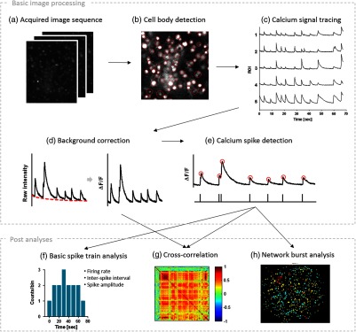
Analytical procedure of calcium imaging data. (a,b) The image sequence is decomposed into the regions of individual cell bodies by our cell body detection algorithm, and (c) the fluorescence signal of each region of interest (ROI) was calculated by averaging the mean intensity of each region at each frame. From the calcium signals, (d) the baseline fluctuation was compensated by our curve fitting method and (e) calcium spikes were detected. (f, g) The constructed spike train data could be further used for the analysis of neural activity (f) and functional connectivity (g). (h) We have focused on investigating the neuronal firing patterns in synchronous network bursts that are spontaneously emerged from the dissociated neural networks.
2. Methods
2.1. Cell Culture
Cortical neurons were cultured to construct functionally active neural networks in vitro. The cortical tissues were dissected from E18 SD rats (Koatech, Republic of Korea) and immersed into HBSS (14175, Gibco, California). After dissociating the tissue into the single cells, we centrifuged the suspension at 1000 rpm for 2 min. Supernatant was then gently removed, and the plating medium [Neurobasal medium (21103, Gibco, California) supplemented with B27 (17504-044, Gibco, California), 2 mM GlutaMAX-1 (35050, Gibco, California, L-glutamate (L-Glutamic acid, nonanimal source, G8415, Sigma, Missori, and 1% (v/v) penicillin-streptomycin (15140, Gibco, California)] was re-filled to suspend cells. Cells were cultured on the substrate with the density of , and half of medium was changed with the maintenance medium (as same as the plating medium without L-glutamate) twice a week. All procedures of cultivation were performed according to the approved animal use protocols of the KAIST Institutional Animal Care and Use Committee.
2.2. Calcium Imaging
We used a commercial calcium indicator, Oregon green BAPTA-1 (OGB-1; ; O6807, Molecular Probes®, California), for measuring neural activities. The stock solution of the calcium indicator was made of OGB-1 (50 mg), of dimethyl sulfoxide (DMSO; D4540, Sigma, Missouri), and of F127 solution [Pluronic® F-127; 20% (w/v) in DMSO; P2443, Sigma, Missouri]. We also used buffered artificial cerebrospinal fluid (bACSF) composed of (25 mM), D-glucose (25 mM), NaCl (125 mM), KCl (2.5 mM), (1.25 mM), (1 mM), and (2 mM) in third distilled water and supplemented with 10 mM of HEPES. Prior to the preparation of imaging, all materials were heated in an incubator (37°C, 5%).
To introduce the calcium indicator to the samples, the stock solution was added to bACSF and gently mixed by pipetting (the final concentration of OGB-1 was 2.5 mM). After aspirating the whole medium in the culture, we added the diluted indicator solution to the sample for 30 min of dye loading. Next, the solution was aspirated again and washed with fresh bACSF two or three times. The sample was soaked in fresh bACSF for 30 min again for stabilization and then ready to be measured.
The imaging setup was composed of an upright microscope (BX51, Olympus, Japan) with a light-emitting diode (LED) source (SOLA SM, Lumencor, Oregon), a camera (sCMOS Neo, Andor Technology, UK), and a heating plate with a temperature controller (TC01, Multichannel Systems, Germany) for maintaining 37°C during imaging. We acquired images with the frame rate of about 32 Hz and the field-of-view (FOV) of about .
The computer for acquiring real-time image data was composed of Intel® Core i5-2400 processor (3.1 GHz; motherboard: Asus P8H67) supporting SATA and 16 GB of memory. For achieving fast and stable data acquisition, we connected solid-state drives (SSDs; 840 Pro, Samsung, Republic of Korea). In all calcium imaging experiments, image data were collected via custom-made software based on Andor SDK3 (Andor Technology, UK).
2.3. Chemical Stimulation
Several agonists of neurotransmitter receptors, such as N-methyl-D-aspartic acid (NMDA; M3262, Sigma, Missouri), -amino-3-hydroxy-5-methyl-4-isoxazolepropionic acid (AMPA; Asc-130, Ascent Scientific), and -aminobutyric acid (GABA; A2129, Sigma, Missouri), and an antagonist of GABAergic receptor (bicuculline; Tocris), were used to change neural activity. NMDA, GABA, and bicuculline were dissolved into bACSF with of concentration and AMPA was dissolved into bACSF with of concentration. After baseline recording with the culture immersed in pure bACSF, half of the bath solution was replaced with the same amount of drug-containing solution; therefore, the final concentration of NMDA, GABA, and bicuculline was , and that of AMPA was . All the bath solution was aspired for washing out, and fresh bACSF heated up to 37°C in advance was filled in the culture.
2.4. Cell Body Detection
To correct the imbalance illumination and enhance the contrast level, top-hat filtering and contrast adjustment were applied to the image data. Next, circular Hough transform (CHT) was applied to the corrected image to detect all circular elements (here, somata) as independent regions of interest (MATLAB function: imfindcircles). This step gave rise to the center and radius of each region of interest (ROI) that is available to construct the binary mask image. We used radius 1 to fill the ROI area instead of the original value to avoid the overlapping between different ROIs. Furthermore, to prevent missing cells that are not activated at the very first snapshot, we repeated this procedure in the first 200 images of a sequence (if the total number of images were less than 200, all the images were used) and overlapped each mask into one by “OR” operation. Using this final mask, we could obtain the spatial information (center and radius) of each circular element that outlined the somata as ROIs one-by-one and traced the mean intensity of pixels in each ROI over time as a calcium signal.
2.5. Photobleaching Correction
To calculate , we estimated the baseline, , from each fluorescence calcium signal by double curve fitting. First, the signal was fitted with the exponential decay function, and we built the error histogram between the fitted curve and the raw signal (first fitting). By fitting the Gaussian distribution to this histogram, we defined the range of noise values as the full-width half-maximum (FWHM) of the histogram. Then, only considering these noise values, we fitted the signal once again with a new exponential decay curve to find the baseline signal. Using this signal, we finally calculated to obtain the cellular signals with zero baseline.
2.6. Calcium Spike Detection
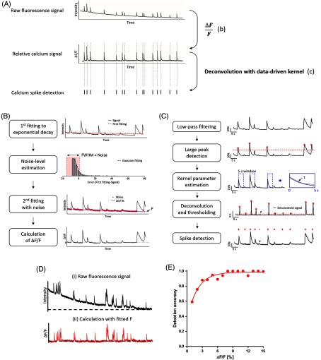
To detect calcium spikes from each signal, we used the deconvolution method suggested by Yaksi and Friedrich35 with slightly modified steps. First, we used a low-pass Butterworth filter (second order) to attenuate noisy fluctuation in the calcium signal (cutoff frequency: 2 Hz). Subsequently, the large peaks in this filtered signal were simply detected by finding the local maxima above the threshold (3 to 5 times the standard deviation), and the signal was segmented with the 5-s window from the peaks. All the segments were aligned to zero and averaged to create a representative form of calcium spikes for this signal. Then, we used this averaged spike to estimate the decay time [ in Fig. 4(c), third graph] of the kernel, . The signal was deconvolved using inverse filtering of this kernel, and the peaks of this trace above the threshold were detected to extract the timestamps.
Fig. 4.
Spike detection algorithm including baseline estimation and deconvolution with data-driven kernels. (A) To detect the calcium spikes from the fluorescence signal of each cell, we used a two-step procedure: (b) the correction of baseline level and (c) deconvolution with data-driven kernels. (B) In the first step for removing the baseline trend, the raw signal was fitted to the exponential function (red dashed line) at first (top graph). Then, the noise level was estimated by means of Gaussian distribution fitting (black dashed line) to the error histogram (second graph). The values within the full-width half-maximum (FWHM) were considered as noise. Using only noise values (red dots), the second fitting was carried out to find more precise baseline (third graph). This second fitted signal was finally concerned as the baseline (blue dashed line indicated as “F”). The relative ratio of fluorescence intensity change to the baseline was calculated (bottom graph). (C) From this corrected signal, we could detect calcium spikes. To reduce the noise, we smoothed the signal using low-pass filter (top graph), and detect only large peaks (marked with red circles) by simply thresholding (red dashed line) the filtered signal (second graph). Using a 5 s window (blue dashed rectangles), we collected the large spikes and found the parameter, , to determine the data-driven kernel (third graph). Then we deconvolved the filtered signal using this kernel and detected the peaks above the threshold (red dashed line; fourth graph; red arrowheads: hits, black arrowhead: miss). These peaks were then concerned as the timing of spikes (bottom graph; red ticks: detected spikes, gray tick: missed spike). (D) Validation of the ability of our method. Raw neuronal calcium signals (I) were corrected by our curve fitting method (ii). (E) The detection accuracy of our method from corrected signals with respect to the manual inspection was measured. Each point represents the accuracy of spike detection in the amplitude range of to less than .
2.7. Synchronous Activity Detection
We simply detected the timing of network-wide synchrony from the calcium spike trains of all ROIs in one FOV. The first step of this procedure was to obtain the network burst profile by calculating the ratio of activated ROIs to the total number of ROIs at each frame. The peaks of this profile above the threshold (here, we used 0.2–0.3 in most cases) were detected as “network burst points.” At each network burst point, we defined the duration of this burst as between two frames at which all cells were silent just before and after the burst point.
2.8. Statistical Analysis
Using the temporal ROI sequences of a network burst, we implemented the nonparametric statistical analysis based on the Kendall’s rank correlation for evaluating the association and consistency of the temporal orders.8 The coefficient, , indicates the association between two ranking orders as follows:
| (1) |
where and are the number of concordant and disconcordant pairs, respectively; and is the number of the rank. As the firing order of several neurons is usually tied due to the limited temporal resolution, the additional terms, and , were complemented with the number of concurrently fired ROIs in ’th order. In this measure, can span from 0 to 1; if the order of two sequences is exactly the same, is 1. The pairwise comparison of all pairs of ROIs could be then clustered to identify the patterns of inter-burst propagation in the similar way to the correlation analysis. To create the matrix of , we defined the distance, , between two temporal orders in ’th and ’th bursts, as follows:
| (2) |
where is of ’th and ’th bursts.
3. Results
3.1. Procedure for Data Processing and Analysis
Our approach was aimed at converting the two-dimensional images of optical neural data to the collection of neuronal calcium spike trains (“data processing”) and using these spike data for the various analyses of neural dynamics (“data analysis”). To achieve the first goal of data processing, we developed a step-by-step procedure (“Basic image processing” in Fig. 1); the first step was to identify the regions of individual cell bodies (“Cell body detection” in Fig. 1). Then, the mean fluorescence intensity of each ROI over time (frame) was traced to extract cellular signals (“Calcium signal tracing” in Fig. 1). These signals were subsequently converted into the relative change of intensity after automatic baseline correction (“Background correction” in Fig. 1), and the transients of calcium signals were detected as “calcium spikes” whose peaks imply the timing of cellular firing (“Calcium spike detection” in Fig. 1).
The neuronal spike trains derived from the imaging data were then used to analyze neural activities with a multitude of quantitative measures (“Post analysis” in Fig. 1). The temporal patterns of neural activity were quantified by using mean firing rate (MFR), inter-spike interval (ISI), or the amplitude of calcium spikes (“Basic spike train analysis” in Fig. 1). The functional connectivity between neurons was estimated by calculating pair-wise cross-correlation (“Cross-correlation” in Fig. 1). Finally, we utilized neuronal spike trains to reveal the spatiotemporal firing patterns in the synchronous activity of a network. (“Network burst analysis” in Fig. 1).
3.2. Sorting of Cellular Signals
To automatically identify each cell body from an image where hundreds or thousands of cells were captured, we used the elliptical morphology of cell bodies. Following the preprocessing of images to enhance the contrast between cellular regions and background [“Adjusted contrast” in Fig. 2(a)], we applied CHT36 to the calcium imaging data in order to isolate circular elements that corresponded to the cell bodies [“Detected somata” in Fig. 2(a); for further details, see Methods section]. Despite the coexistence of thin linear structures (neurites) with similar brightness, CHT could detect circular regions with their location and size, thereby isolating each cell body as an ROI [ROI; outlined with red circles in Fig. 2(a)]. Subsequently, the mean fluorescence intensity of each ROI was traced in all the frames of the image set as the signal of each cell [Fig. 2(b)].
Fig. 2.
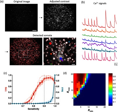
Cell body detection and parameter optimization. (a) The procedure of the cell body detection from the image sequences. (a) The image (“Original image”) was preprocessed by tophat filtering and contrast level adjustment (“Adjusted contrast”) and used to detect cells by applying circular Hough transform (CHT) (“Detected somata”). (b) Examples of the raw fluorescence calcium signal traced from each identified cell in (a). These signals were traced from seven neurons selectively marked with the same color in (a). (c) True positive rate [(TPR); orange] and false positive rate; blue versus sensitivity (the parameter for determining the threshold of circularity) was plotted (; ). The dashed line indicates the sensitivity of 0.9. (d) The color-coded image of detection efficiency depending on the combination of minimum and maximum radii. The scale bar in “Original image” and “Detected somata” of (a) indicates and , respectively.
Using CHT to the cell body identification requires the predetermination of two parameters: sensitivity and the range of radius. The sensitivity of CHT determines how much rounded objects would be detected; the larger this value is, the more circles CHT can detect including distorted ones. The second parameter, the range of radius, constrains the size of detectable objects. To optimize these parameters, we compared the number of cells detected by CHT with manual annotation. We used 10 different images of dye-loaded neural networks in dissociated cultures and manually counted the total number of cells in each image ( cells). The true positive rate (TPR), indicating the ratio of automatically detected cells to the manually identified ones, gradually escalated as the sensitivity increased. The maximum TPR was achieved when the sensitivity was in the range of 0.90–0.98 [Fig. 2(c)]. On the other hand, the false positive rate, calculated by the ratio of false alarms at each sensitivity to the maximum likelihood (when the sensitivity was 1), did not change at the sensitivity of less than 0.9 but drastically increased above this value [Fig. 2(c)]. Thus, the optimal sensitivity was set to be 0.9 for the accurate detection of cell bodies [Fig. 2(c), indicated by a black dashed line].
With the optimal sensitivity of 0.9, we calculated TPR as the measure of detection accuracy in varying ranges of radius. All paired combinations from 3 to 31 pixels, which corresponded to about to in diameter, were examined. Our examination showed that the best result of our algorithm was achieved at the range of 5–6 pixels for the minimum radius and 15–31 pixels for the maximum radius with the detection accuracy of [Fig. 2(d)]. For the analysis of real data, we chose 5–15 pixels as the optimal range of the radius. This pixel-range corresponds to in diameter for our microscopic setup (objective: 20x, image resolution: ) such that the optimal range for other imaging data could be converted, according to the spatial resolution of the microscopic setup.
Next, using the optimized parameters, we assessed how many cells our algorithm can detect and how well it can separate a cellular cluster into single cells. For the quantitative evaluation, we measured the detection accuracy of our method and compared it with that of a simple thresholding method. The simple thresholding method isolated the connected pixels brighter than their surroundings as one ROI. As a result, CHT showed superior performance of individual cell separation than the thresholding method [Fig. 3(a)]. Compared to the manual detection, CHT could identify more cells () than simple thresholding [; Fig. 3(b)]. In addition, CHT could select individual cells as different ROIs, but the simple thresholding method could not separate them from the bright region in which cells were too close to each other or formed clusters [Figs. 3(a) and 3(c)]. More than 95% of the ROIs contained only one cell by applying CHT [Fig. 3(c), right], but only half of ROIs did in case of the simple thresholding [Fig. 3(c), left]. Furthermore, the distribution of ROI diameters detected by using CHT also showed that it was comparable to the size of cell bodies [about in diameter;37 Fig. 3(d)]. In addition, the minimum distance between two ROIs was , implying the possibility of our method to distinguish two overlapping cells as different ROIs. As a consequence, all the results indicated that our algorithm based on CHT had the outstanding ability to not only identify most of the cells but also isolate each of them in calcium imaging data.
Fig. 3.
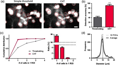
CHT identifies most of the cell bodies as a single ROI. (a) The same image processed with simple thresholding and CHT algorithm. Each area outlined a red curve in simple threshold or circle in CHT indicates each ROI. (b) The ratio of identified ROI numbers to the number of cells that were manually detected (; ; ). (c) The cumulative distribution of the number of cells detected as one ROI (left) with simple thresholding (gray) and CHT (magenta) and the normalized histogram of CHT (right; ; ). (d) The distribution of ROI diameters in 10 field-of-views (gray) and average (black). The scale bar in (a) indicates .
3.3. Calcium Spike Detection from Fluorescence Signals
After extracting the mean fluorescence intensity of each ROI from the image sequence, we applied two operations to the fluorescence signal in order to reconstruct the spike train of each neuron [Fig. 4(a)]. First, the raw signal was converted into the relative value of the baseline (, where is the baseline level). Second, the rapid transients of calcium signals were detected to infer the timing of the action potential firing.
In the first step, precisely estimating the trend of the baseline is essential to correct each cellular signal, as the background fluorescence intensity was not consistent but often decreased over time mostly due to photobleaching. To correct this inconsistent decay, we developed a method based on curve fitting for estimating the baseline from each cellular signal [Fig. 4(b)]. First, we fit an exponential decay function to the original fluorescence signal [Fig. 4(b), top graph]. The histogram of the errors between the original and fitted values was then fit to Gaussian distribution to determine the noise level of the signal; we decided the noise range as the FWHM of this distribution. By only using the noise values for the second fitting of a new exponential decay function, we were able to estimate the background trend () for each ROI. The calcium signal of each cell () was finally calculated as follows:
| (3) |
where was the mean fluorescence intensity of each ROI at the ’th frame [Fig. 4(b), bottom graph].
The next step was to detect spikes from the corrected signals. Considering the fluorescence signal as the superposition of calcium spikes that follow the instantaneous increase and subsequent exponential decay,38 we designed a new simple method based on deconvolution,35 which used a kernel of calcium spikes derived from the real data [Fig. 4(c)]. The signal was smoothed using a low-pass filter to attenuate the fast, noisy component [second Butterworth; Fig. 4(c), top graph]. Then the large peaks were detected from the signal with thresholding [Fig. 4(c), the second graph]. By averaging these large spikes, we obtained a template of a spike for each calcium signal and fitted the exponential decay curve to construct a kernel [Fig. 4(c), the third graph]. With this data-driven kernel, the signal was subsequently deconvolved [Fig. 4(c), the fourth graph]. Finally, we detected the peaks of the deconvolved signal above the threshold that corresponded to calcium spikes [Fig. 4(c), bottom graph; for further details, see Methods section].
Our calculation based on curve fitting successfully corrected the decreasing trend of background without the distortion of fast calcium spikes [Fig. 4(d)]. Furthermore, we validated the ability of our algorithm to detect calcium spikes by measuring the detection accuracy with respect to the manual annotation according to the spike amplitude [Fig. 4(e)]. Our method was capable of detecting more than 90% of the spikes that have the amplitude of . These results demonstrated that our method based on the combination of noise-estimated curve fitting and deconvolution with a data-driven kernel was efficient to detect calcium spikes, particularly the small ones that may represent a single action potential.8,29,39
3.4. Reconstruction of Neuronal Spike Trains from a Large-Scale Network
To demonstrate the applicability of our tool, we used the calcium imaging data of spontaneous neural activity measured from cultured neural networks (Fig. 5). In our experimental setup, we captured a large area () of the network in which 500–1000 cells were simultaneously recorded [Fig. 5(a)]. Using our method, we were able to extract the activity of each cell in the form of spike trains [exemplified in Figs. 5(b) and 5(b’)].
Fig. 5.
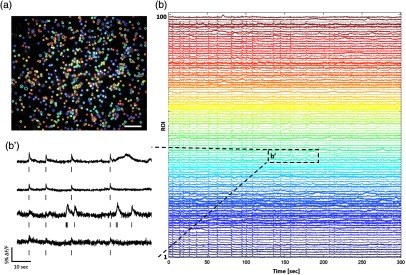
Although the neurons were cultured in the serum-free condition, glial cells often emerged in the mature networks ( weeks in vitro). Some of the ROIs showed slow transients of astrocytes, and others contained the mixed features of neuronal spikes and glia transients in some cases that two different cells were overlapped. Among 5989 cells in nine networks, neuronal, glia, and mixed signals were 62.0%, 6.21%, and 20.7%, respectively. The rest of the ROIs were silent (11.1%). The results indicated that our algorithm could identify not only neuronal cell bodies, but also glia cells with the mean discrimination accuracy of 79.3%, which was comparable to the previous methods.24,33 In addition, our algorithm was also able to identify silent cells, which were vital to represent neural activity in behaviors40 and cognitive functions.41
3.5. Post Analysis 1: Quantification of Neuronal Activities
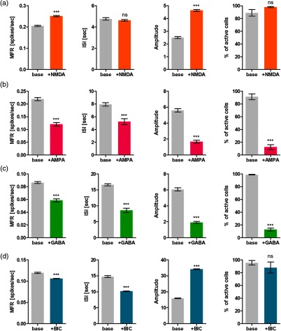
Using our method, we quantitatively analyzed the responses of cultured neurons to the controlled extracellular environment by pharmacological treatment (Fig. 6). We used four different chemicals to control neural activity; NMDA and AMPA are the agonists of excitatory glutamatergic receptors, and GABA and bicuculline are the agonist and antagonist of inhibitory GABAergic receptors, respectively. As we reconstructed spike trains from the image datasets, we could directly calculate the MFR, ISI, the mean amplitude of calcium spikes, and the ratio of active cells as the measure of cellular activity before and after treatment.
Fig. 6.
Quantitative analyses of the effect of chemical stimulation on cultured neural networks. Four different chemicals: (a) NMDA, (b) AMPA, (c) GABA, and (d) bicuculline was examined. Quantitative features of neural activity, such as mean firing rate (MFR), inter-spike interval (ISI), spike amplitude (amplitude), and the ratio of active cells that showed calcium signals among all detected ROIs, were measured (; ; ; ns: not significant).
When the neural network was stimulated by additional NMDA, MFR, and amplitude increased, but ISI did not significantly change [Fig. 6(a)]. The results implied that NMDA increased the activity of neural networks as we expected. On the other hand, AMPA showed the opposite results; the level of all measures significantly dropped [Fig. 6(b)]. We speculated that the opposite responses of neural activity to NMDA and AMPA resulted from the dose-dependency. According to the previous work,42 the firing rate of neural networks significantly increased at the low concentration of AMPA less than 1 nM, whereas it decreased at the high concentration that ranged from 5 to . NMDA treatment also showed dose-dependency, but the range was different; the increment of the firing rate appeared at the concentration of a few , whereas its decrement emerged when the concentration was higher than . The concentration of AMPA and NMDA used in this work was 20 and , which both corresponded to the range of decreasing activity and that of increasing activity, respectively. GABA stimulation also decreased all measures of neural activity [Fig. 6(c)]. Interestingly, the mean ratio of active cells after GABA treatment was , which was the similar range of inhibitory cells in cultured neural networks.43 Bicuculline treatment caused the decrement of MFR and ISI but significantly increased the amplitude of spikes [Fig. 6(d)]. These results were also observed in other studies8,44 that described this phenomenon as interictal discharges or bursts.
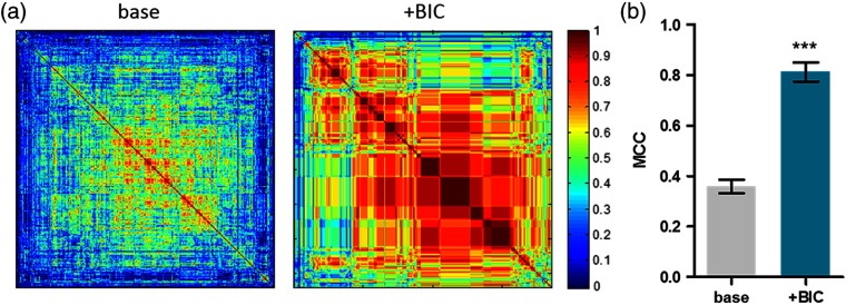
The spike train data of neurons sorted by our method were also useful to analyze the synchronous activity of neural networks. We calculated the pairwise cross-correlation between two cellular trains and applied the hierarchical clustering method to show the synchrony level with respect to the chemical perturbation. The presence of more reddish colors in the correlation matrix after the bicuculline treatment than that of before (“base”) implied that the more cells simultaneously fired [Fig. 7(a)]. Quantitatively, the mean correlation coefficient after bicuculline treatment was significantly higher than that of the before (“base”), also supporting that bicuculline-induced network synchronization [Fig. 7(b)]. Altogether, our results demonstrated that our spike train-based approach to the calcium imaging data analysis allowed quantification of individual neural activities and network synchrony for stimulus-response experiments with five distinct measures.
Fig. 7.
The effect of the bicuculline treatment on network synchronization. (a) In the case of the bicuculline treatment, the cross-correlation analysis between before (base) and after treatment (+BIC) was performed to investigate the network synchronization effect. (b) Mean correlation coefficients (MCC) of each case were used as a quantitative measure (; FOVs; ; ns: not significant).
3.6. Post Analysis 2: Spatiotemporal Mapping of Neuronal Firing Patterns in Synchronous Network Bursts
To demonstrate the applicability of our toolbox to synchronous events in neural networks, we attempted to analyze the firing patterns of neurons in bursting networks. To detect each network burst from the spike train data [Fig. 8(a), (i)], we counted the number of firing cells at each frame of an image sequence [Fig. 8(a), (ii)] and divided it into the total number of cells to construct the ratio profile of firing cells over time [Fig. 8(a), (iii)]. By thresholding this profile, we detected peaks above the threshold as the burst point. Furthermore, the start and end points of each burst were defined as the time point at which all neurons were silent before and after the burst point. Using the real data from cultured networks, we detected the timing of network bursts and extracted all the spikes involved with each burst [Figs. 8(b) and 8(b’)]. Under our definition, we observed that all neurons were silent before and after the burst point, respectively (, bursts in 11 networks). The mean duration and inter-burst interval of network bursts was (, bursts in 11 networks) and (, bursts in 11 networks), respectively, and comparable to the results using the cultured networks at the similar ages with multichannel electrophysiological tools.45,46
Fig. 8.
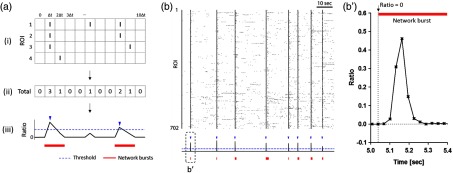
Synchronous network burst detection from calcium spike trains. (a) The procedure for network burst detection. From the raster plot of the entire ROIs (i), we calculated the number of activate ROIs at each frame (ii) and obtained a network burst profile by normalizing each value to the total number of ROI (iii). The peaks of the profiles above the threshold (blue dashed line) were detected as the point of network bursts (indicated by blue arrowheads). The duration of each network burst was defined as the period between the frames when all ROIs were silent (indicated by red bold lines). (b) The representative examples of the real raster plot (top) obtained from Fig. 5 and the network burst profile (bottom). The points of network bursts and their durations were marked by blue arrowheads and red bold lines, respectively. (b’) The magnified version of the ratio graph in the bottom of (b), showing the start point at which all neurons were silent before the burst point.
The location of neurons and their spikes participating in one network burst were then utilized to map the propagation of synchronous activity. As exemplified in Fig. 9, we could categorize the spikes in a single burst according to their timestamp. Figure 9(a) shows the difference in the onset timing of seven groups, indicating the capability of our spike detection method to resolve neuronal firing within a single burst. It should be noted that our data were collected with a frame rate of 30 Hz, which is much slower than the previous work for similar analysis.8 This shows that our frame rate was sufficient to segregate neurons into several groups based on their firing, and signal propagation map of a single burst could be visualized (“Pseudocolored map” in Fig. 9).
Fig. 9.
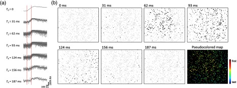
Spatiotemporal mapping of signal propagation within a network burst. (a) The kinetics of calcium spikes in each group (categorized according to the timing of detected spikes). The spikes of each cell were marked as gray curves, and the average spike in each group was marked as a black curve. Two red dashed lines indicate the onset timing of calcium spikes in the first and last group. (b) Black dots indicate the neurons fired at each time point and gray dots silent ones. These time-series images were then merged into one by color-coding (“Pseudocolored map”); in this image, early firing neurons were marked as red colors and late firing neurons as blue colors.
By collecting all the firing patterns of each network burst, we quantitatively analyzed the similarity of the sequences. As the patterns of signal propagation were described as a sequence of neuronal groups in our analysis, we used Kendal’s to adjust the tied ranks of cells in the same group. The pairwise comparison using Kendal’s statistics and hierarchical clustering of the correlation matrix revealed the similar sequences of neuronal firing emerged from different network bursts [Fig. 10(a)]. Prior to the clustering of the matrix, there was no apparent region that shared similar activity patterns, indicating that several patterns alternatively appeared rather than locally repeated [Fig. 10(b)]. To quantitatively evaluate the nonrandomness of firing patterns, we separately shuffled the order of ROIs in each burst and compared the renewed correlation matrix to the original one. As a result, the mean coefficient () of the real data was significantly higher than that of the shuffled one, which was close to 0. The results implied that despite the entire regeneration of cellular connections in dissociated cultures, several consistent patterns of neuronal firing alternatively repeated in spontaneous, synchronous events.
Fig. 10.
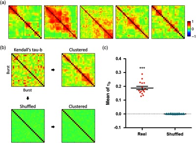
Consistent sequence of neuronal firing repeated appeared in network bursts. (a) Representative correlation matrix based on Kendall’s in five different networks. All matrices were sorted according to a hierarchical clustering. (b) Pairwise calculation of Kendall’s between all firing orders of each burst (top, left) was clustered to find consistent sequences (top, right). To statistically confirm the nonrandomness of firing patterns, the firing order of each burst was shuffled (bottom, left) and the correlation matrix was clustered as same as the original one (bottom, right). (c) When the coefficients of all possible pairs were averaged, the real data revealed much higher values than shuffled [; (“Real”) and 75 (“Shuffled”); under paired test].
4. Discussion
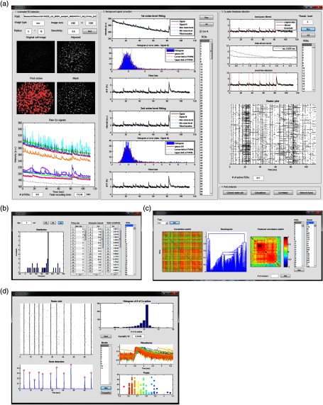
Here, we introduced NeuroCa, a toolbox that includes a series of algorithms for the automated analysis of calcium imaging data from large-scale neural networks (Fig. 11 shows the graphical user-interfaces modularized for data processing and post analysis). Our cell identification algorithm was efficient to detect cell bodies regardless of cell types or activity levels and was notably useful in separating individual ones that are very close to each other. We also devised computational strategies for adjusting the baseline level of fluorescence signals and estimating the spike waveform from the real data, which facilitated the successful detection of small transients. Using this method, we were able to construct individual spike trains of cells in a submillimeter-sized network. Our method combined the advantage of optical recording and spike train analysis, allowing us to not only easily extract the quantitative measures of neural activity but also to perform the spatiotemporal mapping of cellular firing in a population activity, especially synchronous bursts.
Fig. 11.
Moreover, identifying cell bodies using a morphological filter in NeuroCa allows not only detecting most of the cells in a FOV with high accuracy, but also distinguishing individual ones from clustered regions. Essentially, CHT determines a circular object based on the intensity of local pixels, therefore being less sensitive to the imbalance background illumination than other image segmentation algorithms.22,25,27,34 In addition, much higher spatial resolution was achieved in our method; for example, our CHT-based method showed less than 5% of the error rate (the percentage of ROIs that contained multiple cells), which was two times less than the previous algorithm based on watershed transform (11%).42 The minimum cell-to-cell distance that our algorithm could separate was about (center-to-center distance). Considered the diameter of cells as , this feature implies the possibility of our method for isolating cells even if they are partially overlapped each other. Consequently, our method will be also applicable to the analysis of larger and denser neuronal population including tissue slices or a three-dimensional brain, where cells were far closer than dissociated cultures.
Adapting the deconvolution method with an additional step for baseline adjustment and template estimation from the real data, we were able to detect calcium spikes as small as one reflecting a single action potential firing with high accuracy. As some calcium imaging and modeling studies suggested the exponential form of calcium spikes in response to the action potentials,38,47,48 it was reasonable to infer the timing of action potential firing by deconvolving the original fluorescent signal with an exponential kernel.17,24,30,35,49 The performance of this method critically relied on how flat the baseline of the signal was and how accurate the estimated exponential model was for each neuron. However, most practical cases include the photobleaching decay of fluorescent indicators in calcium signals, and the waveform of calcium spikes varied in different cells. Here, we exploited curve fitting in order to estimate a background trend and spike waveform for each cellular signals, thereby compensating for cell variance. This capability of our method will facilitate data analysis obtained from various neural networks regardless of cellular types or their temporal firing patterns.
Our analysis of calcium imaging data recorded from a large cultured network demonstrates the utility of NeuroCa to scrutinize the spatial and temporal patterns of neuronal activity with various quantitative measures. In the chemical perturbation study, the alteration of neural activity and synchrony was faithfully represented by five measures including MFR, ISI, calcium spike amplitude, the percentage of active cells, and pairwise cross-correlation.11,13,33 Furthermore, with the advantage of optical recording that provides the spatial information of individual cells, it was also possible to map the rapid propagation of neural activity during the short duration of synchronous events. Several previous methods were suggested to identify the coherent activity from calcium signals and provide the spatial organization of cellular assemblies,34,50 but it is still difficult to uncover the temporal sequences of cellular firing within such short period events. Our results using NeuroCa, on the other hand, showed the spatial location of cells as well as their temporal orders, allowing us to obtain insights that are pertinent to hidden signaling pathways mediating the synchronous activity.
Our studies demonstrate that cultured neural networks revealed several consistent patterns of neuronal activity in synchronous bursting events despite the overall regeneration of cellular connectivity. In slice cultures that are composed of intact neural circuits of neurons, the sequence of cellular activation was reliably repeated in synchronous activity,8 and several types of patterns emerged from one network over time.1 Such repetition and diversity of consistent firing patterns have implied their role in serving as the substrate for information processing and storage.1 However, in dissociated cultures, although such a tendency of repeated patterns across the subregions of a large network has been reported in several studies using microelectrode arrays,51–53 the contribution of each cell to the activity patterns of synchrony remains unknown. Our results support these previous results and also extend the existence of sequential activation at the cellular level.
NeuroCa is essentially applicable to other types of data using different indicators (genetic5,14 or voltage-sensitive dyes54) or imaging tools (two-photon55 or light sheet microscopic imaging11,13,17). In addition, data from tissue slices or living animals were also available to be analyzed. However, for further applications, several additional algorithms will be necessary. First, NeuroCa has a limitation in detecting other neuronal areas such as dendrites24,33,56 or neurophils,57 which have been also of interest for investigating cellular signaling or intercellular interaction in localized regions. We anticipate that it could be resolved by combining additional morphological filters. Second, a sophisticated algorithm for separating cell types, such as neurons and glial cells, will be necessary. Third, movement correction and 3D-optimized cell identification will be required, especially for the data from living animals.24
NeuroCa will provide the opportunities to come close to the answer to some interesting questions in neuroscience: how individual neurons functionally participate in the various modes of brain activity and what is the role of functional interactions between neurons and glial cells in circuit dynamics? One possibility for such studies is to apply our method to in vivo systems. Recently, optical recording technologies have been exploited to the various types of living animals, such as C. elegans,13 zebrafish,11,12 rodents,16,19,48,58 or primates.59 These studies have reported the impressive results of neural activity at population level and also suggested the great promise of optical neural recording technologies in functional mapping of the brain. In this stream of neuroscience research, a convenient and user-friendly tool, such as our NeuroCa, is certainly necessary for the analysis of large-scale neural data. We believe that our tool will contribute to innovative studies such as the BRAIN initiative,60 considerably reducing the enormous loads of postexperimentation steps. NeuroCa is available for free public download (see Ref. 61).
5. Conclusions
We present a new computational approach for the automated analysis of calcium imaging data from a large neural network. Our methods facilitated the identification of individual cells from an image sequence and the detection of spikes from neuronal calcium signals. The calcium spike trains were useful to quantitatively analyze the overall activity of neuronal population. Furthermore, our method enabled us to map the spatiotemporal patterns of cellular firing in a large network when they synchronously fired. We believe that our approach will be a powerful tool that can contribute to the functional mapping of the brain.
Acknowledgments
This work was supported by the National Research Foundation of Korea (NRF) funded by the Korean Government (MSIP) (NRF-2015R1A2A1A09003605, NRF-2012R1A2A1A01007327, and NRF-2011-0007476).
Biographies
Min Jee Jang is a postdoctoral fellow at Korea University. She received her BS, MS, and PhD degrees in bio and brain engineering from the Korea Advanced Institute of Science and Technology (KAIST) in 2009, 2011, and 2015, respectively. She is an author in seven journal papers, five of them as the first author. Her current research interests include neural circuit patterning, optical neurophysiology, and neural network analysis.
Yoonkey Nam is an associate professor at KAIST, Daejeon, Korea. He received his BS degree from Seoul National University, Seoul, Korea, in 1997 and his MS and PhD degrees in electrical engineering from the University of Illinois at Urbana–Champaign, Urbana, Illinois, United States, in 2003 and 2005, respectively. Since 2006, he has been with KAIST, where he is now an associate professor of bio and brain engineering. His current research interests include micro- and nanotechnology in neuroscience, multichannel neural signal processing, optical recording, and stimulation of nerve tissues.
References
- 1.Beggs J. M., Plenz D., “Neuronal avalanches are diverse and precise activity patterns that are stable for many hours in cortical slice cultures,” J. Neurosci. 24(22), 5216–5229 (2004). 10.1523/JNEUROSCI.0540-04.2004 [DOI] [PMC free article] [PubMed] [Google Scholar]
- 2.Ikegaya Y., et al. , “Synfire chains and cortical songs: temporal modules of cortical activity,” Science 304(5670), 559–564 (2004). 10.1126/science.1093173 [DOI] [PubMed] [Google Scholar]
- 3.Buzsáki G., Draguhn A., “Neuronal oscillations in cortical networks,” Science 304(5679), 1926–1929 (2004). 10.1126/science.1099745 [DOI] [PubMed] [Google Scholar]
- 4.Göbel W., Helmchen F., “In vivo calcium imaging of neural network function,” Physiology 22, 358–365 (2007). 10.1152/physiol.00032.2007 [DOI] [PubMed] [Google Scholar]
- 5.Grienberger C., Konnerth A., “Imaging calcium in neurons,” Neuron 73(5), 862–885 (2012). 10.1016/j.neuron.2012.02.011 [DOI] [PubMed] [Google Scholar]
- 6.Orlandi J. G., et al. , “Noise focusing and the emergence of coherent activity in neuronal cultures,” Nat. Phys. 9, 582–890 (2013). 10.1038/nphys2686 [DOI] [Google Scholar]
- 7.Soriano J., et al. , “Development of input connections in neural cultures,” Proc. Natl. Acad. Sci. U. S. A. 105(37), 13758–13763 (2008). 10.1073/pnas.0707492105 [DOI] [PMC free article] [PubMed] [Google Scholar]
- 8.Takano H., et al. , “Deterministic and stochastic neuronal contributions to distinct synchronous CA3 network bursts,” J. Neurosci. 32(14), 4743–4754 (2012). 10.1523/JNEUROSCI.4277-11.2012 [DOI] [PMC free article] [PubMed] [Google Scholar]
- 9.Allène C., et al. , “Dynamic changes in interneuron morphophysiological properties mark the maturation of hippocampal network activity,” J. Neurosci. 32(19), 6688–6698 (2012). 10.1523/JNEUROSCI.0081-12.2012 [DOI] [PMC free article] [PubMed] [Google Scholar]
- 10.Crépel V., et al. , “A parturition-associated nonsynaptic coherent activity pattern in the developing hippocampus,” Neuron 54(1), 105–120 (2007). 10.1016/j.neuron.2007.03.007 [DOI] [PubMed] [Google Scholar]
- 11.Ahrens M. B., et al. , “Whole-brain functional imaging at cellular resolution using light-sheet microscopy,” Nat. Methods 10(5), 413–420 (2013). 10.1038/nmeth.2434 [DOI] [PubMed] [Google Scholar]
- 12.Ahrens M. B., et al. , “Brain-wide neuronal dynamics during motor adaptation in zebrafish,” Nature 485(7399), 471–477 (2012). 10.1038/nature11057 [DOI] [PMC free article] [PubMed] [Google Scholar]
- 13.Schrödel T., et al. , “Brain-wide 3D imaging of neuronal activity in Caenorhabditis elegans with sculpted light,” Nat. Methods 10(10), 1013–1020 (2013). 10.1038/nmeth.2637 [DOI] [PubMed] [Google Scholar]
- 14.Knöpfel T., “Genetically encoded optical indicators for the analysis of neuronal circuits,” Nat. Rev. Neurosci. 13(10), 687–700 (2012). 10.1038/nrn3293 [DOI] [PubMed] [Google Scholar]
- 15.Cao G., et al. , “Genetically targeted optical electrophysiology in intact neural circuits,” Cell 154(4), 904–913 (2013). 10.1016/j.cell.2013.07.027 [DOI] [PMC free article] [PubMed] [Google Scholar]
- 16.Chen J. L., et al. , “Imaging neuronal populations in behaving rodents: paradigms for studying neural circuits underlying behavior in the mammalian cortex,” J. Neurosci. 33(45), 17631–17640 (2013). 10.1523/JNEUROSCI.3255-13.2013 [DOI] [PMC free article] [PubMed] [Google Scholar]
- 17.Holekamp T. F., Turaga D., Holy T. E., “Fast three-dimensional fluorescence imaging of activity in neural populations by objective-coupled planar illumination microscopy,” Neuron 57(5), 661–672 (2008). 10.1016/j.neuron.2008.01.011 [DOI] [PubMed] [Google Scholar]
- 18.Osten P., Margrie T. W., “Mapping brain circuitry with a light microscope,” Nat. Methods 10(6), 515–523 (2013). 10.1038/nmeth.2477 [DOI] [PMC free article] [PubMed] [Google Scholar]
- 19.Sato T. R., et al. , “The functional microarchitecture of the mouse barrel cortex,” PLoS Biol. 5(7), e189 (2007). 10.1371/journal.pbio.0050189 [DOI] [PMC free article] [PubMed] [Google Scholar]
- 20.Greenberg D. S., Houweling A. R., Kerr J. N. D., “Population imaging of ongoing neuronal activity in the visual cortex of awake rats,” Nat. Neurosci. 11(7), 749–751 (2008). 10.1038/nn.2140 [DOI] [PubMed] [Google Scholar]
- 21.Takahashi N., et al. , “Circuit topology for synchronizing neurons in spontaneously active networks,” Proc. Natl. Acad. Sci. U. S. A 107(22), 10244–10249 (2010). 10.1073/pnas.0914594107 [DOI] [PMC free article] [PubMed] [Google Scholar]
- 22.Dorostkar M. M., et al. , “Computational processing of optical measurements of neuronal and synaptic activity in networks,” J. Neurosci. Methods 188(1), 141–150 (2010). 10.1016/j.jneumeth.2010.01.033 [DOI] [PMC free article] [PubMed] [Google Scholar]
- 23.Ohki K., et al. , “Functional imaging with cellular resolution reveals precise micro-architecture in visual cortex,” Nature 433(7026), 597–603 (2005). 10.1038/nature03274 [DOI] [PubMed] [Google Scholar]
- 24.Mukamel E. A., Nimmerjahn A., Schnitzer M. J., “Automated analysis of cellular signals from large-scale calcium imaging data,” Neuron 63(6), 747–760 (2009). 10.1016/j.neuron.2009.08.009 [DOI] [PMC free article] [PubMed] [Google Scholar]
- 25.Valmianski I., et al. , “Automatic identification of fluorescently labeled brain cells for rapid functional imaging,” J. Neurophysiol. 104(3), 1803–1811 (2010). 10.1152/jn.00484.2010 [DOI] [PMC free article] [PubMed] [Google Scholar]
- 26.Maruyama R., et al. , “Detecting cells using non-negative matrix factorization on calcium imaging data,” Neural Network. 55, 11–19 (2014). 10.1016/j.neunet.2014.03.007 [DOI] [PubMed] [Google Scholar]
- 27.Wong L. C., et al. , “Fully-automated image processing software to analyze calcium traces in populations of single cells,” Cell Calcium 48(5), 270–274 (2010). 10.1016/j.ceca.2010.09.008 [DOI] [PubMed] [Google Scholar]
- 28.Oñativia J., Schultz S. R., Dragotti P. L., “A finite rate of innovation algorithm for fast and accurate spike detection from two-photon calcium imaging,” J. Neural. Eng. 10(4), 046017 (2013). 10.1088/1741-2560/10/4/046017 [DOI] [PMC free article] [PubMed] [Google Scholar]
- 29.Sasaki T., et al. , “Fast and accurate detection of action potentials from somatic calcium fluctuations,” J. Neurophysiol. 100(3), 1668–1676 (2008). 10.1152/jn.00084.2008 [DOI] [PubMed] [Google Scholar]
- 30.Vogelstein J. T., et al. , “Fast nonnegative deconvolution for spike train inference from population calcium imaging,” J. Neurophysiol. 104(6), 3691–3704 (2010). 10.1152/jn.01073.2009 [DOI] [PMC free article] [PubMed] [Google Scholar]
- 31.Quan T., et al. , “Method to reconstruct neuronal action potential train from two-photon calcium imaging,” J. Biomed. Opt. 15(6), 066002 (2010). 10.1117/1.3505021 [DOI] [PMC free article] [PubMed] [Google Scholar]
- 32.Wilt B. A., Fitzgerald J. E., Schnitzer M. J., “Photon shot noise limits on optical detection of neuronal spikes and estimation of spike timing,” Biophys. J. 104(1), 51–62 (2013). 10.1016/j.bpj.2012.07.058 [DOI] [PMC free article] [PubMed] [Google Scholar]
- 33.Ozden I., et al. , “Identification and clustering of event patterns from in vivo multiphoton optical recordings of neuronal ensembles,” J. Neurophysiol. 100(1), 495–503 (2008). 10.1152/jn.01310.2007 [DOI] [PMC free article] [PubMed] [Google Scholar]
- 34.Reichinnek S., et al. , “Reliable optical detection of coherent neuronal activity in fast oscillating networks in vitro,” NeuroImage 60(1), 139–152 (2012). 10.1016/j.neuroimage.2011.12.018 [DOI] [PubMed] [Google Scholar]
- 35.Yaksi E., Friedrich R. W., “Reconstruction of firing rate changes across neuronal populations by temporally deconvolved imaging,” Nat. Methods 3(5), 377–383 (2006). 10.1038/nmeth874 [DOI] [PubMed] [Google Scholar]
- 36.Yuen H. K., et al. , “Comparative study of Hough transform methods for circle finding,” Image Vision Comput. 8(1), 71–77 (1990). 10.1016/0262-8856(90)90059-E [DOI] [Google Scholar]
- 37.Dichter M. A., “Rat cortical neurons in cell culture: culture methods, cell morphology, electrophysiology, and synapse formation,” Brain Res. 149(2), 279–293 (1978). 10.1016/0006-8993(78)90476-6 [DOI] [PubMed] [Google Scholar]
- 38.Helmchen F., Imoto K., Sakmann B., “ buffering and action potential-evoked signaling in dendrites of pyramidal neurons,” Biophys. J. 70(2), 1069–1081 (1996). 10.1016/S0006-3495(96)79653-4 [DOI] [PMC free article] [PubMed] [Google Scholar]
- 39.Smetters D., Majewska A., Yuste R., “Detecting action potentials in neuronal populations with calcium imaging,” Methods 18(2), 215–221 (1999). 10.1006/meth.1999.0774 [DOI] [PubMed] [Google Scholar]
- 40.Thompson L. T., Best P. J., “Place cells and silent cells in the hippocampus of freely-behaving rats,” J. Neurosci. 9(7), 2382–2390 (1989). [DOI] [PMC free article] [PubMed] [Google Scholar]
- 41.Gambino F., et al. , “Sensory-evoked LTP driven by dendritic plateau potentials in vivo,” Nature 515(7525), 116–119 (2014). 10.1038/nature13664 [DOI] [PubMed] [Google Scholar]
- 42.Frega M., et al. , “Cortical cultures coupled to micro-electrode arrays: a novel approach to perform in vitro excitotoxicity testing,” Neurotoxicol. Teratol. 34(1), 116–127 (2012). 10.1016/j.ntt.2011.08.001 [DOI] [PubMed] [Google Scholar]
- 43.Gullo F., et al. , “Orchestration of ‘presto’ and ‘largo’ synchrony in up-down activity of cortical networks,” Front Neural Circuits 4, 11 (2010). 10.3389/fncir.2010.00011 [DOI] [PMC free article] [PubMed] [Google Scholar]
- 44.Le Magueresse C., et al. , “Nicotinic modulation of network and synaptic transmission in the immature hippocampus investigated with genetically modified mice,” J. Physiol. 576(2), 533–546 (2006). 10.1113/jphysiol.2006.117572 [DOI] [PMC free article] [PubMed] [Google Scholar]
- 45.Chiappalone M., et al. , “Burst detection algorithms for the analysis of spatio-temporal patterns in cortical networks of neurons,” Neurocomputing 65-66, 653–662 (2005). 10.1016/j.neucom.2004.10.094 [DOI] [Google Scholar]
- 46.Chiappalone M., et al. , “Dissociated cortical networks show spontaneously correlated activity patterns during in vitro development,” Brain Res. 1093(1), 41–53 (2006). 10.1016/j.brainres.2006.03.049 [DOI] [PubMed] [Google Scholar]
- 47.Helmchen F., Borst J., Sakmann B., “Calcium dynamics associated with a single action potential in a CNS presynaptic terminal,” Biophys. J. 72(3), 1458–1471 (1997). 10.1016/S0006-3495(97)78792-7 [DOI] [PMC free article] [PubMed] [Google Scholar]
- 48.Rothschild G., Nelken I., Mizrahi A., “Functional organization and population dynamics in the mouse primary auditory cortex,” Nat. Neurosci. 13(3), 353–360 (2010). 10.1038/nn.2484 [DOI] [PubMed] [Google Scholar]
- 49.Park I. J., et al. , “Quantifying bursting neuron activity from calcium signals using blind deconvolution,” J. Neurosci. Methods 218(2), 196–205 (2013). 10.1016/j.jneumeth.2013.05.007 [DOI] [PMC free article] [PubMed] [Google Scholar]
- 50.Feldt S., Soltesz I., Cossart R., “Spatially clustered neuronal assemblies comprise the microstructure of synchrony in chronically epileptic networks,” Proc. Natl. Acad. Sci. U. S. A 110(9), 3567–3572 (2013). 10.1073/pnas.1216958110 [DOI] [PMC free article] [PubMed] [Google Scholar]
- 51.Eytan D., Marom S., “Dynamics and effective topology underlying synchronization in networks of cortical neurons,” J. Neurosci. 26(33), 8465–8476 (2006). 10.1523/JNEUROSCI.1627-06.2006 [DOI] [PMC free article] [PubMed] [Google Scholar]
- 52.Raichman N., Ben-Jacob E., “Identifying repeating motifs in the activation of synchronized bursts in cultured neuronal networks,” J. Neurosci. Methods 170(1), 96–110 (2008). 10.1016/j.jneumeth.2007.12.020 [DOI] [PubMed] [Google Scholar]
- 53.Rolston J. D., Wagenaar D. A., Potter S. M., “Precisely timed spatiotemporal patterns of neural activity in dissociated cortical cultures,” Neuroscience 148(1), 294–303 (2007). 10.1016/j.neuroscience.2007.05.025 [DOI] [PMC free article] [PubMed] [Google Scholar]
- 54.Peterka D. S., Takahashi H., Yuste R., “Imaging voltage in neurons,” Neuron 69(1), 9–21 (2011). 10.1016/j.neuron.2010.12.010 [DOI] [PMC free article] [PubMed] [Google Scholar]
- 55.Grewe B. F., et al. , “High-speed in vivo calcium imaging reveals neuronal network activity with near-millisecond precision,” Nat. Methods 7(5), 399–405 (2010). 10.1038/nmeth.1453 [DOI] [PubMed] [Google Scholar]
- 56.Kleindienst T., et al. , “Activity-dependent clustering of functional synaptic inputs on developing hippocampal dendrites,” Neuron 72(6), 1012–1024 (2011). 10.1016/j.neuron.2011.10.015 [DOI] [PubMed] [Google Scholar]
- 57.Wallace D. J., et al. , “Single-spike detection in vitro and in vivo with a genetic sensor,” Nat. Methods 5(9), 797–804 (2008). 10.1038/nmeth.1242 [DOI] [PubMed] [Google Scholar]
- 58.Berger T., et al. , “Combined voltage and calcium epifluorescence imaging in vitro and in vivo reveals subthreshold and suprathreshold dynamics of mouse barrel cortex,” J. Neurophysiol. 97(5), 3751–3762 (2007). 10.1152/jn.01178.2006 [DOI] [PubMed] [Google Scholar]
- 59.Heider B., et al. , “Two-photon imaging of calcium in virally transfected striate cortical neurons of behaving monkey,” PLoS One 5(11), e13829 (2010). 10.1371/journal.pone.0013829 [DOI] [PMC free article] [PubMed] [Google Scholar]
- 60.Insel T. R., Landis S. C., Collins F. S., “The NIH BRAIN initiative,” Science 340(6133), 687–688 (2013). 10.1126/science.1239276 [DOI] [PMC free article] [PubMed] [Google Scholar]
- 61. http://neuros.kaist.ac.kr/neuroca
Associated Data
This section collects any data citations, data availability statements, or supplementary materials included in this article.


