Significance
A long-standing challenge in material design is to overcome the conflict between strength and toughness, because they are generally mutually exclusive. To address this challenge, we rationally design cellulose-based nanopaper and investigate the dependence of their mechanical properties on constituent cellulose fiber size. Surprisingly, we find that both the strength and toughness of the nanopaper increase simultaneously (40 and 130 times, respectively) as the average diameter of constituent cellulose fibers decreases from 27 μm to 11 nm, suggesting the promising potential toward an anomalous but highly desirable scaling law: the smaller, the stronger and the tougher. There are abundant opportunities to use the fundamental bottom-up strategy to design a novel class of functional materials that are both strong and tough.
Keywords: strength, toughness, scaling law, cellulose, hydrogen bond
Abstract
The quest for both strength and toughness is perpetual in advanced material design; unfortunately, these two mechanical properties are generally mutually exclusive. So far there exists only limited success of attaining both strength and toughness, which often needs material-specific, complicated, or expensive synthesis processes and thus can hardly be applicable to other materials. A general mechanism to address the conflict between strength and toughness still remains elusive. Here we report a first-of-its-kind study of the dependence of strength and toughness of cellulose nanopaper on the size of the constituent cellulose fibers. Surprisingly, we find that both the strength and toughness of cellulose nanopaper increase simultaneously (40 and 130 times, respectively) as the size of the constituent cellulose fibers decreases (from a mean diameter of 27 μm to 11 nm), revealing an anomalous but highly desirable scaling law of the mechanical properties of cellulose nanopaper: the smaller, the stronger and the tougher. Further fundamental mechanistic studies reveal that reduced intrinsic defect size and facile (re)formation of strong hydrogen bonding among cellulose molecular chains is the underlying key to this new scaling law of mechanical properties. These mechanistic findings are generally applicable to other material building blocks, and therefore open up abundant opportunities to use the fundamental bottom-up strategy to design a new class of functional materials that are both strong and tough.
The need for engineering materials that are both strong and tough is ubiquitous. However, the design of strong and tough materials is often inevitably a compromise as these two properties generally contradict each other (1). Toughness requires a material’s ability of dissipating local high stress by enduring deformation. Consequently, hard materials tend to be brittle (less tough); lower-strength materials, which can deform more readily, tend to be tougher (2, 3). For example, the toughness of metals and alloys is usually inversely proportional to their strength (4). Acknowledging such a necessary compromise, one would expect that research on advanced material design would be focused on achieving an optimum combination of these two properties. Indeed much research effort is focused on pursuing higher strength, with rather limited corresponding regard for toughness (5–10). One example is the enthusiasm sparked by the discovery of carbon nanotubes (CNTs), which exhibit remarkably high strength. However, it still remains uncertain how such a strong material can be incorporated with bulk materials to benefit from its high strength without sacrificing toughness.
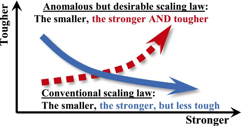
There have been tremendous efforts recently to develop materials with higher strength using smaller material structures. For example, by decreasing the grain size of metals, dislocation motions (thus plasticity) are more restricted, leading to a higher strength (5–10). However, such treatments also minimize possible mechanisms (e.g., crack-tip blunting) to relieve local high stress, resulting in lower toughness. The atomic scale origins of high strength of a material, e.g., strong directional bonding and limited dislocation mobility, are also essentially the roots for brittleness of the material. In short, the well-recognized scaling law of “the smaller, the stronger” comes at a price of sacrificing toughness (Fig. 1).
Fig. 1.
An anomalous but desirable scaling law of mechanical properties requires defeating the conventional conflict between strength and toughness.
The prevailing toughening mechanisms can be categorized into two types: intrinsic and extrinsic. Intrinsic toughening operates ahead of a crack tip to suppress its propagation; it is primarily related to plasticity, and thus the primary source of fracture toughness in ductile materials. Recent progress involves introducing high-density nanotwin boundaries in metals to achieve high strength and toughness (11–15). Intrinsic toughening mechanisms are essentially ineffective with brittle materials, e.g., ceramics, which invariably must rely on extrinsic toughening (2). Extrinsic toughening acts mainly behind the crack tip to effectively reduce the crack-driving force by microstructural mechanisms, e.g., crack bridging and meandering and crack surface sliding (16–18). A counterintuitive but successful example is the development of bulk metallic glass (BMG)-based composites, in which a crystalline dendrite second phase is introduced into the BMG matrix to promote the formation of multiple shear bands, leading to a strong and also tough material (3, 9, 16, 19–21). Intrinsic and extrinsic toughening mechanisms are also found to be effective in natural materials (e.g., bones and nacres), which often involve the hierarchical structure and/or a “brick-and-mortar” hybrid microstructure of the material (22–26). Nature-inspired toughening mechanisms are also used to synthesize biomimetic structural materials. Nonetheless, so far, there exists only rather limited success in attaining both strength and toughness, which often involve material-specific, complicated (e.g., growing high density nanotwins), or expensive (e.g., BMG-dendrite composites) synthesis processes and thus are hardly applicable to other materials. A general and feasible mechanism to address the conflict between strength and toughness still remains elusive.
Aiming to shed insight on the long-sought strategy addressing the conflict between strength and toughness, we rationally design cellulose-based nanopaper and investigate the dependence of their mechanical properties on constituent cellulose fiber size. Surprisingly, we find that both the strength and toughness of the nanopaper increase simultaneously (40 and 130 times, respectively) as the size of the constituent cellulose building blocks decreases (from a mean diameter of 27 µm to 11 nm). These stimulating results suggest the promising potential toward a new and highly desirable scaling law: the smaller, the stronger and the tougher (Fig. 1). Though the increasing strength as the diameter of cellulose fiber decreases can be attributed to reduced intrinsic defect size, and the dependence is well captured by a continuum fracture mechanics model, our atomistic simulations reveal that facile formation and reformation of strong hydrogen bonding among cellulose chains is the key to the simultaneously increasing toughness. These mechanistic findings that underpin the highly desirable scaling law of mechanical properties suggest a fundamental bottom-up material design strategy generally applicable to other material building blocks as well, and therefore open up abundant opportunities toward a novel class of engineering materials that are both strong and tough.
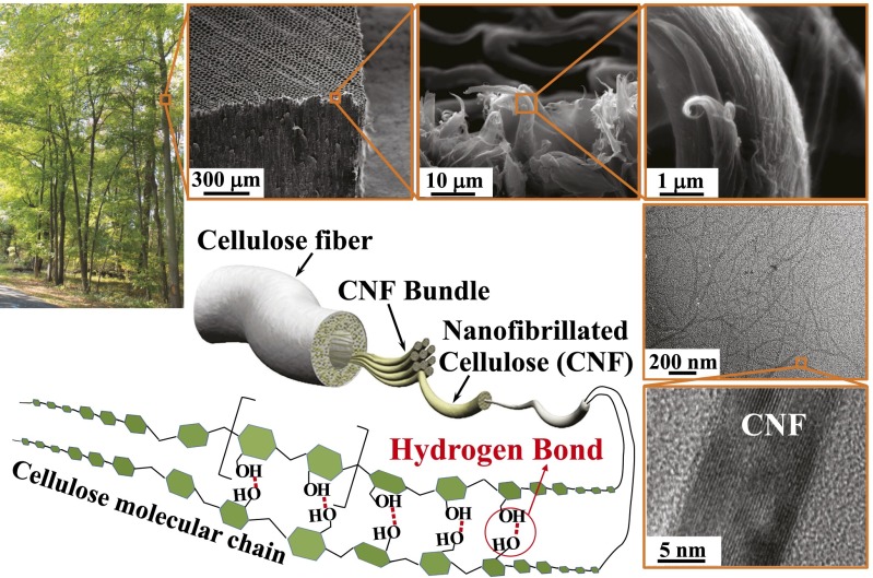
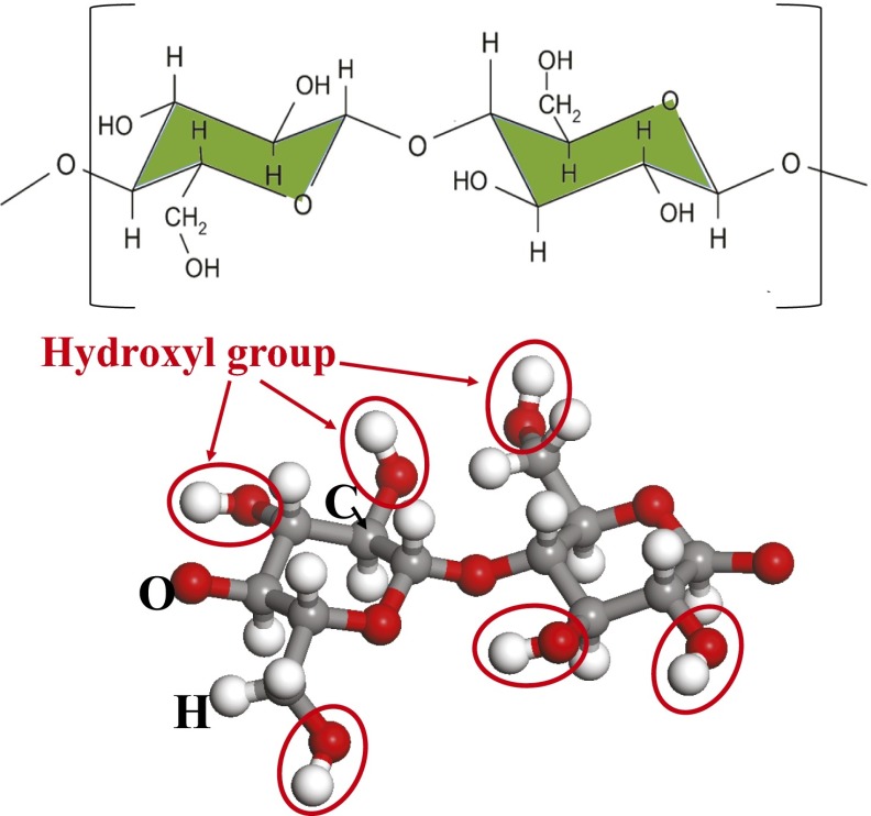
Cellulose is the most abundant biopolymer on Earth and has long been used as the sustainable building block for conventional paper. Cellulose has appealing mechanical properties, with specific modulus [∼100 GPa/(g/cm3)] and specific strength [∼4 GPa/(g/cm3)] higher than most metals and composites, and many ceramics, making it as a promising building block for functional and structural materials (27). Wood fibers are the main natural source of cellulose and have an intrinsically hierarchical structure (Fig. 2). A 20- to ∼50-µm-thick native wood fiber comprises thousands of nanofibrillated cellulose (CNF) fibers (5–50 nm in diameter), each of which can be disintegrated into finer elementary fibrils consisting of cellulose molecular chains (27–36). Cellulose molecule is a linear chain of ringed glucose molecules, with a repeat unit (Fig. S1) comprising two anhydroglucose rings (C6H10O5) linked through C–O–C covalent bond. Rich hydroxyl groups in cellulose molecule (six in each repeat unit) enable facile formation of hydrogen bonds, both intrachain and interchain (Fig. 2). Whereas the intrachain hydrogen bonding stabilizes the linkage and results in the linear configuration of the cellulose chain, interchain hydrogen bonding among neighboring cellulose molecules plays a pivotal role in the deformation and failure behaviors of cellulose-based materials.
Fig. 2.
Hierarchical structure of wood fibers and the characteristic of cellulose fibrils. Note the rich interchain hydrogen bonds among neighboring cellulose molecular chains.
Fig. S1.
Atomic structure of a cellulose chain repeat unit. Note the six hydroxyl groups (red circles) in each repeat unit.
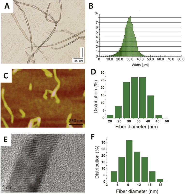
In this study, cellulose fibers of different mean diameters [27 μm (native fiber), 28 nm, and 11 nm, respectively] are isolated from wood cell walls using a top-down approach and characterized (SI Text and Figs. S2 and S3). Cellulose nanopaper is made of a highly entangled random network of CNF fibers (Fig. 3A; Materials and Methods). Regular paper made of 27-μm native cellulose fibers with the same mass per area as the nanopaper is also fabricated as the control. The mechanical properties of both the cellulose nanopaper and regular paper are measured according to ASTM Standard D638 (details in SI Text).
Fig. S2.
(A) Optical microscope image of native cellulose fiber with a mean diameter of 27 μm. (B) Size distribution histogram. (C) AFM image of cellulose fibers with mean diameters of 28 nm. (D) Size distribution histogram. (E) HRTEM crystalline lattice image of fiber with a mean diameter of 11 nm. (F) Size distribution histogram.
Fig. S3.
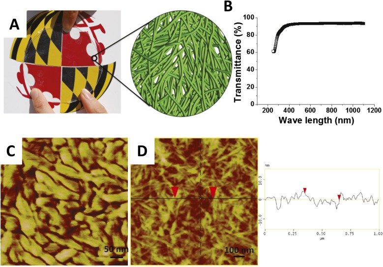
(A) A picture of a transparent cellulose nanopaper (made of CNF fibers of a mean diameter of 11 nm) on the university logo (Left). A schematic of fibrous nanostructure of the nanopaper is also shown (Right). (B) Optical transmittance of transparent cellulose nanopaper in visible and near-infrared range. (C) AFM image of cellulose nanopaper made of CNF fibers of a mean diameter of 28 nm. (D) AFM image and height scan of cellulose nanopaper made of CNF fibers of a mean diameter of 11 nm, showing rms at 1 × 1-μm scan size is 1.5 nm.
Fig. 3.
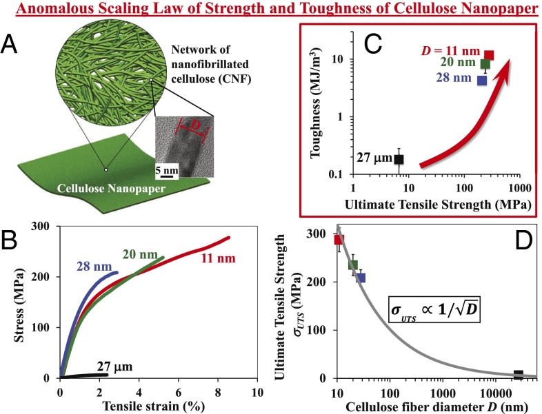
An anomalous scaling law of strength and toughness of cellulose nanopaper. (A) Schematic of cellulose nanopaper, made of a random network of CNF fibers. (Inset) High-resolution transmission electron microscopy (HRTEM) image of an ∼11-nm CNF fiber. (B) Stress–strain curves of cellulose paper made of cellulose fibers of various mean diameters. As the cellulose fiber diameter decreases from micrometer scale to nanometer scale, both tensile strength and ductility of the cellulose paper increases significantly, leading to an anomalous scaling law (C): the smaller, the stronger and the tougher. (D) Reveals that the ultimate tensile strength scales inversely with the square root of cellulose fiber diameter.
Results and Discussions
Fig. 3B shows the typical tensile stress–strain curves of cellulose nanopaper made of fibers of mean diameters of 11 and 28 nm, and that of regular paper made of fibers of mean diameter of 27 μm, respectively. Five samples of each mean fiber diameter are tested and the resulting stress–strain curves are consistent. The stress–strain curve of cellulose nanopaper made of 20 nm fibers in ref. 37 is also plotted in Fig. 3B.
Table 1 lists the mechanical properties of the cellulose nanopaper and regular paper measured from the stress–strain curves: ultimate tensile strength (measured by the maximum stress that the paper can sustain before fracture), toughness (work to fracture, measured by the area under a stress–strain curve), and tensile strain at fracture, for mean fiber diameter of 11 nm, 20 nm, 28 nm, and 27 μm, respectively. The mean value and standard deviation of each property for each mean fiber diameter are calculated from the measurement of five samples.
Table 1.
Mechanical properties for paper made from cellulose fibers with different diameters
| Mean fiber diameter, nm | Tensile strength, MPa | Toughness, MJ/m3 | Fracture strain, % | Density, g/cm3 | Specific strength, MPa/g/cm3 |
| 11 | 275.2 ± 25 | 16.9 ± 1 | 8.5 ± 0.5 | 1.2 | 229.2 ± 21 |
| 20(37) | 235.0 ± 21 | 7.26 ± 2.6 | 5.2 ± 1.2 | ||
| 28 | 208.3 ± 17 | 4.3 ± 0.2 | 2.9 ± 0.1 | 1.2 | 173.6 ± 14 |
| 27,000 | 6.7 ± 0.7 | 0.13 ± 0.1 | 2.4 ± 0.1 | 0.8 | 8.3 ± 0.9 |
Fig. 3C shows the ultimate tensile strength and toughness of the cellulose nanopaper and regular paper for four different mean diameters of cellulose fibers. Surprisingly, as cellulose fiber diameter decreases, both the ultimate tensile strength and toughness of the cellulose paper increase dramatically. As the mean fiber diameter decreases from 27 μm to 11 nm, the ultimate tensile strength increases more than 40 times from 6.7 MPa (regular paper) to 275.2 MPa (11 nm nanopaper); the toughness increases nearly 130 times from 0.13 MJ/m3 (regular paper) to 11.68 MJ/m3 (11-nm nanopaper). Further measurements of the fracture toughness (resistance to crack propagation) of the cellulose paper reveals the similar trend: the fracture toughness increases more than 10 times (from 143.3 to 1,481.4 J/m2) as the mean cellulose fiber diameter decreases from 27 to 11 nm (Figs. S4 and S5). The increased toughness is a result of increased ultimate tensile strength and failure strain with decreasing fiber diameters, as evident in Fig. 3B. In other words, by tuning the constituent fiber diameter, we demonstrate an anomalous scaling law of mechanical properties of cellulose nanopaper: the smaller, the stronger and the tougher. There is no tradeoff between tensile strength and toughness, a highly desirable feature in advanced material design.
Fig. S4.
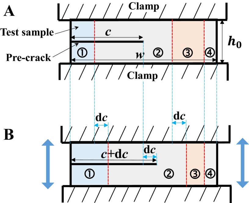
Schematic of the experimental setup to measure the fracture toughness of cellulose paper sample. (A) Clamped test sample with a precrack of length c. (B) Under tension, the precrack propagates to a length of c + dc.
Fig. S5.
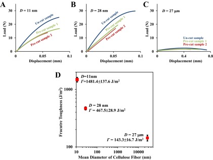
Load displacement curves of cellulose paper samples in fracture toughness test, for various mean diameters of cellulose fiber. (A) 11 nm, (B) 28 nm, and (C) 27 μm. (D) Measured fracture toughness of cellulose paper as a function of mean diameter of the cellulose fibers, which clearly shows a scaling law of the smaller, the tougher.
Fig. 3D shows the tensile strength of cellulose paper as a function of the mean fiber diameter, and clearly depicts the scaling law of the smaller, the stronger, which can be attributed to the reduced intrinsic defect size in constituent cellulose fibers as their diameter decreases, as justified below.
Under tension, the initially entangled random cellulose fiber network deflects and twists to align parallel to the tensile direction. As the tensile load increases, the straightened cellulose fibers begin to fracture, resulting in an overall failure of the paper. This failure mechanism is supported by the SEM observation of the fractured cross section of test samples, showing the CNF fibers are aligned along the tensile loading direction at failure (SI Text). In this sense, the failure stress of an individual cellulose fiber gives a reasonable estimate of the overall tensile strength of nanopaper. A theoretical fracture mechanics model (Fig. S6, details in SI Text) predicts that the ultimate tensile strength of the cellulose nanopaper , with D being the mean fiber diameter. Fig. 3D demonstrates excellent agreement between such a theoretical prediction and experimental measurement (from two independent sources: present study and ref. 37) of the dependence of of cellulose nanopaper and regular paper on constituent fiber diameter over three orders of magnitude, and thus offers strong evidence for the above mechanistic understanding of the scaling law of tensile strength of cellulose nanopaper.
Fig. S6.

Schematics of a cellulose fiber with a preexisting defect under tensile stress . D, fiber diameter; h, size of the flaw.
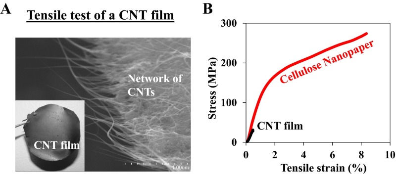
To further shed insight on the anomalous scaling law of strength and toughness of the cellulose nanopaper, we also fabricate single-walled CNT (SWCNT) films with a thickness of 20 μm using the same filtration and drying method as in cellulose nanopaper fabrication. The mean diameter of the constituent SWCNT bundles is 11 nm, comparable to that of the CNF fibers in our strongest and toughest cellulose nanopaper. Tensile test of the SWCNT films is executed under the same conditions as for the cellulose nanopaper. The fractured cross-section of the SWCNT film after the tensile test is examined with SEM (Fig. S7). The initially random network of SWCNTs aligns parallel to the loading direction before fracture, suggesting the similar deformation/failure mechanism as that of the cellulose nanopaper (Fig. S8). By contrast, the comparison of the stress–strain curves of the SWCNT film and cellulose nanopaper reveals significant difference. Despite the exceptional mechanical properties of individual SWCNTs (e.g., with a tensile strength of ∼100 GPa), the SWCNT film yields a tensile strength of 31 MPa, and a toughness of 0.06 MJ/m3, consistent with the data reported in literature (38) but drastically lower (9 times and 195 times, respectively) than those of our cellulose nanopaper made of 11-nm CNF fibers.
Fig. S7.
(A) Optical (Inset) and SEM images of a CNT film made of network of CNTs. (B) Lack of inter-CNT hydrogen bonds, the CNT film has a much lower tensile strength and toughness than the cellulose nanopaper, although the constituent CNT bundles and CNF fibers have comparable diameter (11 nm).
Fig. S8.
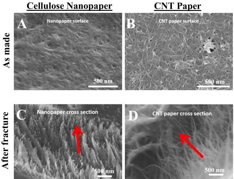
SEM images of (A) the surface of the as-made cellulose nanopaper (with a mean diameter of CNF fibers of 28 nm) and (B) the surface of the as-made CNT paper, both showing random distribution of constituent fibers. (C and D) SEM images of the cross-section of failure of the cellulose nanopaper and CNT paper, respectively, after the tensile tests. In both C and D, it is evident that the initially random network of constituent fibers aligns along the tensile loading direction indicated by the arrows.
Based on the above results, we envision the following mechanistic understanding on the exceptional mechanical properties and anomalous scaling law of cellulose nanopaper: though the increase in tensile strength of cellulose nanopaper is attributed to reduced defect size as the constituent CNF fiber size decreases (the smaller, the stronger); the simultaneous increase in toughness essentially results from the significant increase of strong hydrogen bonding among CNF fibers as their diameter decreases (and thus their surface area increases). Fig. 4 further clarifies the envisioned molecular-level toughening mechanism of cellulose nanopaper. Under tension, the initially entangled CNF network deflects and twists to align parallel to the tensile direction. As the load increases, the straightened CNF fibers begin to slide relative to each other, and the pulling-off and fracture of such fibers eventually leads to the overall failure of the nanopaper. Unlike covalent bonding, hydrogen bonding between hydroxyl groups readily reforms after bond breaking due to interfiber sliding. If a cellulose fiber fractures under tension, the fractured segments remain bonded to neighboring fibers. In other words, mechanical failure of nanopaper involves both fiber fracture and a cascade of hydrogen bond breaking and reforming events (as illustrated in Fig. 4), which dissipate a significant amount of energy, and thus result in much enhanced fracture toughness.
Fig. 4.

Envisioned molecular-level toughening mechanism of cellulose nanopaper. Failure involves a cascade of hydrogen bond forming, breaking, and reforming events, which dissipate a significant amount of energy, leading to much-enhanced fracture toughness of cellulose nanopaper.
By contrast, a SWCNT film lacks such a mechanism. Bonding between SWCNTs in the film is essentially van der Waals (vdW) forces, which are much weaker than the hydrogen bonding between hydroxyl groups in the cellulose nanopaper. Therefore, pulling out a SWCNT from the film dissipates much less energy than pulling out a CNF fiber from the cellulose nanopaper, which explains the significantly lower toughness and tensile strength of the SWCNT film compared with the cellulose nanopaper.
To confirm the above-envisioned mechanistic understanding, we carry out atomistic modeling to simulate the key deformation and failure process in both cellulose nanopaper and SWCNT films (details in SI Text).
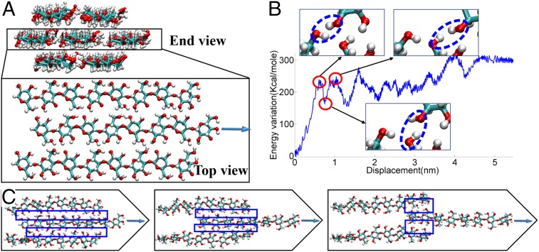
Fig. 5 illustrates the hydrogen bond breaking and reforming process by a model that is representative of the molecular-level deformation events in a cellulose nanopaper under tension. A cellulose bundle contains seven cellulose chains (each with four repeat units) that are packed in a pattern as in cellulose crystal so that one cellulose chain is completely surrounded by other six chains (Fig. 5A). We simulate the pulling out of the center chain from the bundle by applying a constant velocity on the right end of the center chain. Fig. 5B plots the variation of the total potential energy of the simulation model as a function of the pulling-out displacement, which clearly shows a zigzag fluctuation profile. Fig. 5B, Insets, reveal that the zigzag energy fluctuation captures the hydrogen bond breaking and reforming events: the potential energy ramps up to a local maximum (e.g., first peak in Fig. 5B) as the hydrogen bond stretches to the most, followed by a sudden drop of the potential energy to a local minimum (the first trough), which corresponds to the hydrogen bond with a constant velocity on the right end of the breaking and hydroxyl groups relocating to a new bonding site. The potential energy then ramps up again and reaches next local maximum, indicating the newly formed hydrogen bond stretches to the most. The above events repeat until the center chain is completely pulled out of the bundle. Fig. 5C illustrates relative cellulose chain sliding, during which a series of hydrogen bond breaking and reforming events happen when neighboring hydroxyl groups come close to each other. The boxed region shows the evolution of newly formed hydrogen bonding region during the pulling-out process. We believe that the combination of collective strength of massive hydrogen bonds and the repeated energy dissipation that is needed to completely separate two cellulose bundle surfaces (after a major series of hydrogen bond breaking and reforming events) renders the anomalous scaling law of the mechanical properties of cellulose nanopaper, which is further supported by molecular dynamics simulation of the fiber-scale deformation process in cellulose nanopaper and SWCNT films, as detailed below. The atomistic scale toughening mechanism envisioned and proved above is in line with recent studies on the interfacial energy between cellulose nanocrystals (39, 40). For example, it is shown that hydrogen bonds can always reform despite the configuration of how the CNFs intersect each other (39).
Fig. 5.
Atomistic simulations to demonstrate the hydrogen bond breaking and reforming events among cellulose molecular chains. (A) Simulation model of a cellulose bundle contains seven cellulose molecular chains. Top view only shows the middle three chains for visual clarity. (B) Variation of total potential energy as a function of the sliding displacement of the center cellulose chain out of the bundle. (Insets) Clearly shown are the hydrogen bond breaking and reforming events (dotted circles), each of which dissipates energy. (C) Relative cellulose chain-sliding, during which a series of hydrogen bond breaking and reforming events happen (in boxed region) when neighboring hydroxyl groups come close to each other.
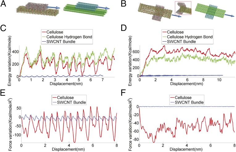
The deformation of cellulose nanopaper (or a SWCNT film) under tension is accommodated by the relative sliding between neighboring CNF fibers (or CNT bundles). Such a relative sliding can be decomposed into two sliding modes: parallel sliding and perpendicular sliding. Note that the surface area in direct contact in two neighboring fibers (e.g., within the range of effective hydrogen bonding formation or vdW interaction) is often only a small portion of the whole fiber surface. Under such a consideration, Fig. 6A shows the simulation model of the two surface areas in direct contact for parallel sliding between two CNF fibers (Fig. S9), each of which consists of an array of 6 × 3 cellulose chains, with 7 and 14 repeat units (i.e., 7.7 and 15.4 nm) in each chain, and that between two SWCNT bundles, each of which consists of 3 (15, 0) SWCNTs, with length of 7.8 nm and 15.7 nm, respectively. Fig. 6B shows the corresponding simulations models for perpendicular sliding between two CNF fibers and that between two SWCNT bundles. Fig. 6C plots the variation of total potential energy as a function of relative displacement of parallel sliding between two CNF fibers and that between two SWCNT bundles. For the case of CNF fibers, zigzag fluctuation of potential energy is of substantial amplitude. Each peak in the curve corresponds to an energy barrier that the external load needs to overcome (i.e., work done by the load) to drive the relative sliding between neighboring CNF fibers. The variation of total hydrogen bonding energy is also plotted in Fig. 6C for comparison, which matches well with that of the total potential energy in terms of both peak location and amplitude, offering strong evidence for the cascade of events of hydrogen bond breaking and reforming during the sliding process and the dominant role of hydrogen bonding in the toughening mechanism of cellulose nanopaper. In other words, the sum of all of the work associated with the repeated breaking and reforming of strong hydrogen bonds among neighboring CNF fibers before final failure essentially dominates the toughness of the cellulose nanopaper. Therefore, the scaling law of the smaller, the tougher can be readily understood by the fact that the contact area between neighboring CNF fibers (thus the total number of hydrogen bonds) increases significantly as the diameter of CNF fibers decreases. By contrast, for the case of SWCNT bundles, the potential energy variation is of much smaller amplitude. The regular wavy profile (with a period of ∼4.38 Å) suggests that the energy variation corresponds to the periodic shift of atomic stacking (with a period of 4.26 Å) between the two neighboring SWCNT bundle. Parallel sliding between neighboring SWCNT bundles dissipates much less energy than that between two CNF fibers.
Fig. 6.
Relative sliding between neighboring CNF fibers vs. SWCNT bundles. (A) Simulation models of the two surface areas in direct contact for parallel sliding between two CNF fibers (Left) and that between two SWCNT bundles (Right). (C) Variation of total potential energy as a function of relative displacement of parallel sliding between two CNF fibers (green) and that between two SWCNT bundles (blue). The contribution from hydrogen bonds between CNF fibers (red) is included for comparison. (E) The evolution of resistant force during parallel sliding of two neighboring CNF fibers (red) and two neighboring SWCNT bundles (blue). (B, D, and F) Results for the case of perpendicular sliding, in correspondence to A, C, and E, respectively.
Fig. S9.
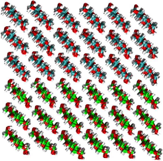
Cross-section view of the interface between two neighboring CNFs in Fig. 6. The contact surface is along (110) plane of the Iβ cellulose nanocrystal structure.
Fig. 6D plots the variation of the total potential energy as a function of relative displacement of perpendicular sliding between two CNF fibers and that between two SWCNT bundles. In perpendicular sliding mode, the difference between the two cases becomes even more drastic. For the case of CNF fibers, there is first a significant increase in the total potential energy, followed by the zigzag nature of the energy fluctuation similar to that in parallel sliding mode. The initial significant increase in total potential energy results from the severe bending of the bottom CNF fiber (Fig. 6B, Inset). Such a severe bending further confirms the strong hydrogen bonding between the two CNF fibers, a feature not existing in the SWCNT bundle case, where both SWCNT bundles remain nearly undeformed during sliding process. The severe bending of CNF fibers before perpendicular sliding occurs also contributes additional external work required to completely separate two perpendicular CNF fibers. The collective effect of these deformation features at individual CNF fiber scale leads to significant enhancement of both fracture strain and toughness of the cellulose nanopaper. However, for the case of SWCNT bundles, the variation of total potential energy is nearly negligible, which can be attributed to further reduced contact area and even weaker vdW interaction in lack of commensurate stacking between two perpendicular SWCNTs.
Fig. 6 E and F plot the evolution of resistant force when two neighboring CNF fibers (and two neighboring SWCNT bundles) slide in parallel and perpendicularly to each other, respectively. In both sliding modes, the magnitude of resistant force in CNF fiber case is substantially higher than that in the SWCNT case, shedding light on molecular scale understanding of the huge difference in tensile strength between cellulose nanopaper and SWCNT films.
Concluding Remarks
We rationally design and fabricate cellulose nanopaper by tuning the diameter of constituent cellulose fibers, which allows for what is, to our knowledge, the first-of-its-kind investigation of the size dependence of mechanical properties of cellulose nanopaper. Surprisingly, we find that both the ultimate tensile strength and toughness of the cellulose nanopaper increase significantly as the constituent cellulose fiber diameter decreases, suggesting an anomalous but highly desirable scaling law of mechanical properties: the smaller, the stronger and the tougher. The increase in tensile strength of cellulose nanopaper is attributed to reduced intrinsic defect size as the constituent cellulose fiber size decreases. A fracture mechanics model predicts that the tensile strength of cellulose nanopaper inversely scales with the square root of cellulose fiber diameter, in excellent agreement with experimental measurement over three orders of magnitude of fiber diameter. The simultaneous increase in toughness essentially results from the significant increase of strong hydrogen bonding among cellulose fibers as their diameter decreases. Further atomistic simulations reveal the key mechanism underlying this unconventional scaling law of mechanical properties: rich hydroxyl groups along cellulose molecular chains allow for facile formation and reformation of strong hydrogen bonding among neighboring molecular chains, which in turn dictate significantly enhanced resistance force and energy dissipation during intercellulose fiber sliding, and thus lead to both high tensile strength and toughness of the cellulose nanopaper. Such mechanistic understanding is further supported by control experiment, in which films made of SWCNT bundles of diameter comparable to that of cellulose fibers are shown to have drastically lower tensile strength and toughness, essentially due to rather weak vdW-type interactions in lieu of strong hydrogen bonding among building blocks.
The findings from the present study shed fundamental insight on the long-sought strategy addressing the conflict between strength vs. toughness in engineering material design by envisioning a bottom-up design strategy to achieve both high strength and toughness that is generally applicable for a wide range of other material building blocks. The opportunities are abundant and multifaceted. There exists a wide variety of other biodegradable cellulose fibers and manmade fibers, with rich features in morphology, length, topology, crystallinity, and surface groups that can be further leveraged to enable both strong and tough cellulose based materials under the same bottom-up design strategy (41–46). It is well established that functional groups can be introduced to the surface and ends of CNTs (47–49). Properly functionalized CNTs (e.g., with carboxyl groups) can enable strong inter-CNT bonding and smaller CNT bundle size, holding promise toward strong and tough CNT films, another long-sought solution in nanocarbon-based materials. The fundamental bottom-up strategy can essentially go beyond 1D building blocks (tubes, wires, filaments) toward 2D building blocks [e.g., atomic layers of graphene oxide (GO), boron nitride, and molybdenum disulfide] and 1D/2D hybrids. For example, it has been recently shown that hybrid microfibers containing well-aligned and mixed 2D GO sheets and 1D CNF fibers are both much stronger and tougher than the microfibers made of pure GO sheets or CNF fibers, due to synergistic enhancement of bonding between GO and CNF fibers (50). These fertile opportunities could lead toward a novel class of engineering materials that are both strong and tough with an array of potential applications, such as lightweight composites, flexible paper electronics, and energy devices.
Materials and Methods
The CNF dispersion is degassed for 20 min in a bath sonicator until no bubbles are observed in the dispersion. The dispersion is poured into the filtration apparatus containing a nitrocellulose ester filter membrane with a 0.65-μm pore size. The filtration time depends on the desired nanopaper thickness and CNF diameter. After filtration, a strong gel forms on top of the filter membrane. This gel “cake” is sandwiched between two smooth substrates and placed in a 40 °C oven for 10–15 min. The final nanopaper with a 90-mm diameter, 30- to 50-μm thickness, and ∼1.2 g/cm3 density is obtained after a 70 °C hot press for 10–15 min. For control experiment, we prepare regular paper from the Kraft bleached softwood (Southern Yellow Pine) pulp via filtration with the same mass per area and the same pressure as the nanopaper. The regular paper thickness is ∼60 µm, with a density ∼0.8 g/cm3.
SI Text
CNF Fibers with Different Diameters.
CNF fibers with diameters ranging from tens to hundreds of nanometers are produced by (2,2,6,6-tetramethylpiperidin-1-yl)oxidanyl (TEMPO) oxidation. A total of 5 g of Kraft bleached softwood (Southern Yellow Pine) pulp is suspended in 250 mL deionized water containing 0.5 mmol TEMPO and 5 mmol NaBr. The TEMPO mediated oxidation is initiated with the addition of 50 mmol NaClO. The pH is maintained at 10.0 with 1 mol/L NaOH solution. The whole process is maintained under stirring (IKA RW20 digital mixer) for 2–3 h. The resulting pulp is washed by filtration and stored in a cold room at 4 °C for further analysis and treatment. Mechanical treatment of the TEMPO oxidized fibers in a microfluidizer at different pressures further reduces the fiber diameter. An aqueous solution of 1.0% concentrated fiber is then treated in a Microfludizer Processor M-110EH at different pressures. Fibers of 28 and 11 nm diameters are obtained at pressures of 10,000 and 26,000 psi, respectively. Kajaani FS 300 (Metso) was used for native fiber analysis. TEM experiments JEOL JEM 2100 are performed at an accelerating voltage of 200 kV. The individual fiber morphology is obtained with Hitachi SU-70 field emission SEM. A Veeco MultiMode atomic force microscope (Veeco Instruments Inc.) equipped with a Tap300GD-G silicon probe (Budget Sensors; 10-nm tip radius) and operated in tapping mode in ambient conditions is used to image the morphology of CNF and the surface of the nanopaper.
Characterization of Cellulose Nanopaper.
Fig. S2 shows the characterization of these cellulose fibers using optical scope, SEM, and HRTEM, as well as the diameter distribution histograms.
Regular paper is a porous random network of cellulose fibers, with a large number of cavities filled with air. Light scatters on the fiber–air interface, which makes regular paper opaque. When air is moved out of the paper, both its transparency and density increase. The optical transmittance of the nanopaper was tested with a UV-Vis Spectrometer Lambda 35 (PerkinElmer), and the transmittance was measured between 1,100 and 250 nm using a Shimadzu UV-Vis spectrometer. Fig. S3A shows the highly transparent cellulose nanopaper, with an optical total transmittance of 92% in the visible wavelength range (Fig. S3B). Fig. S3A, Inset, highlights the fibrous structure of the cellulose nanopaper. Fig. S3 C and D are AFM images of the surfaces of cellulose nanopaper made from CNF fibers with mean diameters of 28 and 11 nm, respectively, showing the random and entangled CNF fiber network structure in the nanopaper. For the 11-nm diameter CNF, the surface morphology observed in AFM (Fig. S3D) is similar to that of a CNT film.
Preparation of Single-Walled Carbon Nanotube Films.
The freestanding SWCNT films are produced via the wet method with vacuum filtration. The SWCNTs were purchased from Carbon Solution Inc. A total of 1 mg/mL SWCNT in 1% sodium dodecyl benzene sulfonate solution are bath-sonicated for 5 min and probe sonicated with a 20% amplitude for 5 min to obtain a highly homogenous dispersion. A total of 4 mL of the solution is diluted to 20 mL and vacuum-filtered with a 200-nm pore-anodized alumina membrane (Anodisc 47; Whatman). An intact film is released from the filter after 0.5 h of filtration.
Measurement of Fracture Toughness of Cellulose Paper.
We determine the fracture toughness of cellulose paper using a method developed by Rivlin and Thomas (51).
Consider a test sample of width of , thickness of t, and height between two clamps of (Fig. S4A). A precrack of length c is introduced along the middle line between two clamps. If both and are substantially larger than , then when the sample is deformed, by separating the two clamps, in a direction parallel to the dimension , region ➀ of the sample (in the wake of the precrack, as labeled in Fig. S4A) is essentially stress-free, region ➂ is well ahead of the precrack and thus in a uniform pure-shear deformation state, and region ➁ lying between ➀ and ➂ is in a complex deformation state due to the crack tip. Moreover, another complex deformation state takes place in region ➃ due to the influence from the traction-free edge. As further illustrated in Fig. S4B, an increase in the crack length of amount measured in the undeformed state of the sample does not alter the state of strain in the region ➁ but just essentially shifts this region along the crack propagation direction by an distance of . As a result, region A grows in size by at the expense of region ➂. Thus, an increase in crack length leads to the release of elastic energy stored in a volume of of the sample in region ➂. Such an energy release drives the propagation of the crack with an increase of length of dc. Denoting the fracture toughness of the cellulose paper as , and the strain energy density in region ➂ as , the above consideration leads to .
To adapt the above method to measure the fracture toughness of the cellulose paper, we test two separate sets of samples made by the same cellulose paper, one set of samples have no precrack, and the other set are precut. For all samples, = 30 mm and =10 mm. The thickness for cellulose paper with mean cellulose fiber size of 11 nm, 28 nm, and 27 μm is measured to be 25.6, 57.1, and 270 μm, respectively. The uncut sample is pulled to measure the load displacement curve of the cellulose paper under a uniform pure-shear deformation state (no need to stretch the uncut sample to rupture). When the two clamps are pulled to a separation distance of , the area beneath the load displacement curve defines the work done by the applied load, . The precut samples are prepared by using a razor to cut into the cellulose paper 15 mm (). The precut sample is pulled and the critical distance between the clamps when the precrack turns into a propagating crack is recorded. Then the strain energy density of the cellulose paper under a uniform pure-shear deformation state can be determined to be . Therefore, the fracture toughness of the cellulose paper can be given by .
Fig. S5 A–C plots the load displacement curves of the uncut and precut samples with mean cellulose fiber diameter of 11 nm, 28 nm, and 27 μm, respectively. Fig. S5D plots the fracture toughness of the cellulose paper measured by the abovementioned method as a function of the mean cellulose fiber diameter, clearly showing a scaling law of the smaller, the tougher. For example, the fracture toughness of the cellulose paper increases more than 10 times (from 143.3 to 1481.4 J/m2) as the mean cellulose fiber diameter decreases from 27 to 11 nm, respectively.
A Fracture Mechanics Model on Size Dependence of Tensile Strength of Cellulose Paper.
When a preexisting defect (e.g., a crack in a cellulose fiber as depicted in Fig. S6) propagates and leads to the fracture of a cellulose fiber, the elastic energy stored in the fiber under tension is relaxed. The reduction in elastic energy associated with crack propagation over a unit area defines an energy release rate , the driving force for fiber fracture. Assuming cellulose fibers are an elastic material, dimensional analysis dictates that the energy release rate takes the form
| [S1] |
where is the Young’s modulus of the cellulose fiber, is the tensile stress, D is the fiber diameter, and denotes the feature size of the preexisting defect. is a dimensionless parameter on the order of unity, which essentially depends on the dimensionless length ratio . The preexisting defect can advance unstably and cause the fracture of a cellulose fiber when , where is the surface energy per unit area of the cellulose fiber. Therefore, the tensile strength of a cellulose fiber is given by
| [S2] |
Note that the tensile failure of the cellulose paper often originates from the fracture of the weakest cellulose fibers, followed by a cascade of fiber fracture events. As such, the ultimate tensile strength of the cellulose paper corresponds to the case when reaches its maximum value . Assuming cellulose fibers of all diameters have a circular cross-section, is independent of fiber diameter, and thus a constant. Reorganizing Eq. S2 yields
| [S3] |
In other words, the tensile strength of cellulose paper is proportional to the inverse of the square root of cellulose fiber diameter. Eq. S3 can be used to fit the ultimate tensile strength vs. mean cellulose diameter measurement data. As shown in Fig. 3D, the curve-fitting based on Eq. S3 is in excellent agreement with experimental data over three orders of magnitude of the cellulose diameter. The constant in Eq. S3 has the same dimension as the stress intensity factor and curve-fitting with experimental measurement yields a value of the constant ∼.
Tensile Tests of Cellulose Paper and CNT Films.
Tensile tests of the cellulose paper and CNT films are performed using a Tinius Olsen H25KT universal material strength testing machine. The machine is operated under head cross displacement control at a constant rate of 5 mm/min (with a strain rate of 20% per minute). The load cell has a maximum capacity of 25 kN, minimum force resolution of 0.83 N, and minimum displacement resolution of 0.004 mm. Five specimens are prepared for each sample, and each specimen strip is cut to 5 × 50 mm. All specimens are conditioned for 24 h at 50% humidity and 23 ± 1.0 °C before testing.
Given that the cellulose paper is essentially a dense network of cellulose fibrils, the deformation and failure mechanisms of interfibril sliding followed by individual fibril fracture or pulling-off of network are expected to be in place in both crack initiation (e.g., by dissipating more energy to initiate a crack) and crack propagation (e.g., by reducing stress concentration at the crack tip by cellulose fibril bridging in the wake of a propagating crack). Fig. S8 shows an SEM image of cellulose nanopaper at the cross-section of failure after the tensile test. The initially random distributed CNF fibers are shown to be aligned along the tensile loading direction at failure. The spiky extrusions and broken cellulose fibrils along the failure cross-section offer evidence of the cellulose fibril bridging during the fracture of the sample.
Atomistic Simulation.
The full atomistic simulations uses the ReaxFF potential (52) as implemented in the Large-Scale Atomic/Molecular Massively Parallel Simulator (53) simulation package, developed for carbon–carbon interactions and hydrocarbon oxidation. ReaxFF force field was developed via first principle and is also able to account for various nonbonded interactions including an explicit energy expression for hydrogen bonds. The simulations were subjected to a microcanonical ensemble, carried out at a temperature of 5 K, for the purpose of suppressing thermal noise to clearly reveal the fine feature of the hydrogen bond stick-slip event. The time step is set to 0.5 fs. The energy data points were sampled on every 200 time steps, and the force data points were sampled on every 1,000 time steps. For simulations in Fig. 5, the carbon atoms on the very left end (in the side view) of the six surrounding CNF chains are confined to only have the degree of freedom perpendicular to the pulling direction of the central CNF chain, the pulling of which is enabled by pulling the carbon atom with a velocity of 0.001 Å/fs on its very right end (in the side view). For simulations in Fig. 6, the two ends of each CNF fiber (or SWCNT bundle) are modeled as rigid bodies with the condition that a constant velocity of 0.001 Å/fs along the pulling direction is applied. For Fig. 6A, the pulling is applied to the ends of the longer CNF fiber (or SWCNT bundle) while the ends of the shorter CNF fiber (or SWCNT bundle) are hold still. For Fig. 6B, the pulling is applied to the ends of the longer CNF fiber (or SWCNT bundle). The force is calculated by summing up the force component along the sliding direction of all of the atoms in the shorter CNF fiber (or SWCNT bundle).
For simulations in Fig. 6, a half Iβ cellulose nanocrystal structure (consisting of 18 cellulose chains) is used for each of the top and the bottom CNFs. The contact surface is along (110) plane (Fig. S9).
Acknowledgments
We thank Peter Ciesielski in the National Bioenergy Center at National Renewable Energy Laboratory for the SEM characterization of Southern Yellow Pine hierarchical structure, and we acknowledge the use of the Modern Engineering Materials Instructional Laboratory at the University of Maryland for mechanical testing and the sharing of the Microfluidizer at the Biotechnology Research and Education Center. This work was supported by National Science Foundation Grants 1362256, 1069076, and 1129826 (to S.Z., Z.J., and T.L.), Department of Defense Air Force of Scientific Research Young Investigator Program FA95501310143 (L.H.), and the Maryland NanoCenter’s FabLab and NispLab.
Footnotes
The authors declare no conflict of interest.
This article is a PNAS Direct Submission.
This article contains supporting information online at www.pnas.org/lookup/suppl/doi:10.1073/pnas.1502870112/-/DCSupplemental.
References
- 1.Ritchie RO. The conflicts between strength and toughness. Nat Mater. 2011;10(11):817–822. doi: 10.1038/nmat3115. [DOI] [PubMed] [Google Scholar]
- 2.Evans AG. Perspective on the development of high-toughness ceramics. J Am Ceram Soc. 1990;73(2):187–206. [Google Scholar]
- 3.Hofmann DC, et al. Designing metallic glass matrix composites with high toughness and tensile ductility. Nature. 2008;451(7182):1085–1089. doi: 10.1038/nature06598. [DOI] [PubMed] [Google Scholar]
- 4.Launey ME, Ritchie RO. On the fracture toughness of advanced materials. Adv Mater. 2009;21(20):2103–2110. [Google Scholar]
- 5.Lu K, Lu L, Suresh S. Strengthening materials by engineering coherent internal boundaries at the nanoscale. Science. 2009;324(5925):349–352. doi: 10.1126/science.1159610. [DOI] [PubMed] [Google Scholar]
- 6.Lu L, Chen X, Huang X, Lu K. Revealing the maximum strength in nanotwinned copper. Science. 2009;323(5914):607–610. doi: 10.1126/science.1167641. [DOI] [PubMed] [Google Scholar]
- 7.Lu L, Shen Y, Chen X, Qian L, Lu K. Ultrahigh strength and high electrical conductivity in copper. Science. 2004;304(5669):422–426. doi: 10.1126/science.1092905. [DOI] [PubMed] [Google Scholar]
- 8.Zhu T, Li J. Ultra-strength materials. Prog Mater Sci. 2010;55(7):710–757. [Google Scholar]
- 9.Greer J, De Hosson J. Plasticity in small-sized metallic systems: Intrinsic versus extrinsic size effect. Prog Mater Sci. 2011;56(6):654–724. [Google Scholar]
- 10.Deng C, Sansoz F. Near-ideal strength in gold nanowires achieved through microstructural design. ACS Nano. 2009;3(10):3001–3008. doi: 10.1021/nn900668p. [DOI] [PubMed] [Google Scholar]
- 11. Anderoglu, et al. (2008) Epitaxial nanotwinned Cu films with high strength and high conductivity. Appl Phys Lett 93(8):083108.
- 12.Cao A, Wei Y, Mao S. Deformation mechanisms of face-centered-cubic metal nanowires with twin boundaries. Appl Phys Lett. 2007;90(15):151909. [Google Scholar]
- 13.Dao M, Lu L, Shen Y, Suresh S. Strength, strain-rate sensitivity and ductility of copper with nanoscale twins. Acta Mater. 2006;54(20):5421–5432. [Google Scholar]
- 14.Jang D, Li X, Gao H, Greer JR. Deformation mechanisms in nanotwinned metal nanopillars. Nat Nanotechnol. 2012;7(9):594–601. doi: 10.1038/nnano.2012.116. [DOI] [PubMed] [Google Scholar]
- 15.Li X, Wei Y, Lu L, Lu K, Gao H. Dislocation nucleation governed softening and maximum strength in nano-twinned metals. Nature. 2010;464(7290):877–880. doi: 10.1038/nature08929. [DOI] [PubMed] [Google Scholar]
- 16.Launey ME. Fracture toughness and crack resistance curve behavior in metallic glass matrix composites. Appl Phys Lett. 2009;94:241910–241913. [Google Scholar]
- 17.Ritchie RO. Mechanisms of fatigue crack-propagation in metals, ceramics and composites: Role of crack tip shielding. Mater Sci Eng A. 1988;103(1):15–28. [Google Scholar]
- 18.Vashishth D. Rising crack-growth-resistance behavior in cortical bone: Implications for toughness measurements. J Biomech. 2004;37(6):943–946. doi: 10.1016/j.jbiomech.2003.11.003. [DOI] [PubMed] [Google Scholar]
- 19.Conner RD, Johnson WL, Paton NE, Nix WD. Shear bands and cracking of metallic glass plates in bending. J Appl Phys. 2003;94(2):904–911. [Google Scholar]
- 20.Jang D, Greer JR. Transition from a strong-yet-brittle to a stronger-and-ductile state by size reduction of metallic glasses. Nat Mater. 2010;9(3):215–219. doi: 10.1038/nmat2622. [DOI] [PubMed] [Google Scholar]
- 21.Demetriou MD, et al. A damage-tolerant glass. Nat Mater. 2011;10(2):123–128. doi: 10.1038/nmat2930. [DOI] [PubMed] [Google Scholar]
- 22.Koester KJ, Ager JW, 3rd, Ritchie RO. The true toughness of human cortical bone measured with realistically short cracks. Nat Mater. 2008;7(8):672–677. doi: 10.1038/nmat2221. [DOI] [PubMed] [Google Scholar]
- 23.Launey ME, Buehler MJ, Ritchie RO. On the mechanistic origins of toughness in bone. Annu Rev Mater Res. 2010;40:25–53. [Google Scholar]
- 24.Nalla RK, Kinney JH, Ritchie RO. Mechanistic fracture criteria for the failure of human cortical bone. Nat Mater. 2003;2(3):164–168. doi: 10.1038/nmat832. [DOI] [PubMed] [Google Scholar]
- 25.Weiner S, Wagner HD. The material bone: Structural-mechanical functional relations. Annu Rev Mater Sci. 1998;28:271–298. [Google Scholar]
- 26.Gupta HS, et al. Nanoscale deformation mechanisms in bone. Nano Lett. 2005;5(10):2108–2111. doi: 10.1021/nl051584b. [DOI] [PubMed] [Google Scholar]
- 27.Moon RJ, Martini A, Nairn J, Simonsen J, Youngblood J. Cellulose nanomaterials review: Structure, properties and nanocomposites. Chem Soc Rev. 2011;40(7):3941–3994. doi: 10.1039/c0cs00108b. [DOI] [PubMed] [Google Scholar]
- 28.Klemm D, et al. Nanocelluloses: A new family of nature-based materials. Angew Chem Int Ed Engl. 2011;50(24):5438–5466. doi: 10.1002/anie.201001273. [DOI] [PubMed] [Google Scholar]
- 29.Klemm D, Heublein B, Fink HP, Bohn A. Cellulose: Fascinating biopolymer and sustainable raw material. Angew Chem Int Ed Engl. 2005;44(22):3358–3393. doi: 10.1002/anie.200460587. [DOI] [PubMed] [Google Scholar]
- 30.Abdul Khalil HPS, Bhat AH, Ireana Yusra AF. Green composites from sustainable cellulose nanofibrils: A review. Carbohydr Polym. 2012;87:963–979. [Google Scholar]
- 31.Chinga-Carrasco G. Cellulose fibres, nanofibrils and microfibrils: The morphological sequence of MFC components from a plant physiology and fibre technology point of view. Nanoscale Res Lett. 2011;6(1):417. doi: 10.1186/1556-276X-6-417. [DOI] [PMC free article] [PubMed] [Google Scholar]
- 32.Lavoine N, Desloges I, Dufresne A, Bras J. Microfibrillated cellulose—its barrier properties and applications in cellulosic materials: A review. Carbohydr Polym. 2012;90(2):735–764. doi: 10.1016/j.carbpol.2012.05.026. [DOI] [PubMed] [Google Scholar]
- 33.Isogai A, Saito T, Fukuzumi H. TEMPO-oxidized cellulose nanofibers. Nanoscale. 2011;3(1):71–85. doi: 10.1039/c0nr00583e. [DOI] [PubMed] [Google Scholar]
- 34.Azizi Samir MAS, Alloin F, Dufresne A. Review of recent research into cellulosic whiskers, their properties and their application in nanocomposite field. Biomacromolecules. 2005;6(2):612–626. doi: 10.1021/bm0493685. [DOI] [PubMed] [Google Scholar]
- 35.Zhu H, et al. Tin anode for sodium-ion batteries using natural wood fiber as a mechanical buffer and electrolyte reservoir. Nano Lett. 2013;13(7):3093–3100. doi: 10.1021/nl400998t. [DOI] [PubMed] [Google Scholar]
- 36.Fang Z, et al. Novel nanostructured paper with ultrahigh transparency and ultrahigh haze for solar cells. Nano Lett. 2014;14(2):765–773. doi: 10.1021/nl404101p. [DOI] [PubMed] [Google Scholar]
- 37.Sehaqui H, Allais M, Zhou Q, Berglund LA. Wood cellulose biocomposites with fibrous structures at micro- and nanoscale. Compos Sci Technol. 2011;71(3):382–387. [Google Scholar]
- 38.Sreekumar TV, et al. Single wall carbon nano tube films. Chem Mater. 2003;15(1):175–178. [Google Scholar]
- 39.Wu X, Moon RJ, Martini A. Atomistic simulation of frictional sliding between cellulose IÎ2 nanocrystals. Tribol Lett. 2013;52:395–405. [Google Scholar]
- 40.Sinko R, Keten S. Traction–separation laws and stick-slip shear phenomenon of interfaces between cellulose nanocrystals. J Mech Phys Solids. 2015;78:526–539. [Google Scholar]
- 41.Eichhorn SJ, et al. Review: Current international research into cellulose nanofibres and nanocomposites. J Mater Sci. 2010;45(1):1–33. doi: 10.1007/s10853-020-04961-4. [DOI] [PMC free article] [PubMed] [Google Scholar]
- 42.Fernandes SCM, et al. Novel transparent nanocomposite films based on chitosan and bacterial cellulose. Green Chem. 2009;11(12):2023–2029. [Google Scholar]
- 43.Juntaro J, et al. Creating hierarchical structures in renewable composites by attaching bacterial cellulose onto sisal fibers. Adv Mater. 2008;20(16):3122–3126. [Google Scholar]
- 44.Yano H, et al. Optically transparent composites reinforced with networks of bacterial nanofibers. Adv Mater. 2005;17(2):153–155. [Google Scholar]
- 45.Smole MS, Hribernik S, Kleinschek KS, Kreže T. Plant fibres for textile and technical applications. In: Stanislaw G, Andrzej S, editors. Advances in Agrophysical Research. InTech; Rijeka, Croatia: 2013. pp. 370–398. [Google Scholar]
- 46.Walther A, Timonen JVI, Díez I, Laukkanen A, Ikkala O. Multifunctional high-performance biofibers based on wet-extrusion of renewable native cellulose nanofibrils. Adv Mater. 2011;23(26):2924–2928. doi: 10.1002/adma.201100580. [DOI] [PubMed] [Google Scholar]
- 47.Felten A, Bittencourt C, Pireaux JJ, Van Lier G, Charlier JC. Radio-frequency plasma functionalization of carbon nanotubes surface O2, NH3, and CF4 treatments. J Appl Phys. 2005;98(7):074308–074309. [Google Scholar]
- 48.Hu L, Hecht DS, Grüner G. Carbon nanotube thin films: Fabrication, properties, and applications. Chem Rev. 2010;110(10):5790–5844. doi: 10.1021/cr9002962. [DOI] [PubMed] [Google Scholar]
- 49.Yuan WZ, et al. Wrapping carbon nanotubes in pyrene-containing poly(phenylacetylene) chains: Solubility, stability, light emission, and surface photovoltaic properties. Macromolecules. 2006;39(23):8011–8020. [Google Scholar]
- 50.Li Y, et al. Hybridizing wood cellulose and graphene oxide toward high-performance fibers. NPG Asia Mater. 2015;7:e150. [Google Scholar]
- 51.Rivlin RS, Thomas AG. Rupture of rubber. I. Characteristic energy for tearing. J Polym Sci Polym Phys Ed. 1953;10(3):291–318. [Google Scholar]
- 52.Mattsson T, et al. First-principles and classical molecular dynamics simulation of shocked polymers. Phys Rev B. 2010;81:054103–054109. [Google Scholar]
- 53.Plimpton S. Fast parallel algorithms for short-range molecular-dynamics. J Comput Phys. 1995;117(1):1–19. [Google Scholar]


