Significance
In contemporary spintronics, spin transfer torque exerted by a spin-polarized current is often used to control magnetic domains. In addition to it, magnons in both metals and insulators are now regarded as an attractive alternative to deliver and exchange spin momentum with magnetic domain walls. We demonstrate that (i) magnetoelastic waves (coupled propagation of phonon and magnon) can be generated in an iron garnet film by ultrafast laser pulses, to be a versatile source of spin momentum, and (ii) this traveling spin excitation drives the magnetic domains; more efficiently for those with steeper curvatures at the wall. The latter, the emergent electromagnetic response of the curved domain wall, can be understood by expanding the Thiele equation.
Keywords: spintronics, photomagnetic effect, spin wave, magnetic domain wall, skyrmion
Abstract
Precise control of magnetic domain walls continues to be a central topic in the field of spintronics to boost infotech, logic, and memory applications. One way is to drive the domain wall by current in metals. In insulators, the incoherent flow of phonons and magnons induced by the temperature gradient can carry the spins, i.e., spin Seebeck effect, but the spatial and time dependence is difficult to control. Here, we report that coherent phonons hybridized with spin waves, magnetoelastic waves, can drive magnetic bubble domains, or curved domain walls, in an iron garnet, which are excited by ultrafast laser pulses at a nonabsorbing photon energy. These magnetoelastic waves were imaged by time-resolved Faraday microscopy, and the resultant spin transfer force was evaluated to be larger for domain walls with steeper curvature. This will pave a path for the rapid spatiotemporal control of magnetic textures in insulating magnets.
To materialize integrated spintronics (1, 2), it is essential to avoid excess energy to generate the control magnetic field by electric current. Therefore, the practical manipulation of the magnetic domain wall (DW) is now being realized by spin transfer torque generated from spin-polarized charge current in metals (3) and from flow of magnons in insulators (4), e.g., via the spin Seebeck effect (5, 6). On the other hand, the optical control, aiming at ultrafast, nonthermal, and remote access to magnetic domains, remains elusive even after the discoveries of photomagnetic domain manipulation (7, 8), laser-induced magnetization reversal (9), and directional generation of magnetostatic waves (10). The main difficulty has been due to the weak coupling between photon and spin; in general, only a fraction of total spin moment can be modulated by visible–to–near-infrared photoexcitation if one wants to avoid extensive heating in the electron/lattice sectors. Here, we report an alternative optical process of generating coherent magnons, via magnetoelastic couplings as originally proposed by Kittel (11), and their interaction with magnetic domains, with a special attention to the geometry of the DWs.
A magnetic bubble generally refers to a cylinder-like magnetic domain formed by long-range dipolar interactions, in which the magnetization is antiparallel to external magnetic field at the center and is parallel at its periphery with various types of DW spin windings. Having experienced an intense study in the 1960s and 1970s for nonvolatile memory applications (12), there is a recent reawakening of interest in magnetic bubbles, owing to the experimental discovery of magnetic skyrmions in noncentrosymmetric helimagnets with relativistic Dzyaloshinskii–Moriya (DM) interactions (13–15). These skyrmions have noncoplanar spin-swirling textures, wrapping the unit sphere an integer number of times (15), and can be topologically equivalent to magnetic bubbles without Bloch lines at the wall (called type I) (16). One apparent difference shows up in their size; the diameter of skyrmions by the DM interaction typically ranges from 3 to 200 nm, whereas those by dipolar interaction from 100 nm to several micrometers (15). Various emergent interactions characterizing skyrmions have been revealed recently, such as the topological Hall effect, skyrmion Hall effect, and multiferroic behaviors in the insulating background, etc., some of which can be visualized under the Lorentz transmission electron microscope as current-driven and magnon-driven kinetics (17, 18). With the emergent electromagnetism induced by its steric and topological spin alignments, the skyrmion can function as an externally operable information carrier. From the viewpoint of topology, the dynamics of the magnetic bubble have direct relations with those of the skyrmion, with a definite advantage that bubbles can readily be observed under polarized optical microscopes. By convention, we refer to the circular magnetic domains in iron garnets as magnetic bubbles in the following, although some of them can be called skyrmions as well.
One can manipulate magnetic bubbles by external magnetic-field gradients or thermal ones; the latter have been realized by heating the sample by a focused laser (heat mode) at absorbing photon energy, creating a gradient of the order of 10 K/μm (19, 20). On the other hand, it has been demonstrated that skyrmions formed by the DM interaction can be driven through the interaction with spin-polarized charge current of ultralow density (∼106 A⋅m−2, five to six orders of magnitude smaller than that for the DW motion in ferromagnets) (17, 21), or by thermally excited magnon flow (18), owing to their emergent electromagnetic responses (15).
Considering the recent advances in the ultrafast optical control of spin ensembles (22), as well as in the understanding of interactions of spin wave and spin current with magnetic nanostructures, it is interesting to examine the photon–bubble (or photon–skyrmion) interaction. In particular, we focus on the magnetoelastic wave, a propagating mode of coupled sound and spin waves, which is capable of carrying a spin excitation more efficiently than thermally excited incoherent phonons. A phonon is a quantum of the lattice distortion wave, and a magnon is that of the spin wave. In a magnet, the crystal lattice experiences a small deformation when magnetized; such magnetostriction depends on the crystal symmetry and the direction of magnetization in the presence of spin–orbit interaction. When a sound wave travels in this magnetic crystal, the propagating lattice distortion tilts the spin out from its equilibrium direction through the magnetoelastic coupling (11). This coupling is enhanced at the resonant magnetoelastic mode when the original dispersions of phonon and magnon cross. The interaction between magnetoelastic waves and magnetic bubbles in insulating iron garnets as shown below will be readily generalized to the case of skyrmions in insulating chiral magnets.
Results
Threshold Optical Power to Drive Magnetic Bubbles.
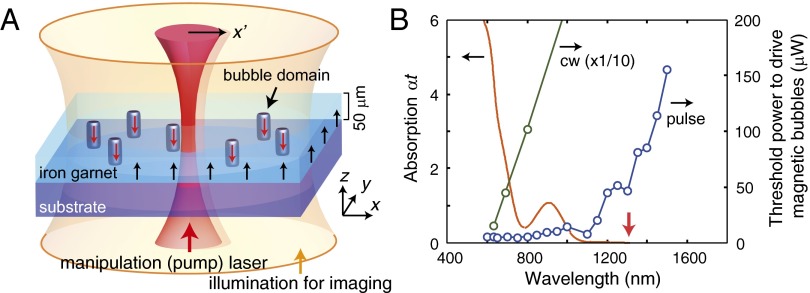
Fig. 1A illustrates our experimental setup. In an iron garnet film, the bubble phase appears with the application of out-of-plane magnetic field slightly below the magnetic saturation. We used focused pump lasers, either ultrashort pulse (120-fs width, 1-kHz repetition) or continuous wave (CW), and studied how the bubbles (or domain walls) interact with the laser lights under an optical microscope (see Supporting Information for detail). The threshold laser power to drive individual bubbles is indicated in Fig. 1B. With respect to the optical absorption, it is observed that the pulse laser can move bubbles even with the wavelength within the optical gap (∼1,100 nm), whereas the CW laser cannot. This fact is distinct from the reported heat mode operation of the magnetic bubbles (19, 20) and the photomagnetic manipulation of domain walls (7, 8), as discussed below.
Fig. 1.
Experimental setup and action spectra for the photodrive of magnetic bubbles. (A) Schematic illustration of magnetic bubbles in an iron garnet film interacting with focused manipulation (pump) laser. (B) Threshold laser power for driving magnetic bubbles plotted together with the absorption spectrum of an iron garnet film. The average power at 1 kHz is adopted for the pulse laser to directly compare with the CW laser source. The wavelength used for generating magnetoelastic waves (1,300 nm) in the main text is indicated with a red arrow.
Optical Generation of Magnetoelastic Waves.
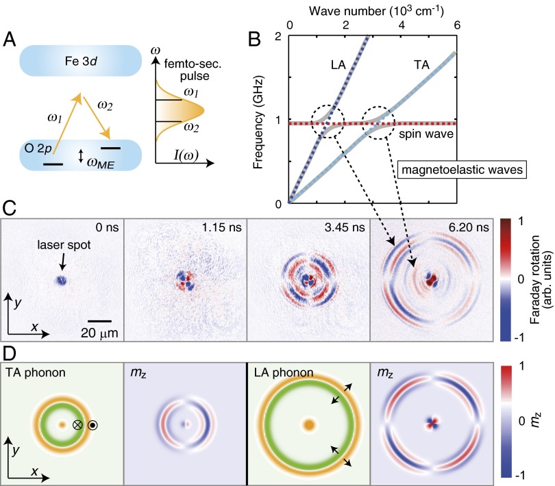
Now, we visualize the driving force for the non-heat mode manipulation of magnetic bubbles. It is well known that one can excite phonons and magnons in insulating materials by an impulsive stimulated Raman process of ultrafast optical excitation (22, 23) (Fig. 2A). For iron garnet films, magnons (or spin waves) excited in this manner have been studied extensively (10, 24), called inverse-Faraday effect (25–27). Here, we use somewhat different excitations, “magnetoelastic waves” (11, 28, 29), to manipulate bubbles. Their efficiency on carrying spin moment has been exemplified recently as acoustic spin pumping (30). Fig. 2B depicts the schematic dispersion relations of an iron garnet film in our experimental conditions, where anticrossings of acoustic phonon and exchange spin wave dispersions are expected. Near the anticrossings, these waves are coupled to form magnetoelastic modes, which are imaged by time-resolved Faraday rotation as shown in Fig. 2C. For these snapshot images, the external magnetic field was applied along the x axis to erase bubble domains and avoid strong Faraday rotation from them. The successive snapshot images at 0–6.20 ns clearly illustrate a spherical wave with quadrupole-like texture propagating from the excitation spot. Considering their velocity v (31), we can assign the outer four-node patterns (v ∼ 7 km/s) to the spin wave coupled to longitudinal acoustic (LA) phonons, and the inner two-node (v ∼ 3 km/s) to the coupling to transverse acoustic (TA) phonons, respectively.
Fig. 2.
Magnetoelastic excitation in garnet films. (A) Impulsive Raman process induced by an ultrafast laser pulse. (B) Schematic dispersions of phonons and a spin wave in an iron garnet film with anticrossings via magnetoelastic interactions. (C) Faraday microscopy snapshots on the generation and propagation of magnetoelastic waves. The pump laser pulse (1,300 nm, 100 nJ) excites the longitudinal (LA) and transverse (TA) acoustic phonons coupled to the spin moments via the magnetoelastic interaction, leading to the Faraday rotation of the probe light (800 nm) arriving at the specified elapsed time. Corresponding wave modes in the dispersion relations are indicated by dotted arrows from B. The images were acquired with exposure time of 120 s under an in-plane magnetic field of 700 G applied along the x axis. (D) Simulations of the magnetoelastic action to the spin moments (as represented by induced by TA and LA phonons). Orange and green belts stand for the assumed plus/minus phonon magnitude, with the lattice displacement along the z axis for the TA phonon and along the propagation direction in the plane for the LA phonon.
These assignments can be confirmed by a simple simulation. At elapsed time much shorter than the period of precession and with the external magnetic field applied along the x axis, magnetoelastically coupled equations with linear approximation (28) may reduce to the following:
| [1] |
| [2] |
where is the spin moment along the z axis observable by Faraday rotation, γ is the gyromagnetic ratio, b is the magnetoelastic coupling constant, is the displacement vector, and is the effective magnetic field including external, demagnetization, exchange, and dipole fields. For an expected spherical strain wave (strain direction is normal to the wave front in the plane for the LA phonon and out of the plane for the TA phonon), these equations yield the spatial patterns of shown in Fig. 2D, which is in accord with the observed Faraday microscopy snapshots (Fig. 2C). In particular, only the TA mode reverses the sign of when the external magnetic field is reversed (Eq. 2), which is experimentally verified (Supporting Information). We note that since the iron garnet films used in our experiment are heavily chemically doped to support magnetic bubbles, the genuine spin waves do not appreciably propagate from the excitation spot with our excitation condition (the typical attenuation length is less than 3 μm; Supporting Information). Furthermore, the tightly focused light spot will not couple to the magnetostatic volume waves in our sample (10). When the external field is applied along the z axis, the magnetoelastic waves can be excited in a similar manner, but with less contrast in . The phonon propagation in crystals has been visualized by several experimental techniques (23); however, the spatiotemporal images of the magnetoelastic wave have seldom been observed before.
Photodrive of Magnetic Domains via Magnetoelastic Waves.
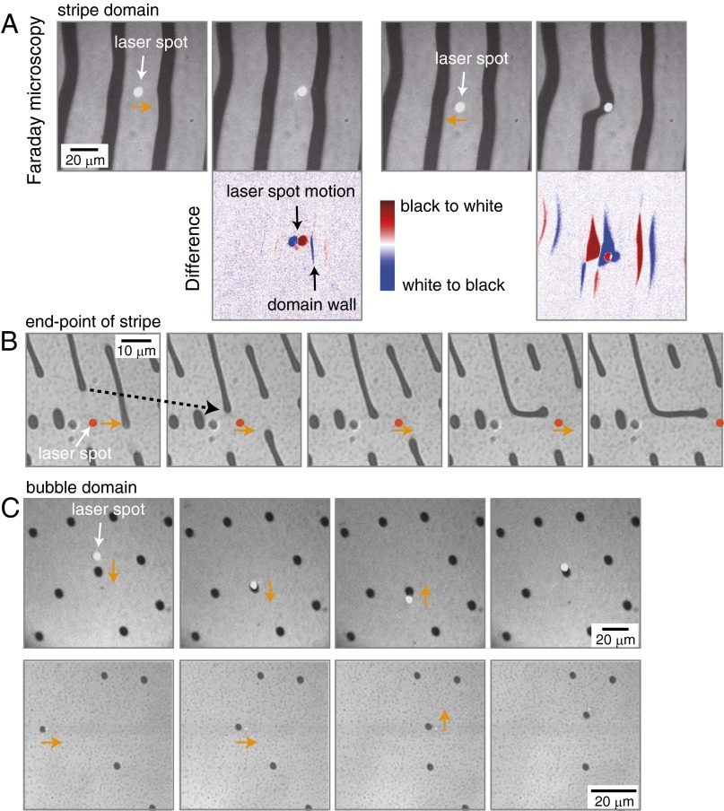
The interaction between the focused laser spot emitting magnetoelastic waves and the magnetic domains is exemplified in Fig. 3. (Corresponding movies can be found in Supporting Information.) When the pulsed laser spot approaches the stripe domain (Fig. 3A, Left), the DW is attracted toward the illumination spot, which is clearly discernible in the difference images (bottom row). The dynamics of the DWs are governed in a nontrivial manner by the wall energy, dipole interaction, pinning potential, and interactions with magnons or thermal gradient, etc., as discussed later. For some cases, we can largely distort the stripe domain via the motion of the laser spot (Fig. 3A, Right). In particular, the endpoint of the stripe domain, i.e., the half-curved spin texture, was found to be more mobile in response to the nearby pulsed photoexcitation. Fig. 3B illustrates that the endpoint of a stripe domain feels an attractive force even with some distance (typically up to 10 μm) from the excitation spot. When we scan the pump laser spot laterally, one endpoint follows the spot by bending the stripe domain while exerting the dipole forces to other stripe domains. The bubble domains, i.e., fully curved spin texture, are the most mobile (Fig. 3C). By tipping the DW of the bubble with the laser spot, we can manipulate the bubble domain laterally in any direction (Supporting Information). Note that for the heat mode operation known before, the bubbles are expected to be trapped at the center of the laser spot due to the thermal gradient (19, 20). This is not the case for the present pulsed excitation at the transparent photon energy. It is also noted that the magnetoelastic excitations (Fig. 2) and manipulation of magnetic domains (Fig. 3) are independent of the photon polarization of the pump laser (see Supporting Information for detail).
Fig. 3.
Optical manipulation of stripe domains and magnetic bubbles. (A) A pump laser spot (1,300 nm, 160 nJ) exerts an attractive force to the stripe domains as observed by Faraday microscopy with Xe lamp illumination. Bottom row shows the difference of the successive images illustrating the motion of the stripe domains upon the displacement of the laser spot (orange arrows). (B) Optically controlled elongation and bending of the stripe domain. The laser spot (emphasized with a red circle) was scanned laterally in the images, in which the initial motion of the stripe domain is indicated by a dotted arrow for clarity. Surrounding stripe domains also changed their lengths due to the dipole interaction. (C) Magnetic bubble domains are driven by the laser spot. The smaller bubbles (lower panels) can be more easily manipulated compared with the larger ones (upper panels). Corresponding movies can be found in Supporting Information.
Inverse-Faraday and Magnetoelastic Excitations in the Iron Garnet Film
Fig. S1 illustrates a transition from inverse-Faraday excitation to magnetoelastic excitation with increasing pump intensity. When the pump spot overlaps with the probe spot, with the optical setup shown in Fig. S1A, the pump-probe spectra show spin precession with the initial oscillation phase depending on the pump helicity (inverse-Faraday excitation) (10) at low pump intensity (Fig. S1B). With increasing pump intensity (above 60 nJ), additional polarization rotation of the probe light shows up, which is independent of the pump polarization (magnetoelastic excitation). When we displace the probe spot from that of the pump laser, it is seen that the genuine spin wave decays with an attenuation length of 3 μm from the pump spot center (Fig. S1C), whereas the magnetoelastic wave propagates without noticeable decay above 20 μm (Fig. S1D).
Fig. S1.
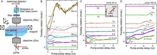
(A) Schematic illustration of the experimental setup. Here, SGGG is a nonmagnetic substrate (Materials and Methods). (B) Pump intensity dependence of the transient Faraday rotation when the pump spot overlaps with the probe spot. Pump polarization was changed between right- and left-circular ( and , respectively) at each pump intensity with the wavelength of 1,300 nm. (C and D) Probe position dependence of the transient Faraday rotation at the pump intensity of 45 nJ (C) and 100 nJ (D). The Inset of C shows the distance d between pump and probe spot, which is measured 45° off the x axis. For C and D, data were offset, proportionally to the distance d, for clarity.
Threshold Power to Drive Magnetic Bubbles
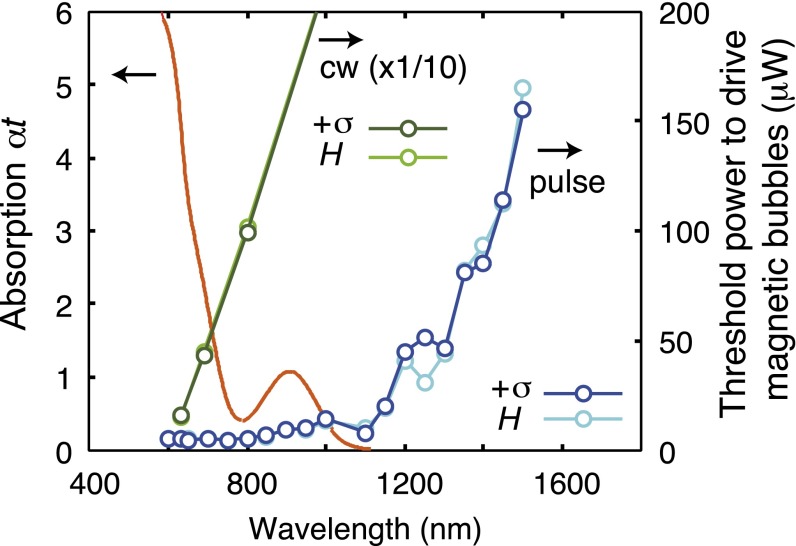
The threshold laser power shown in Fig. 1B in the main text was measured with the following procedures: (i) With the experimental condition similar to that in Fig. 3C in the main text, where the bubbles are not in the closest packing, we laterally iterate the pump spot around a magnetic bubble at 3 Hz by using a homemade piezo-controlled mirror. (ii) By observing the bubble motion at an appropriate pump power, we optimize the pump focus position along the sample z axis (the depth direction of the film; see also Movie S5 for this effect). (iii) By slowly reducing the incident power, we judge the threshold to drive the magnetic bubbles. The threshold power was reproducible, and we show the data with varying light polarization in Fig. S2.
Fig. S2.
Threshold laser power for driving magnetic bubbles. The pump polarization was changed between right-circular and linear ( and H, respectively) for both CW and pulsed light.
We also checked the speed of the bubble motion by increasing the iteration frequency of the pump spot. It was found that the bubble follows the laser spot even at the frequency above 30 Hz, which was the limit of our experimental resolution. Thus, the speed was estimated to be faster than 700 μm/s. The intrinsic mobility of the bubbles in various materials can be found in ref. 12. There, some domain walls showed the speed reaching 1 km/s.
Curvature of Domain Walls and Interaction with Spin Waves
Here, we discuss the response (with a drift velocity ) of magnetic texture to the applied spin current () and external force () described by the Thiele equation, which in the original form is expressed by the following:
| [S1] |
with
| [S2] |
and the tensor defined by the components :
| [S3] |
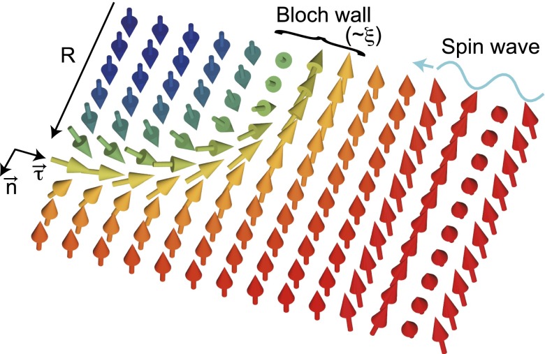
(: the unit vector along the magnetic moment) (36, 38). In the present paper, we consider the case where the DW width ξ is reasonably smaller than the size of magnetic bubble and stripe domain. Therefore, the contributions to G and come from the narrow region of the infinitesimal piece of the DW (string). We suppose a Bloch wall structure (Fig. S3) and the winding of magnetic moment is uniform in the small part of the string at with a curvature . The magnetic moment is expressed as follows:
| [S4] |
where represents the tangential vector of the string, and is the unit vector perpendicular to the thin film. We find the following:
| [S5] |
here, the angle changes from 0 to π (π to 0) when () on the left side of the DW and this determines the sign of the right-hand side of Eq. S5 and the first term in the left-hand side of Eq. 3 in the main text. The tensor is diagonalized in the orthogonal coordinates , and . Using a continuous function describing the angle ,
| [S6] |
the nonvanishing elements of the tensor are expressed to be the following:
| [S7] |
and
| [S8] |
The tensile strength T of the DW results in a restoring force on a small part at of the string. Therefore, the equation of motion of the string is given by Eq. 3.
Fig. S3.
Schematic illustration of a curved domain wall with an incoming spin wave.
With Eq. 3 in the main text, we can discuss the threshold spin current density for depinning. The two components of Eq. 3 are written explicitly as follows:
| [S9] |
where the superscripts τ and n represent the components along the tangential vector and the normal vector , respectively. From Eq. S9, one can determine the critical spin current density in the direction of to trigger the DW motion,
| [S10] |
or
| [S11] |
where represents a pinning force. Therefore,
| [S12] |
Because β () is much smaller than unity and is much longer than ξ, the relative magnitude of the two quantities in “min” in Eq. S12 depends on the situation. When , the part of the DW with the largest curvature overcomes the pinning force first. This offers a qualitative explanation of the experiment observed in Fig. 3 in the main text.
Thermal Effects
In Fig. S4, we show the estimated temperature rise in the iron garnet film. We used the experimentally deduced absorption coefficient (0.7 cm−1) and other parameters from the literature (10) to solve the heat conduction equation numerically. The maximum temperature increase obtained for the Gaussian beam (at 25 μm in the film) reads 0.6 K above the environment. Here, multiphoton or other nonlinear effects are not taken into account. However, the sample heating, e.g., by two-photon absorption, is negligible from the following reasons. (i) There is no thermally induced Faraday rotation observed in the time-resolved spectra (Fig. S1), which would appear at time zero and makes a constant offset in the Faraday rotation of the probe pulse during the following tens of nanoseconds. The rotation direction will be the same irrespective of the pump polarization, because this rotation is caused by the temperature dependence of the magnetization. (ii) When considering the two-photon absorption, the onset wavelength of the threshold power (1,100 nm) in Fig. 1B does not match the one-photon absorption edge (780 nm).
Fig. S4.

(A) Numerically evaluated temperature rise after 1 ns of the focused pump excitation (150 nJ at 1,300 nm into a 4-μmϕ beam waist) in the 50-μm-thick iron garnet film. (B) Time evolution of the thermal distribution at 25 μm in A.
In ref. 20, optical manipulation of the magnetic bubbles was reported with incident power of more than 2 mW on a 2-μm-diameter spot at 488-nm wavelength. The temperature gradient around the laser spot is estimated to be 10 K/μm, with which the motion of the bubbles were explained by the thermal force as formulated by Thiele et al. (39).
Magnetic-Field and Pump Polarization Dependencies of the Magnetoelastic Wave Propagation
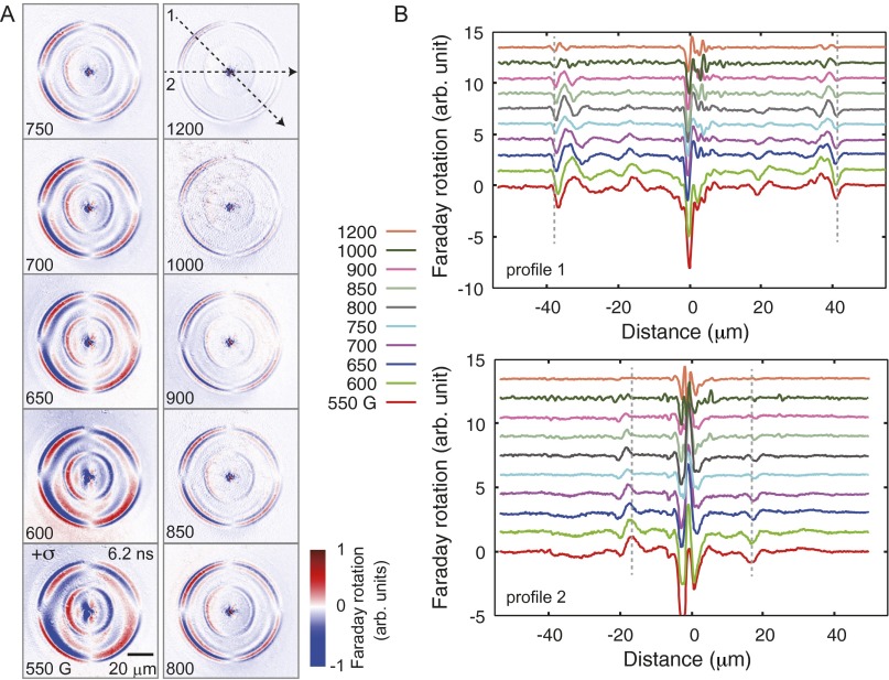
Fig. S5 shows the magnetic-field dispersion of magnetoelastic waves. With increasing external magnetic field, the spin wave branch shifts to the higher frequency as expected (Fig. 2B in the main text), while decreasing the Faraday rotation signal.
Fig. S5.
(A) Faraday microscopy snapshots taken at 6.20 ns after the pump excitation (100 nJ at 1,300 nm) under the application of varying in-plane magnetic field. The image without pump excitation is subtracted from each snapshot. The exposure time was 30 s. (B) Cross-section of the images in A along the lines 1 and 2.
Fig. S6A shows that the magnetoelastic excitation is independent of pump laser polarization (linear or circular), which is distinct from the inverse-Faraday excitation of spin waves (Fig. S1). Fig. S6B illustrates that only the magnetoelastic waves coupled to the TA phonons (inner two-node patterns) change the sign of magnetization upon the reversal of external magnetic field, consistent with the Eqs. 1 and 2 in the main text. In contrast, the Faraday rotation for both modes (coupled to the LA and the TA phonons) appeared to be flipped, as expected, when the analyzer angle is reversed around the extinction condition. The signal intensity for one of the TA modes (indicated by a black arrow in Fig. S6B) is shown in Fig. S6C. The linear dependence on the analyzer angle indicates that the imaged intensity maps reflect the Faraday rotation in the sample, and not the modulation of the transmission intensity. The latter would show a quadratic dependence on the variation of analyzer angle.
Fig. S6.
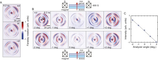
Appearance of magnetoelastic waves upon the variation of pump polarization and the analyzer angle. (A) Faraday microscopy snapshots taken at 6.20 ns after the pump excitation (120 nJ at 1,300 nm) under the application of magnetic field of 650 G with varying pump polarization. The image without pump excitation is subtracted from each snapshot. (B) Angle of the analyzer (Glan Laser prism) was shifted up to 2° from the extinction condition to illustrate the contrast reversal. The direction of magnetic field (600 G) was reversed for the top and the bottom rows as indicated by the schematics. The exposure time was 30 s. SGGG is a nonmagnetic substrate. (C) Signal intensity at the position indicated by a black arrow in C, as a function of analyzer angle. The solid line shows a linear fit.
Discussion
There are several possible mechanisms to explain the observed attractive force acting between the magnetic bubble and the laser spot: (i) thermal gradient force (heat mode) (19, 20), (ii) photoinduced anisotropy (7, 8), (iii) thermally excited magnons, (iv) optically excited magnons, and (v) magnetoelastic waves. For case i, we estimate the temperature rise of the iron garnet film just after the pump excitation at nonabsorbing photon energy to be less than 0.6 K in the 4-μmϕ Gaussian spot (Supporting Information), which is much less than the required temperature gradient for the heat mode operation of bubbles (19, 20) over a 10-μm distance (Fig. 3B). We note that there is no thermally induced Faraday rotation observed upon the pump excitation (Supporting Information). Case ii requires dopants with strong magnetic anisotropy and is sensitive to the incident polarization, which is not observed here. We can also exclude case iii by the striking difference between CW and pulsed laser excitations. The thermally (and thus incoherently) excited low-energy magnons are not relevant in our experiment. For case iv, as discussed above, the photoexcited spin waves do not propagate appreciably in our garnet films. Furthermore, photoexcited magnetostatic volume waves (10) should be strongly dependent on the pump photon polarization (linear or circular), which is not the case here (Supporting Information). Therefore, we propose that the magnetoelastic wave, case v, carrying a spin excitation, is the main driving force for the manipulation of magnetic domains. In practice, we observed a transition from spin wave to magnetoelastic wave excitations by increasing excitation intensity, which nicely corresponds to the threshold of the domain manipulation (Supporting Information). Because the nonabsorbing pump laser is used for the excitation, we expect that these magnetoelastic waves are generated by the stimulated Raman process, similar to the case of inverse-Faraday effect (25–27). The magnetic bubbles are transiently excited through the interaction with magnetoelastic waves, gaining an energy to overcome the pinning potentials, and being attracted toward the laser spot by the spin transfer torque. Because a possible phonon–DW interaction inhibits the motion of the domains (4) in the present case, we continue our discussion by concentrating only on the spin part of the magnetoelastic waves.
It is known that magnetic DWs (4, 32–35) and skyrmions (36, 37) move against the propagating spin waves to conserve total momentum, as predicted using the Landau–Lifshitz–Gilbert and Thiele equations. For a curved DW, one can generalize the Thiele equation to treat space- and time-dependent deformation. The tilting of magnetic moments with respect to the z axis is well confined in a narrow DW region; therefore, the dynamics of the DW is effectively expressed as motion of a “string” parameterized as where l is the length measured along the string and t is time. Define the tangential unit vector , and the normal vector (: the unit vector normal to the thin film). The equation of motion for a small part at due to the applied spin current of the spin wave is given by the following (Supporting Information):
| [3] |
where is the local drift velocity of DW (12). The first term describes the Magnus force. In the Bloch wall structure preferred by the dipolar interaction, the winding plane of the magnetic moment is perpendicular to the normal vector , and the curved DW possesses a solid angle of the magnetic texture (scalar spin chirality) proportional to the curvature of the string. The second and third terms represent the dissipation, where ξ is the DW width, α is the Gilbert damping constant, and β is the nonadiabatic effect. The dimensionless constants and are of the order of unity. The fourth term is the tension where T is the tensile strength of the DW. In the final term, denotes the external forces due to the pinning of DW, inhomogeneity of the sample, and so on. From Eq. 3, one can see that the portion with large curvature is subject to a stronger Magnus force, and driven by the spin current of the spin wave excitations more efficiently as discussed above. (See Supporting Information on the threshold spin current density for the depinning.)
Our experiments revealed that we can excite magnetoelastic waves in iron garnet films by an ultrafast optical excitation at nonabsorbing photon energy, realizing a local and coherent source of spin waves without generating excessive heat. It is also demonstrated that the excited magnetoelastic waves can drive magnetic DWs, more efficiently when they have steeper curvatures or in an extreme case form bubbles. The dynamics of magnetic bubbles can be generalized to those of smaller magnetic structures, such as skyrmions and magnetic vortices.
Materials and Methods
Bismuth-substituted iron garnet films (Gd1.63 Tb0.33 Ca0.04 Bi1.00 Fe4.66 Al0.34 O12, 50 μm in thickness), grown by a liquid-phase epitaxy method on the (110) plane of (CaGd)3(MgGaZr)5 O12 (SGGG) substrates (350 μm in thickness), were used in the experiment. Although as-grown films have out-of-plane easy axis due to the growth-induced anisotropy, we prepared annealed films (6 h at 1,200 C in air), where the anisotropy is reduced and easily movable magnetic bubbles can be formed. These films are mounted in a polarized microscope with transmission geometry, with two objective lenses 20× (N.A., 0.28) and 50× (N.A., 0.55) used for illumination and collection, respectively. The crystal axes were aligned as x // [001] and y // [1 0]. In-plane and/or out-of-plane magnetic field was applied to the sample by several permanent magnets. A Xe lamp, several CW lasers (633, 690, 800, 1,064 nm), and wavelength-tunable pulsed lasers (120 fs, 1 kHz, 600–1,500 nm) were used as light sources. Time-resolved Faraday microscopy (snapshots) was executed with pulsed probe light (800 nm) after the focused pump light excitation, which was imaged on a cooled charge-coupled device (CCD) camera through an analyzer. The analyzer was rotated 2° from the extinction condition, and the image without pump excitation is subtracted from each data. The movies of the magnetic domain manipulation were taken by a video rate CCD camera with Xe lamp illumination. The simulated Faraday contrasts in Fig. 2D were obtained solely by the spatial derivative (Eqs. 1 and 2) of the assumed spherical strain waves (phonons). Therefore, the absolute values are not comparable between TA and LA modes. An additional strain was added at the pump spot to reproduce the observed snapshot images.
Supplementary Material
Acknowledgments
We thank Y. Tokunaga, X. Z. Yu, Y. Nii, and M. Ishida for stimulating discussions and experimental assistance. This research was supported by the Japan Society for the Promotion of Science (JSPS) through the Funding Program for World-Leading Innovative R&D on Science and Technology (FIRST Program), initiated by the Council for Science and Technology Policy, and by the JSPS Grant-in-Aid for Scientific Research (S) 24224009. N.O. was supported by RIKEN Incentive Research Projects, and A.J.B. was supported by the Foreign Postdoctoral Researcher Program at RIKEN.
Footnotes
The authors declare no conflict of interest.
This article is a PNAS Direct Submission. C.-L.C. is a guest editor invited by the Editorial Board.
This article contains supporting information online at www.pnas.org/lookup/suppl/doi:10.1073/pnas.1504064112/-/DCSupplemental.
References
- 1.Allwood DA, et al. Magnetic domain-wall logic. Science. 2005;309(5741):1688–1692. doi: 10.1126/science.1108813. [DOI] [PubMed] [Google Scholar]
- 2.Parkin SSP, Hayashi M, Thomas L. Magnetic domain-wall racetrack memory. Science. 2008;320(5873):190–194. doi: 10.1126/science.1145799. [DOI] [PubMed] [Google Scholar]
- 3.Tserkovnyak Y, Brataas A, Bauer GEW, Halperin BI. Nonlocal magnetization dynamics in ferromagnetic heterostructures. Rev Mod Phys. 2005;77(4):1375–1421. [Google Scholar]
- 4.Jiang W, et al. Direct imaging of thermally driven domain wall motion in magnetic insulators. Phys Rev Lett. 2013;110(17):177202. doi: 10.1103/PhysRevLett.110.177202. [DOI] [PubMed] [Google Scholar]
- 5.Uchida K, et al. Observation of the spin Seebeck effect. Nature. 2008;455(7214):778–781. doi: 10.1038/nature07321. [DOI] [PubMed] [Google Scholar]
- 6.Uchida K, et al. Long-range spin Seebeck effect and acoustic spin pumping. Nat Mater. 2011;10(10):737–741. doi: 10.1038/nmat3099. [DOI] [PubMed] [Google Scholar]
- 7.Chizhik AB, Davidenko II, Maziewski A, Stupakiewicz A. High-temperature photomagnetism in Co-doped yttrium iron garnet films. Phys Rev B. 1998;57(22):14366–14369. [Google Scholar]
- 8.Stupakiewicz A, Maziewski A, Davidenko I, Zablotskii V. Light-induced magnetic anisotropy in Co-doped garnet films. Phys Rev B. 2001;64(6):064405. [Google Scholar]
- 9.Stanciu CD, et al. All-optical magnetic recording with circularly polarized light. Phys Rev Lett. 2007;99(4):047601. doi: 10.1103/PhysRevLett.99.047601. [DOI] [PubMed] [Google Scholar]
- 10.Satoh T, et al. Directional control of spin-wave emission by spatially shaped light. Nat Photonics. 2012;6(10):662–666. [Google Scholar]
- 11.Kittel C. Interaction of spin waves and ultrasonic waves in ferromagnetic crystals. Phys Rev. 1958;110(4):836–841. [Google Scholar]
- 12.Malozemoff AP, Slonczewski JC. Magnetic Domain Walls in Bubble Materials. Academic; New York: 1979. [Google Scholar]
- 13.Mühlbauer S, et al. Skyrmion lattice in a chiral magnet. Science. 2009;323(5916):915–919. doi: 10.1126/science.1166767. [DOI] [PubMed] [Google Scholar]
- 14.Yu XZ, et al. Real-space observation of a two-dimensional skyrmion crystal. Nature. 2010;465(7300):901–904. doi: 10.1038/nature09124. [DOI] [PubMed] [Google Scholar]
- 15.Nagaosa N, Tokura Y. Topological properties and dynamics of magnetic skyrmions. Nat Nanotechnol. 2013;8(12):899–911. doi: 10.1038/nnano.2013.243. [DOI] [PubMed] [Google Scholar]
- 16.Grundy PJ, Herd SR. Lorentz microscopy of bubble domains and changes in domain wall state in hexaferrites. Phys Status Solidi. 1973;20(1):295–307. [Google Scholar]
- 17.Yu XZ, et al. Skyrmion flow near room temperature in an ultralow current density. Nat Commun. 2012;3:988. doi: 10.1038/ncomms1990. [DOI] [PubMed] [Google Scholar]
- 18.Mochizuki M, et al. Thermally driven ratchet motion of a skyrmion microcrystal and topological magnon Hall effect. Nat Mater. 2014;13(3):241–246. doi: 10.1038/nmat3862. [DOI] [PubMed] [Google Scholar]
- 19.Ashkin A, Dziedzic JM. Interaction of laser light with magnetic domains. Appl Phys Lett. 1972;21(6):253–255. [Google Scholar]
- 20.Kaneko M, Okamoto T, Tamada H, Yamada T. Optical operation of a magnetic bubble. IEEE Trans Magn. 1986;22(1):2–10. [Google Scholar]
- 21.Jonietz F, et al. Spin transfer torques in MnSi at ultralow current densities. Science. 2010;330(6011):1648–1651. doi: 10.1126/science.1195709. [DOI] [PubMed] [Google Scholar]
- 22.Kirilyuk A, Kimel AV, Rasing T. Ultrafast optical manipulation of magnetic order. Rev Mod Phys. 2010;82(3):2731–2784. [Google Scholar]
- 23.Wolfe JP. Imaging Phonons. Cambridge Univ Press; Cambridge, UK: 1998. [Google Scholar]
- 24.Hansteen F, Kimel A, Kirilyuk A, Rasing T. Femtosecond photomagnetic switching of spins in ferrimagnetic garnet films. Phys Rev Lett. 2005;95(4):047402. doi: 10.1103/PhysRevLett.95.047402. [DOI] [PubMed] [Google Scholar]
- 25.Pitaevskii LP. Electric forces in a transparent dispersive medium. Sov Phys JETP. 1961;12(5):1008–1013. [Google Scholar]
- 26.van der Ziel JP, Pershan PS, Malmstrom LD. Optically-induced magnetization resulting from the inverse Faraday effect. Phys Rev Lett. 1965;15(5):190–193. [Google Scholar]
- 27.Pershan PS, van der Ziel JP, Malmstrom LD. Theoretical discussion of the inverse Faraday effect, Raman scattering, and related phenomena. Phys Rev. 1966;143(2):574–583. [Google Scholar]
- 28.Schlöman E. Generation of phonons in high power ferromagnetic resonance experiments. J Appl Phys. 1960;31(9):1647–1656. [Google Scholar]
- 29.Eshbach JR. Spin-wave propagation and the magnetoelastic interaction in yttrium iron garnet. J Appl Phys. 1963;34(4):1298–1304. [Google Scholar]
- 30.Weiler M, et al. Spin pumping with coherent elastic waves. Phys Rev Lett. 2012;108(17):176601. doi: 10.1103/PhysRevLett.108.176601. [DOI] [PubMed] [Google Scholar]
- 31.Zhang PX, Lockwood DJ, Labbé HJ. Magnon and acoustic-phonon light scattering from Bi-doped yttrium iron garnet. Phys Rev B Condens Matter. 1993;48(9):6099–6103. doi: 10.1103/physrevb.48.6099. [DOI] [PubMed] [Google Scholar]
- 32.Hinzke D, Nowak U. Domain wall motion by the magnonic spin Seebeck effect. Phys Rev Lett. 2011;107(2):027205. doi: 10.1103/PhysRevLett.107.027205. [DOI] [PubMed] [Google Scholar]
- 33.Hertel R, Wulfhekel W, Kirschner J. Domain-wall induced phase shifts in spin waves. Phys Rev Lett. 2004;93(25):257202. doi: 10.1103/PhysRevLett.93.257202. [DOI] [PubMed] [Google Scholar]
- 34.Yan P, Wang XS, Wang XR. All-magnonic spin-transfer torque and domain wall propagation. Phys Rev Lett. 2011;107(17):177207. doi: 10.1103/PhysRevLett.107.177207. [DOI] [PubMed] [Google Scholar]
- 35.Kajiwara Y, et al. Transmission of electrical signals by spin-wave interconversion in a magnetic insulator. Nature. 2010;464(7286):262–266. doi: 10.1038/nature08876. [DOI] [PubMed] [Google Scholar]
- 36.Iwasaki J, Beekman AJ, Nagaosa N. Theory of magnon-skyrmion scattering in chiral magnets. Phys Rev B. 2014;89(6):064412. [Google Scholar]
- 37.Kong L, Zang J. Dynamics of an insulating skyrmion under a temperature gradient. Phys Rev Lett. 2013;111(6):067203. doi: 10.1103/PhysRevLett.111.067203. [DOI] [PubMed] [Google Scholar]
- 38.Iwasaki J, Mochizuki M, Nagaosa N. Universal current-velocity relation of skyrmion motion in chiral magnets. Nature Commun. 2013;4:1463. doi: 10.1038/ncomms2442. [DOI] [PubMed] [Google Scholar]
- 39.Thiele AA, Bobeck AH, Torre ED, Gianola UF. The energy and general translation force of cylindrical magnetic domains. Bell Syst Tech J. 1971;50(3):711–724. [Google Scholar]
Associated Data
This section collects any data citations, data availability statements, or supplementary materials included in this article.


