Abstract
The technology of wrist and elbow MRI imaging is advancing at a dramatic rate. MRI of the wrist and elbow is now commonly performed at medium and higher field strengths with more specialized surface coils and with more variable pulse sequences and post processing techniques than ever before. High field imaging and improved coils lead to an increased signal to noise ratio and increased variety of soft tissue contrast options. Three-dimensional imaging is also improving in terms of usability and artifacts. Some of these advances have challenges in wrist and elbow imaging such as postoperative patient imaging, cartilage mapping, and molecular imaging. In this review, we consider technical advances in hardware and software of wrist and elbow MR imaging along with their clinical applications.
Keywords: Magnetic resonance imaging, wrist, elbow, high field imaging, phased array coils, metallic implants, isotropic imaging, cartilage mapping
Introduction
Since its introduction in the 1970’s, magnetic resonance imaging (MRI) has revolutionized the diagnosis and treatment of musculoskeletal disorders. MR imaging has proven to be a valuable imaging tool in almost every joint in the body as a result of its ability to assess a wide range of anatomy and pathology ranging from ligamentous injuries to articular cartilage lesions1–3. With its multi-planar capabilities and excellent soft-tissue contrast, MRI has established itself as one of the most promising modalities for noninvasive evaluation of the musculoskeletal system4,5.
The wrist and elbow are now commonly evaluated with MRI. Because of the mobility and location of the wrist and elbow, both can be imaged in a variety of positions using different types of coils. These locations have trade-offs in terms of patient motion and image artifacts. Most issues with imaging of these joints have been mitigated with technical advances in scanner hardware and software. Along with these improvements in technology, however, come various new technical challenges that need to be considered and understood.
Low field imaging
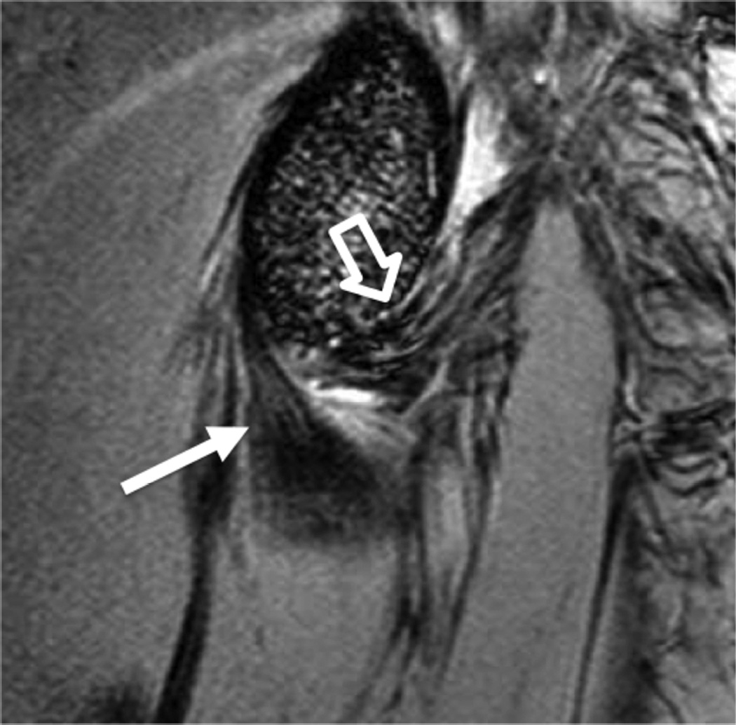
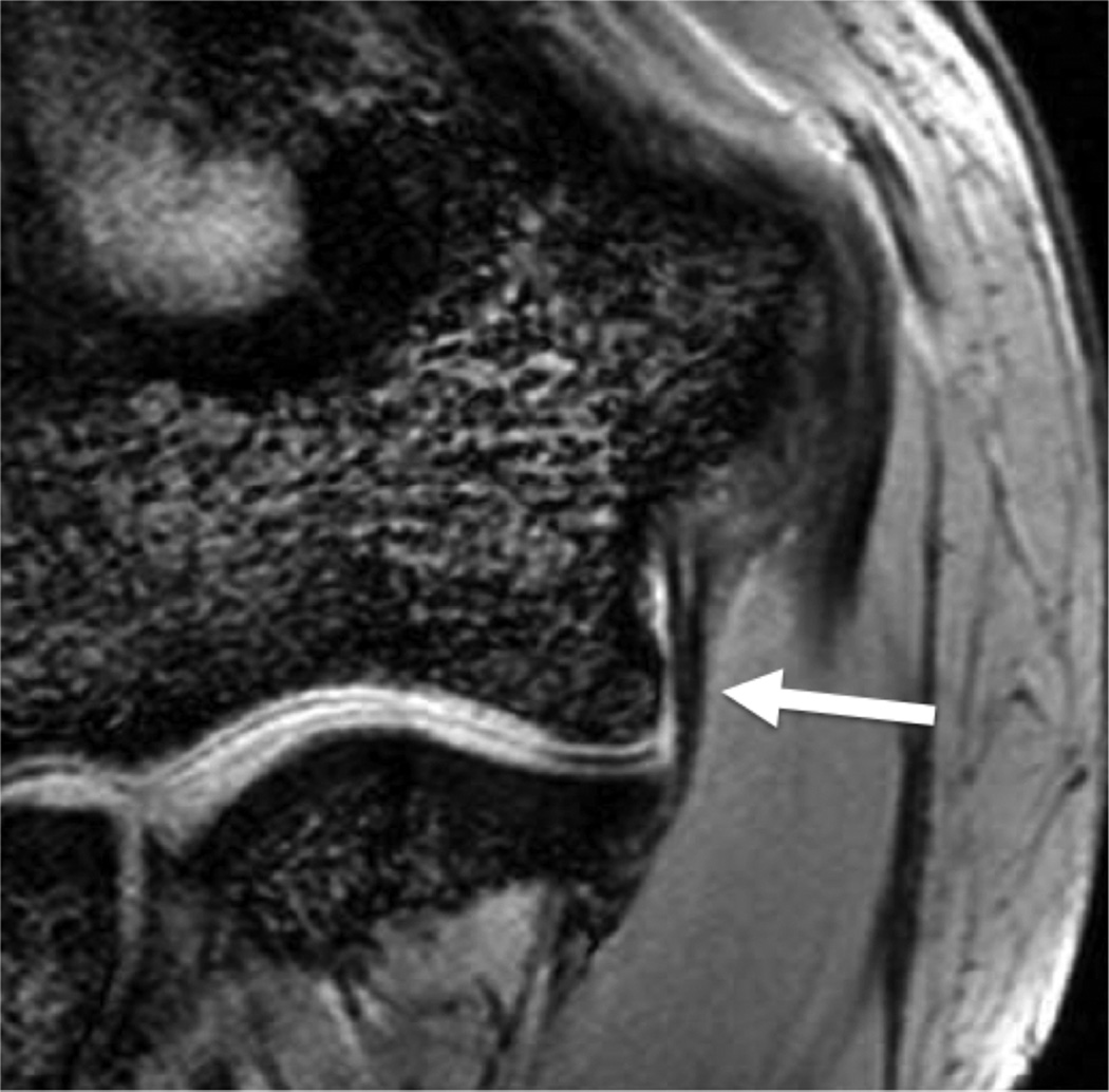
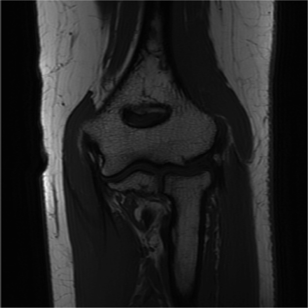
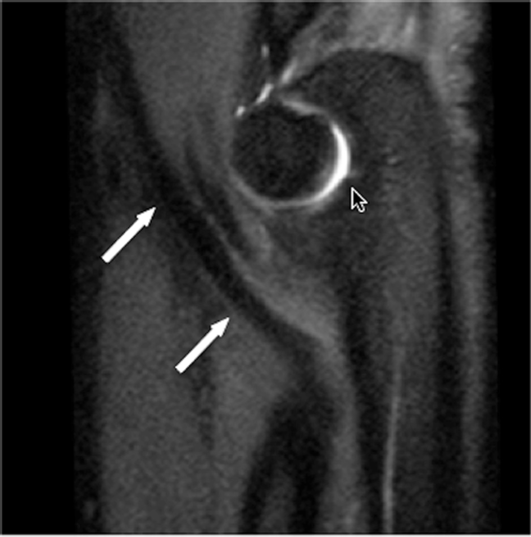
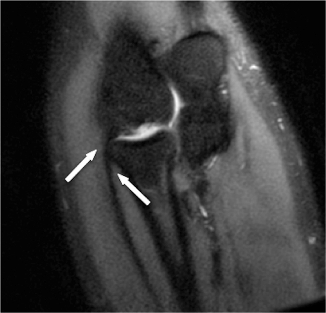
MR imaging at field strengths below 1.5T is becoming less common, but is still frequently used for wrist and elbow imaging. Dedicated low field strength scanners such as the Artoscan (Esaote, Inc) are able to produce intermediate quality images of these joints, and can be more comfortable for the patient. In addition, specialized coils can produce high resolution images, despite the relatively low field strength (Fig 1). Low field MR imaging of the wrist is common in the evaluation of rheumatoid arthritis6,7 and is useful in scoring bony erosions and synovitis. It has also been demonstrated to be useful after wrist trauma8. Examination of the elbow with low field systems is less common than the wrist.
Figure 1.
Sagittal (A) and coronal (B) T2* images of the elbow obtained on a 1.5 T scanner using a 2 inch microscopy coil demonstrating the anterior (arrow) and posterior bands (open arrow) of the medial collateral ligament.
High field imaging
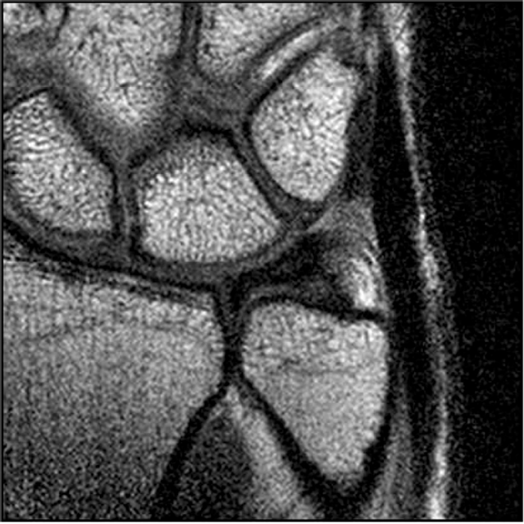
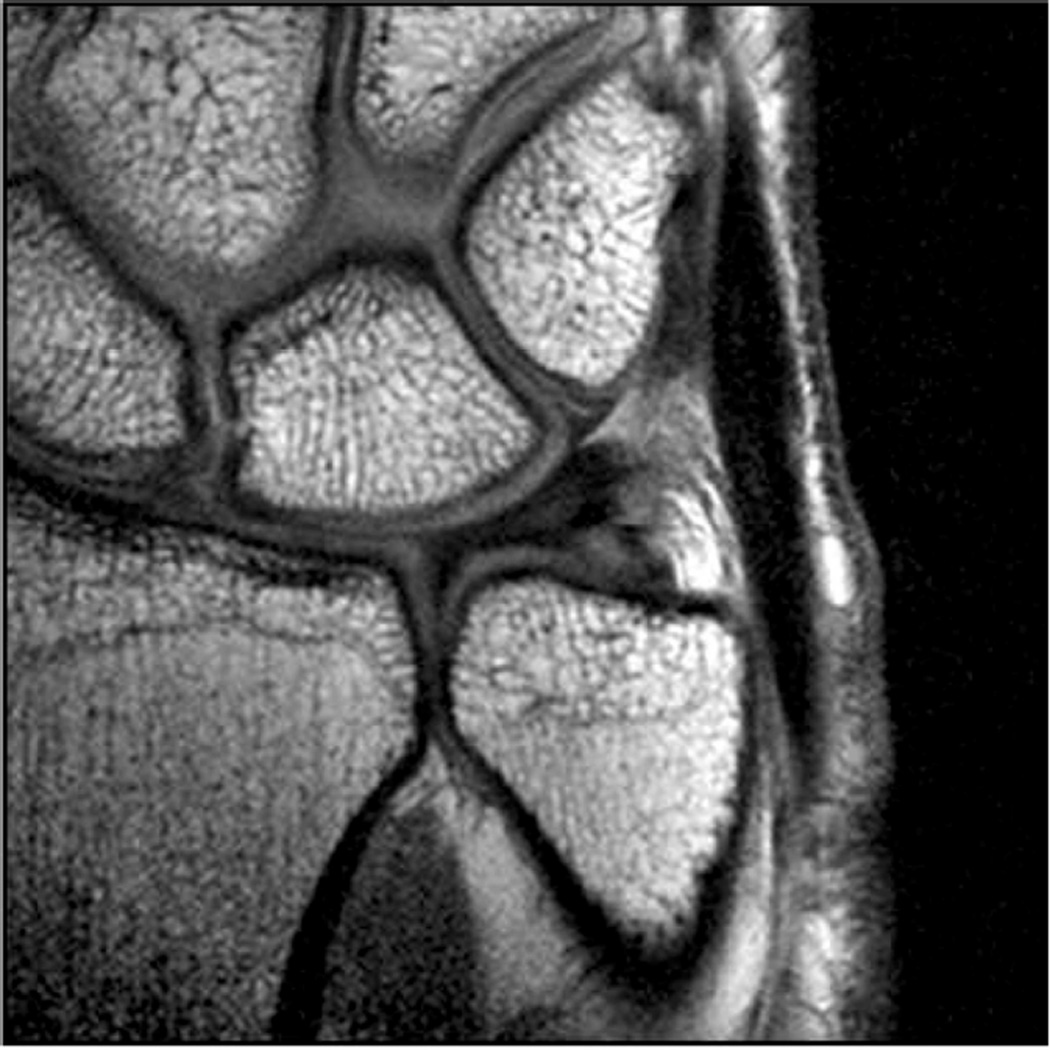
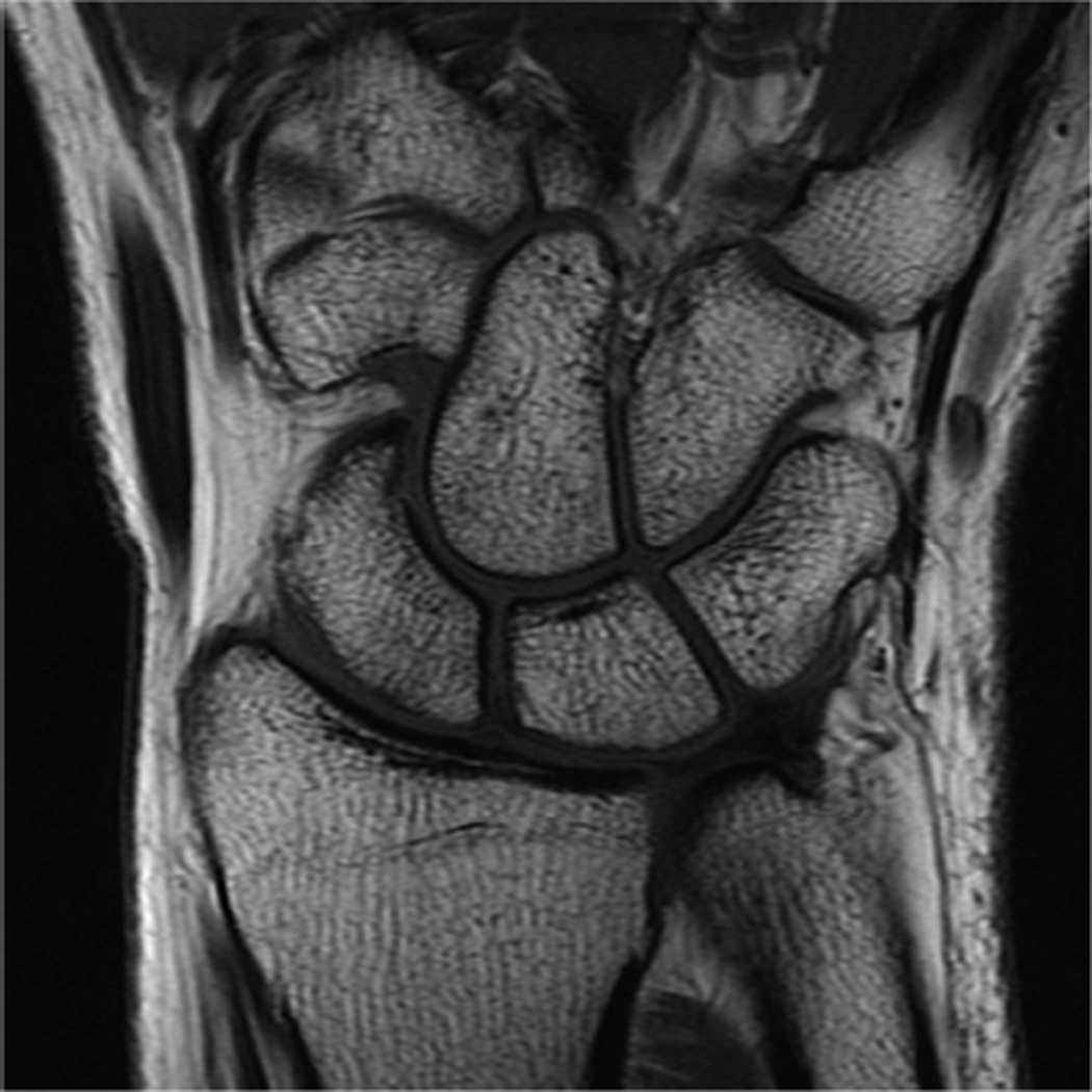
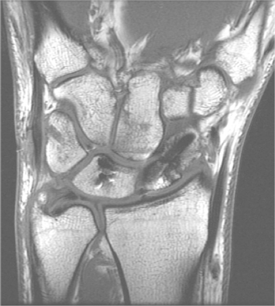
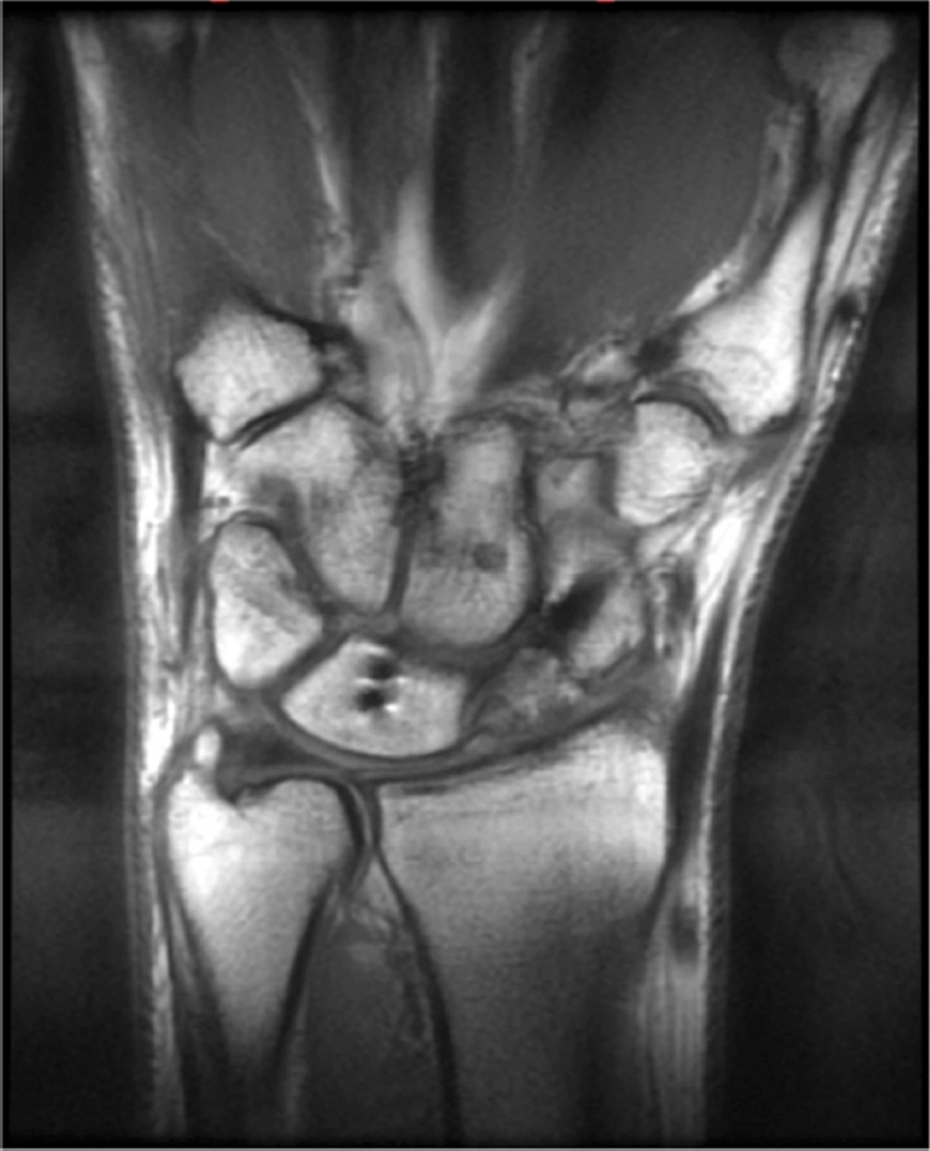
MR imaging of the wrist and elbow is now commonly performed at intermediate field strengths of 1.5T or higher. Imaging at 3.0T has become increasingly common for clinical evaluation, while even higher field systems (7.0T) are being evaluated in the research realm9. While initially used for neurological imaging, numerous studies have confirmed the benefits and abilities of higher field systems in musculoskeletal imaging10–12. In particular, the development of dedicated coils has increased the utility of high-field imaging. The most valuable benefit is an improved signal-to-noise (SNR), which can result in increased image resolution (Fig 2). Additionally, increased SNR affords the opportunity to shorten the examination time. However, with the increase in field strength to 3.0 T or higher, numerous technical factors must be considered to optimize its intrinsically superior imaging capabilities.
Figure 2.
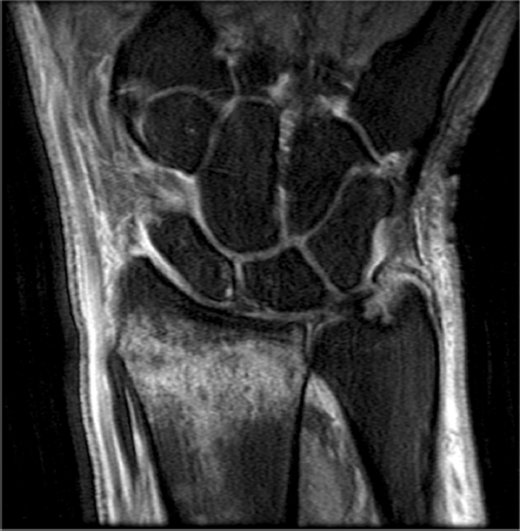
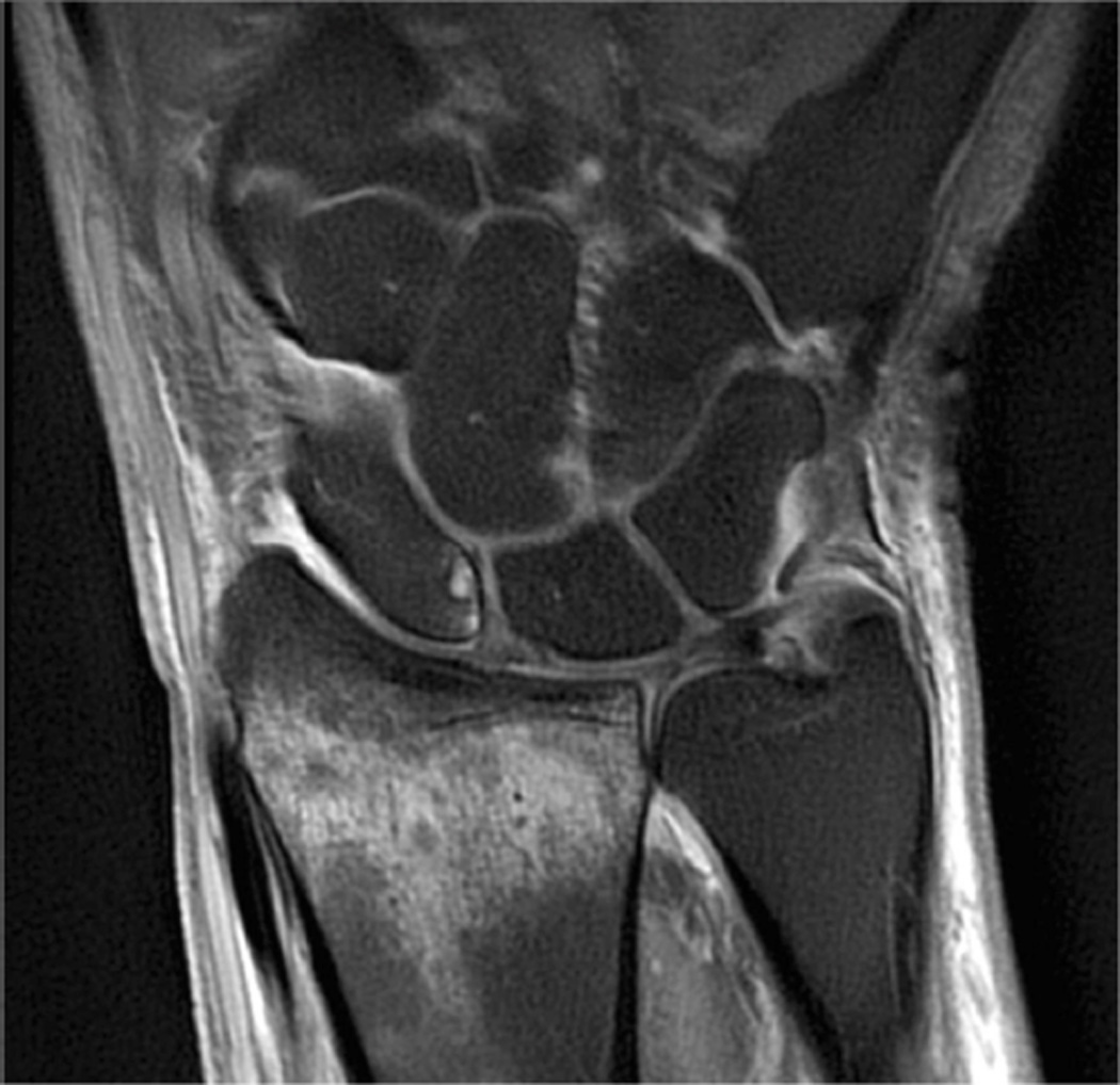
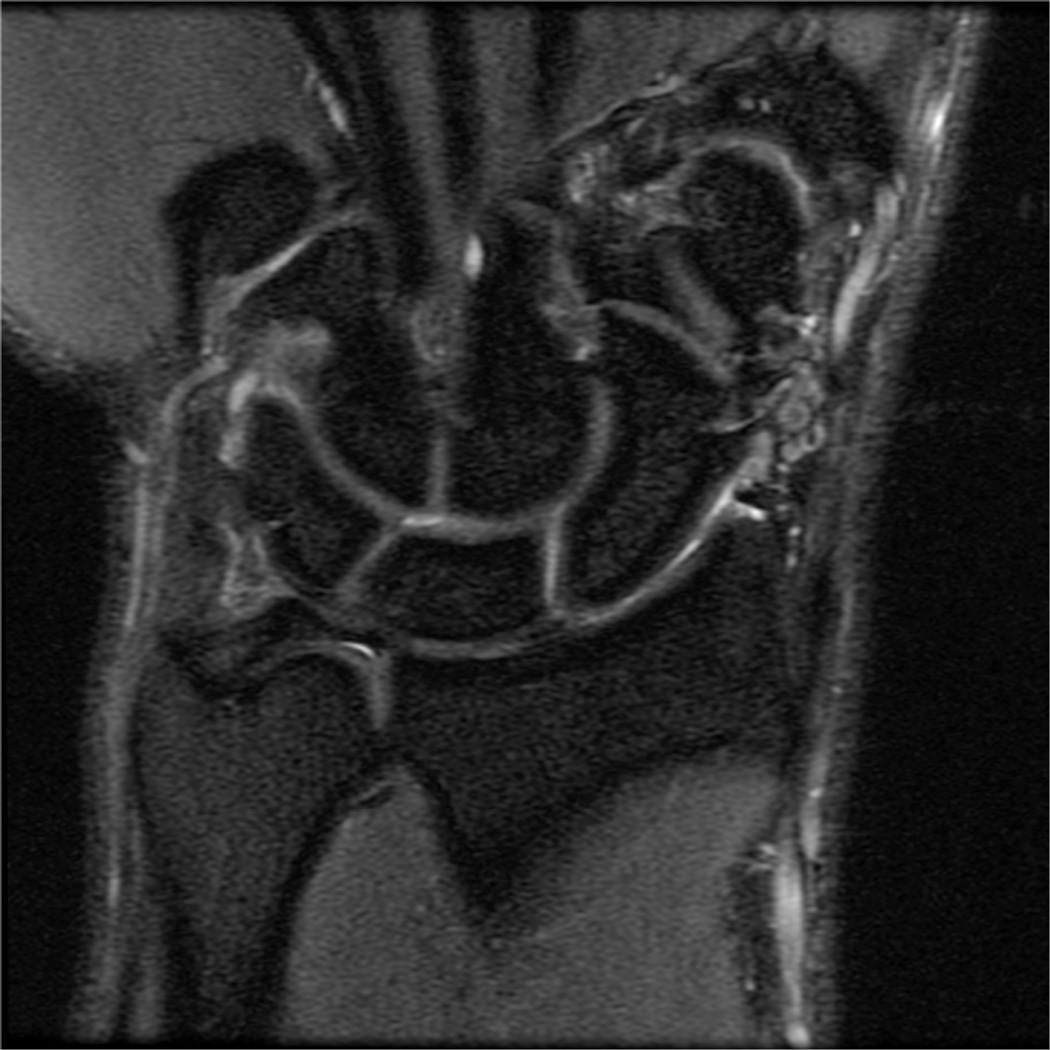
Coronal T1 images of the triangular fibrocartilage of the wrist utilizing a microscopy coil demonstrating low signal-to-noise ratio (SNR) on image A, and improved SNR and image quality on image B, as can be seen with increasing magnetic field strength.
While one would assume that doubling the field strength from 1.5T to 3.0T should result in double the intrinsic SNR, it actually results in slightly less than a two-fold increase because of changes in T1 relaxation times and complexities of coils at higher field strengths. Research measuring changes in relaxation times have shown that T1 relaxation times must be increased by 14–20% when moving from 1.5T to 3.0T11. Increased off-resonance effects may result in higher receiver bandwidth for some sequences, which in turn, reduces SNR.
There are several technical considerations that must be addressed in order to take full advantage of 3.0T and higher field imaging systems. The most prominent issues include chemical shift, fat saturation and radiofrequency power deposition. Chemical shift displacement artifact doubles in the frequency encoding direction when moving from 1.5T to 3.0T. Doubling the receiver bandwidth is one way to resolve this issue. Doubling the bandwidth not only corrects the chemical shift artifact, but may also allow for an increase in the number of slices acquired, decrease metal artifacts, shorten echo times, and reduce echo spacing. On the other hand, doubling the bandwidth decreases the SNR by a factor of √2 because the overall readout window length is shorter.
The doubled chemical shift difference between the fat and water resonance at 3.0T and 1.5T makes fat saturation much easier. The peaks are twice as far apart with a chemical shift of 440 Hz, meaning that the lengths of the fat saturation pulses can be shortened from about 16 msec to 8 msec13. An advantage of this is the ability to acquire more slices at a given TR, bandwidth and slice thickness.
Radiofrequency power deposition is a third technical issue, especially in fast or turbo spin-echo sequences used in musculoskeletal imaging. Radiofrequency power is proportional to the square of the field strength; therefore it will quadruple when field strength is doubled from 1.5T to 3.0T14,15. While the overall deposition is dependent upon the number of radiofrequency pulses and amplitude, using rapid imaging sequences with lower flip angles may minimize the deposition. When examining small volumes and using transmit receive coils, this complication should be diminished, since the radiofrequency power that is deposited is a function of the tissue volume excited15. However, many dedicated wrist and surface coils use the body coil to transmit RF energy and can result in high specific absorption rate (SAR).
It is more advantageous to use a localized transmit/receive RF coil than a body coil transmit; however, if a body coil transmit is used, shortening the examination time or lowering the refocusing pulses would help limit SAR. The FDA limitation for the whole body over a 15-minute period in all patients is 4 W/kg and for extremities over a period of 5 minutes the local SAR limit is 12 W/kg16,17.
The use of 7.0T to image the musculoskeletal system is still in the early stages, and there are many technical problems including SAR, chemical shift, and B1 homogeneity9,18,19. Routine imaging at 7.0T could provide higher SNR, higher resolution, or more rapid imaging. Multichannel coils with parallel transmission capability are under development, which promise to improve image quality and lower SAR.
Phased array coils/parallel imaging
Higher field strength MR imaging systems are being developed to increase signal-to-noise ratio and improve resolution. However, tissue/field interactions often develop due to a higher precession frequency and shorter wavelength, making it difficult to acquire high quality images. Phased array coil technology was originally developed to improve the signal intensity uniformity of MR images obtained using surface coils and high field imaging, while preserving the inherent signal-to-noise ratio (SNR) gain. New methods for encoding the MRI signal are being adopted that fall under the generic name of “parallel imaging.” Parallel imaging methods exploit the spatially-varying sensitivity profiles of the surface coil elements within the array to extend the imaging field of view without adding additional scan time. This strategy allows a net reduction in the amount of time required to obtain the MR image up to a factor related to the number of independent coil channels within the array. Multiple channels are required to process the data independently, and in principle, an eight-channel coil would be able to image eight times as fast, assuming an ideal geometry. However, practical considerations limit image acceleration to values below the theoretical maximum.
The clinical impact of parallel imaging is considerable for the higher field imaging of the wrist and elbow at 3.0T. The use of parallel imaging technology can not only reduce scan time and the number of radiofrequency (RF) pulses required to form an image, but can also be used to shorten the echo time, which proves to be a significant improvement for musculoskeletal imaging. This will be important in limiting the total RF power to regulatory guidelines, particularly for wrist and elbow imaging with body coil transmit at 3.0T. When parallel imaging is employed, image uniformity and SNR are both compromised as scan times are reduced. Innovative phased array coil designs with up to 32 or more channels have been developed to accommodate parallel imaging methods at higher magnetic fields. The newest MR imaging systems are being offered with receiver system capacity for a highly scalable number of individual RF channels. The maximum number of RF channels that can practically be incorporated into the design of clinical MRI systems is controversial.
Positioning and fat suppression
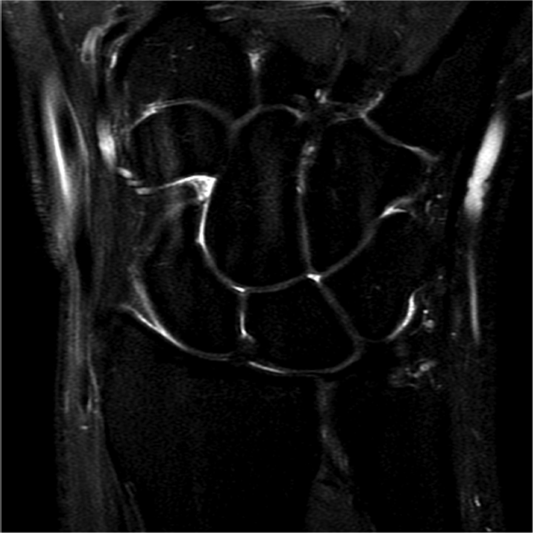
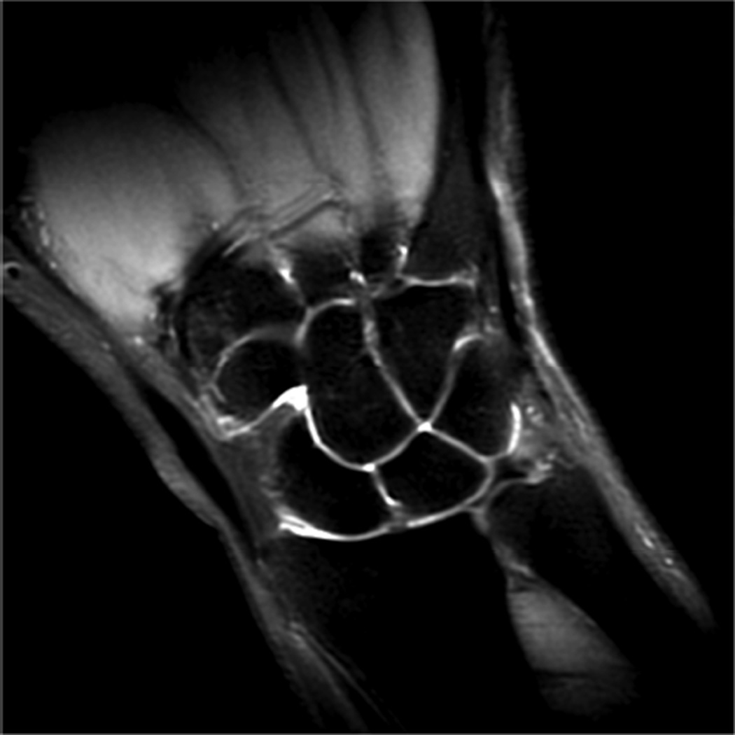
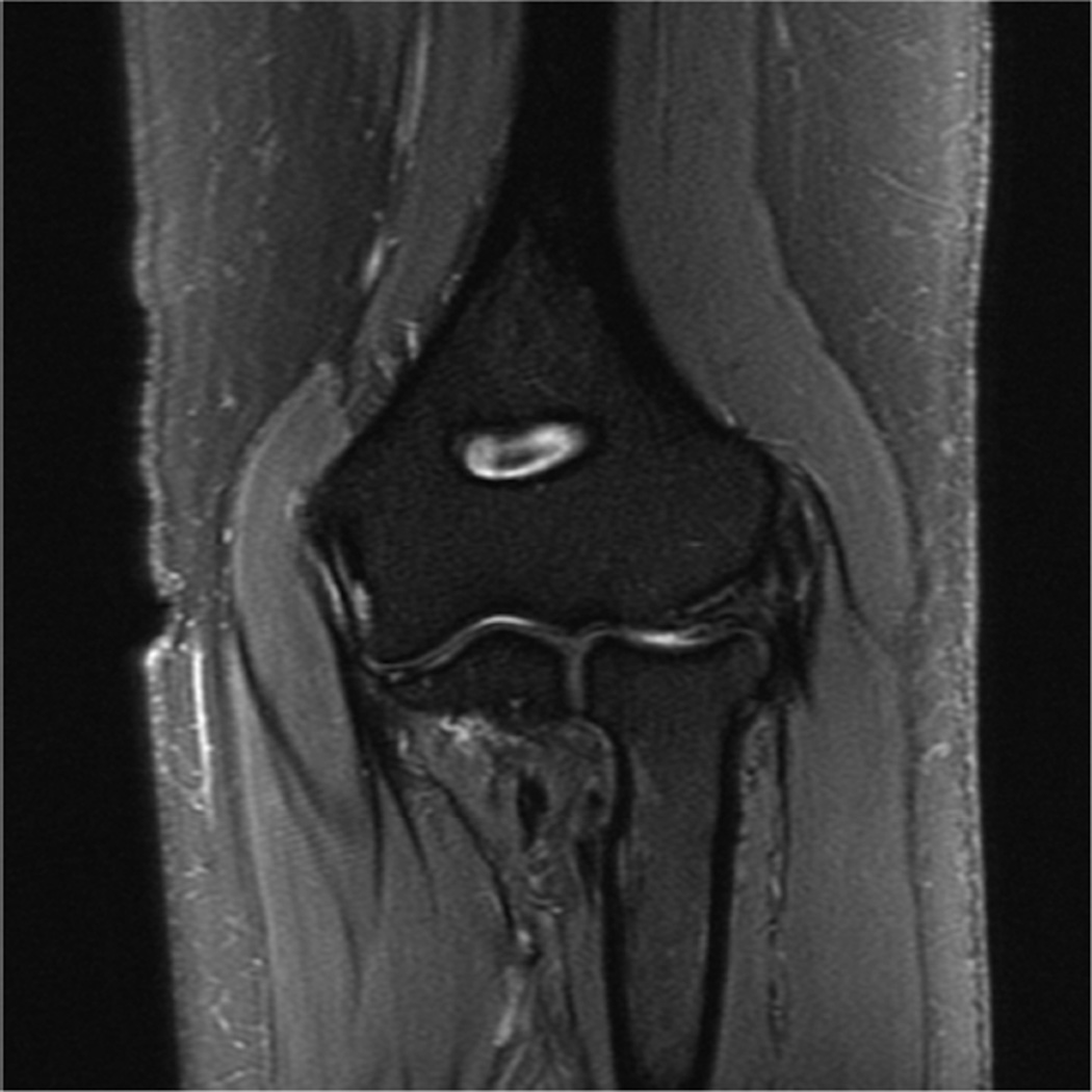
Ideally the body part of interest is placed at the isocenter of the scanner, where magnetic field homogeneity and gradient uniformity is best. However, this can be challenging for wrist and elbow imaging. Placing the wrist or elbow at isocenter usually requires prone positioning with the arm of interest over the subjects head, the so-called “superman” position. This places the anatomy of interest in the best location for imaging, but can be uncomfortable and difficult to maintain for long periods of time, and therefore prone to motion artifact (Fig 3A). Motion artifact can be improved by adding motion-insensitive sequences, such as propeller (Fig 3B), to the protocol20.
Figure 3.
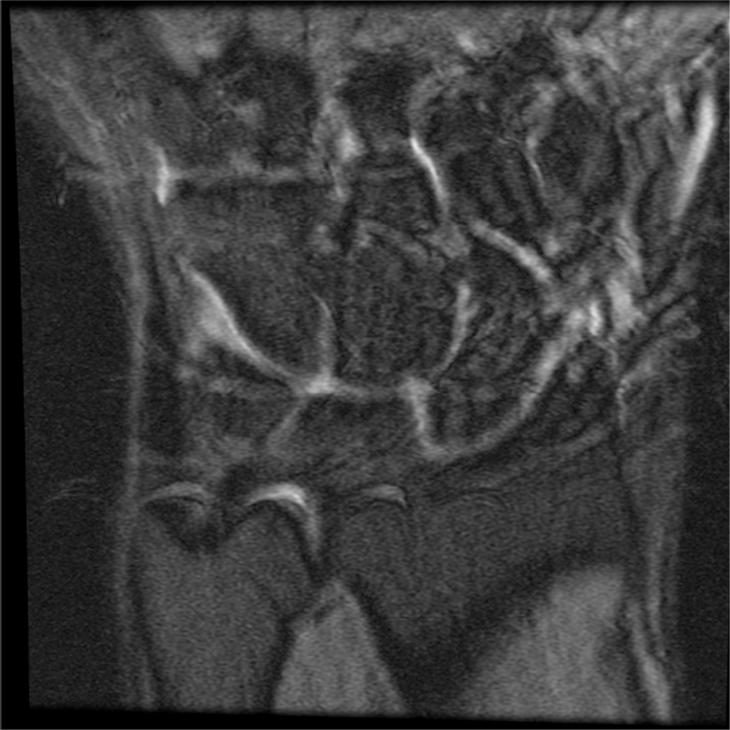
(A) Coronal PD FS of the wrist showing mild motion artifact, which improves using a motion-insensitive sequence - Coronal PD FS Propeller (B).
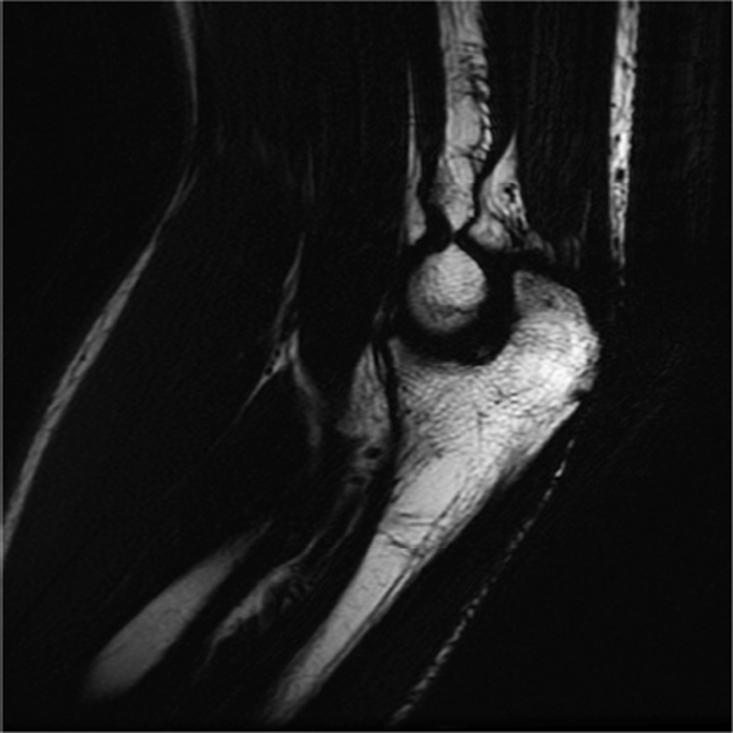
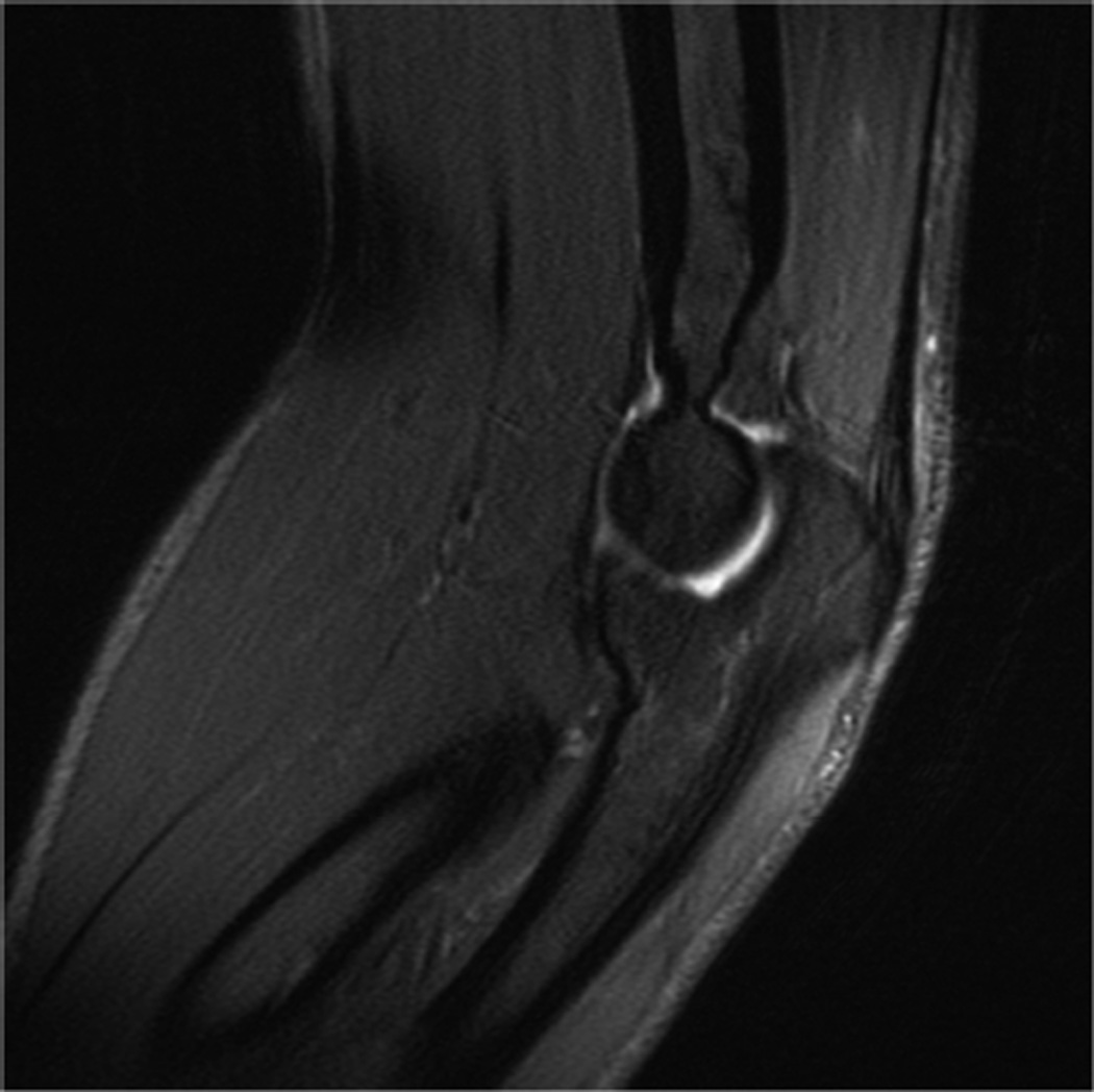
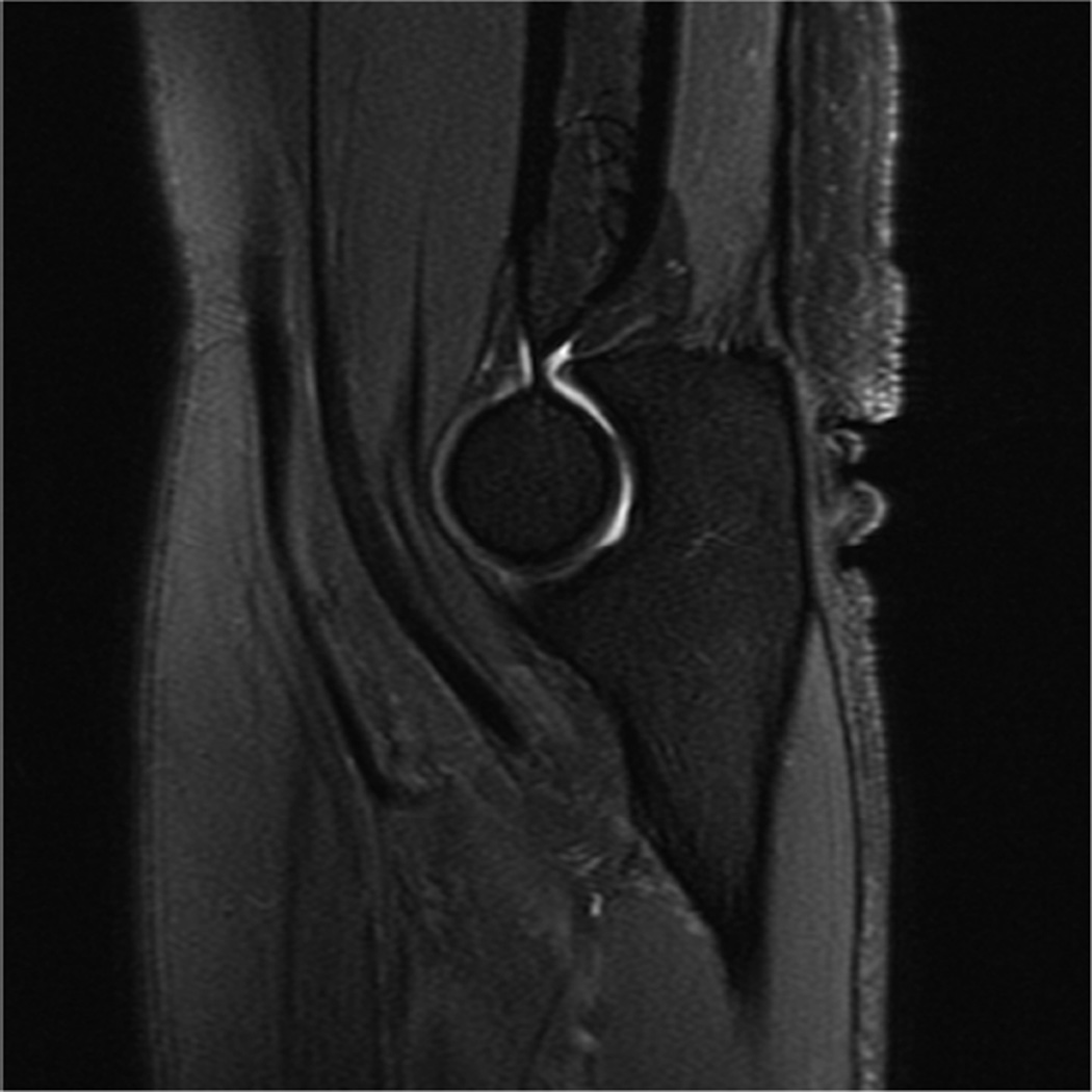
Modern phased-array multichannel coils allow placement of the wrist or elbow by the side of the patient in a supine position, which is more comfortable and less prone to motion. However, this places the anatomy far from the isocenter, and achieving high quality imaging with fat suppression can be difficult (Fig 4A). Use of manual shimming and manual prescan to set the center frequency can often correct this problem (Fig 4B). Use of short Tau inversion recovery for fat suppression or methods of fat/water separation such as IDEAL can also be helpful to obtain quality fat suppressed or fat-water separated images in areas of poor magnetic field homogeneiety21,22.
Figure 4.
Sagittal T2-weighted fat suppressed images of the elbow in a patient with acute trauma. Due to the patient’s trauma, the elbow was positioned near the side of the patient. A) Initial T2-weighted image with failure of fat saturation due to off-resonance. B) Improved fat saturation after manual shim and adjustment of center frequency.
Direct and Indirect MR Arthrography
MR arthrography is an important alternative to conventional MR imaging of the wrist and elbow, particularly in cases where detailed evaluation of cartilage or ligaments is vital. Direct MR arthrography distends the joint compartment allowing for better delineation and visualization between tissues. It also allows for detection of abnormal communication between joint compartments and between extra-articular soft tissues and joint compartments. The drawbacks of direct MR arthrography are that it is invasive, thereby introducing the potential for infection, and exposes the patient to x-rays for procedure guidance.
Indirect MR arthrography is useful in joints that have less capacity for distension, and is less invasive than direct MR arthrography. A disadvantage of indirect MR arthrography is that contrast will be present in all components of the joint, preventing visualization of abnormal communication between joint compartments. In addition, the level of joint enhancement is dependent on joint volume, intra-articular pressure, blood concentration of contrast, inflammation and permeability, synovial area and time delay post contrast injection23,24. Despite the drawbacks of both direct and indirect MR arthrography, these techniques have proven useful in the evaluation of most joints including the elbow and wrist25–27.
3.0T MR Imaging Protocols
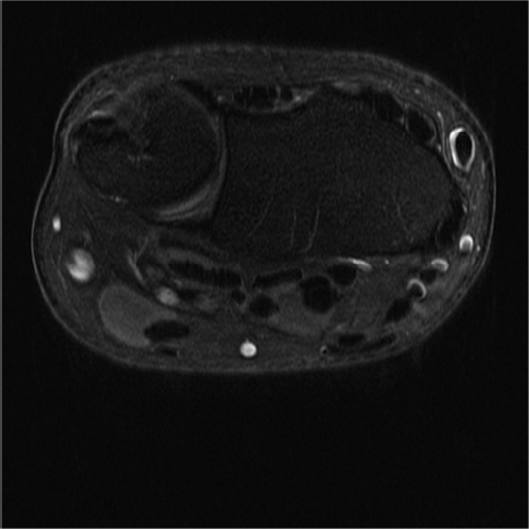
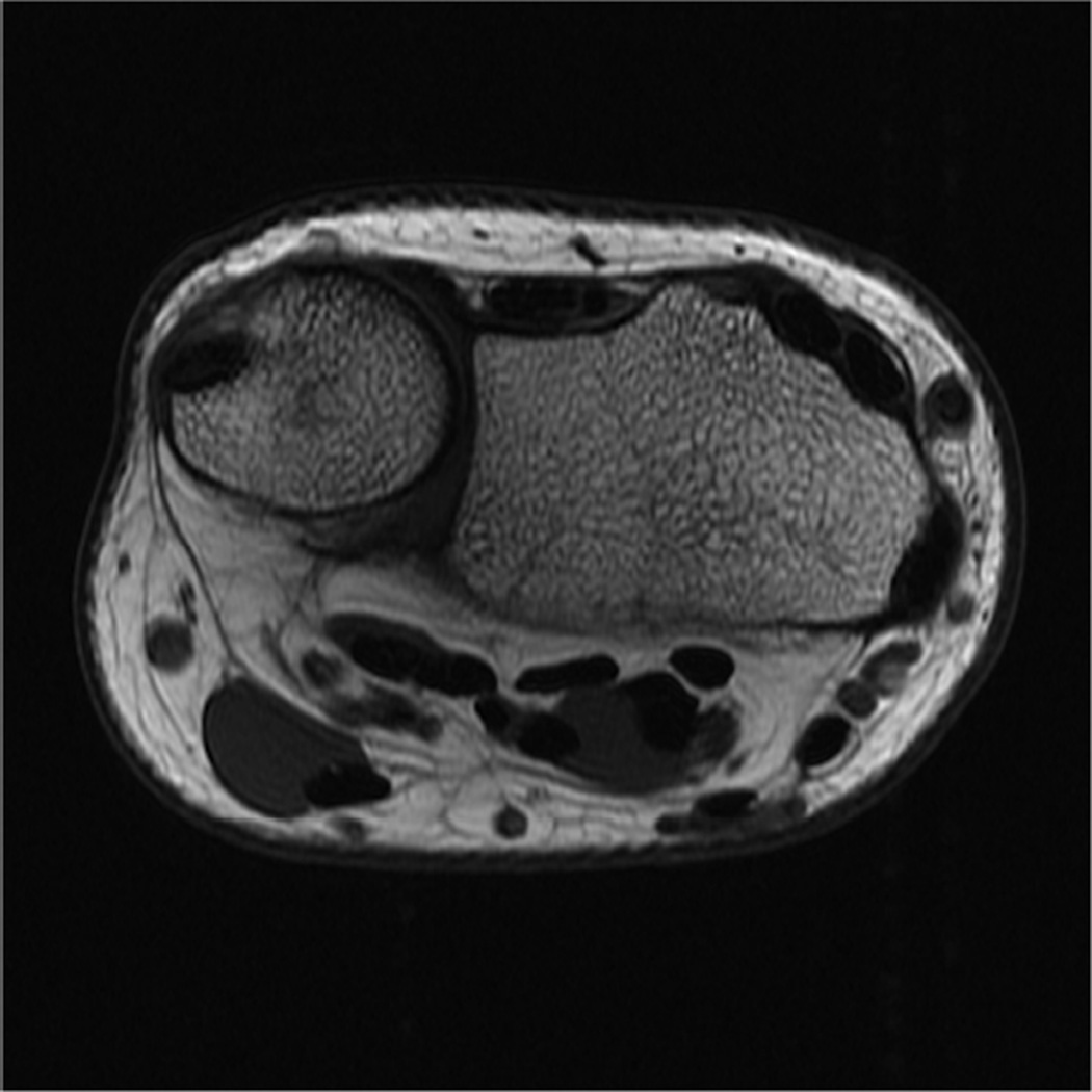
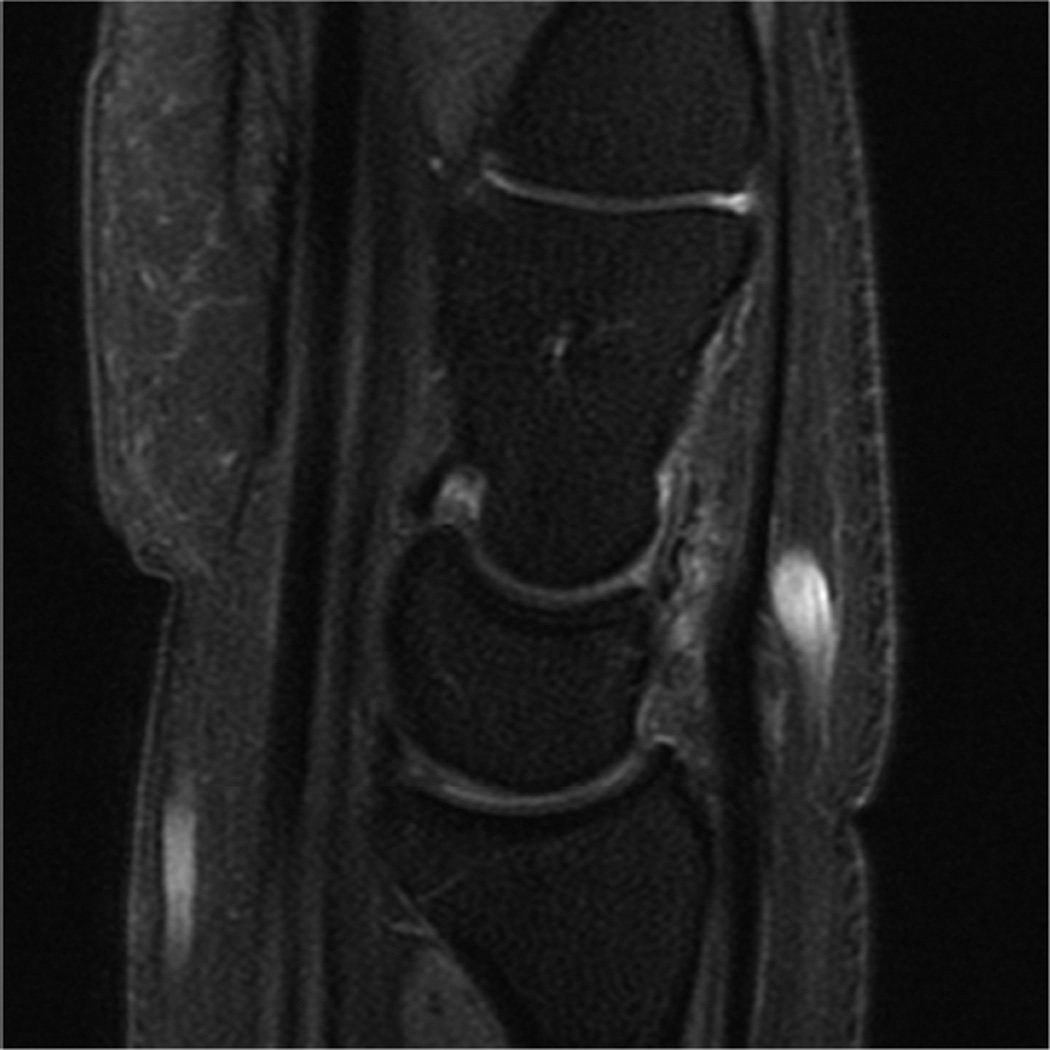
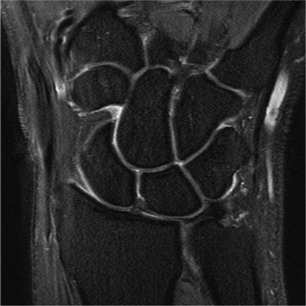
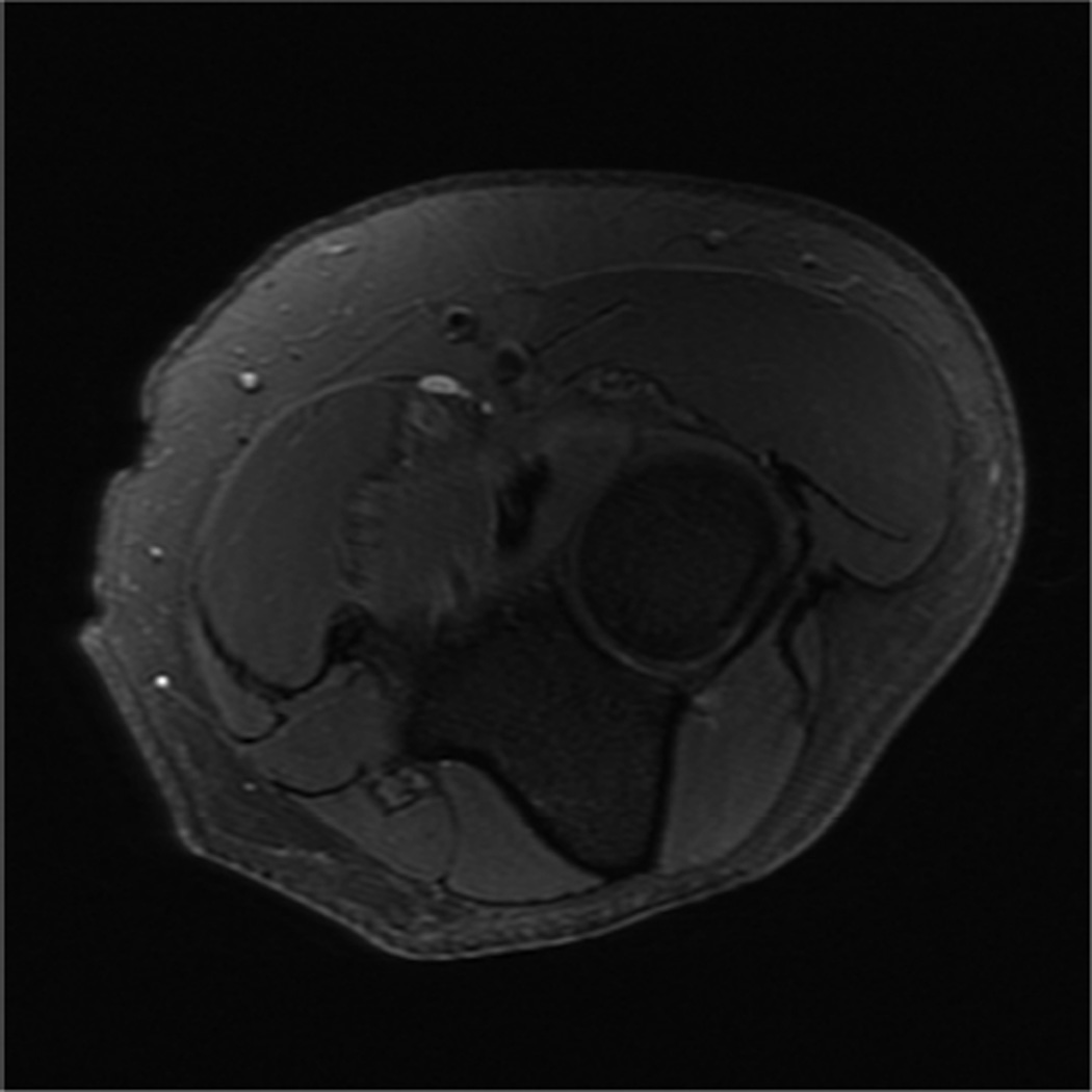
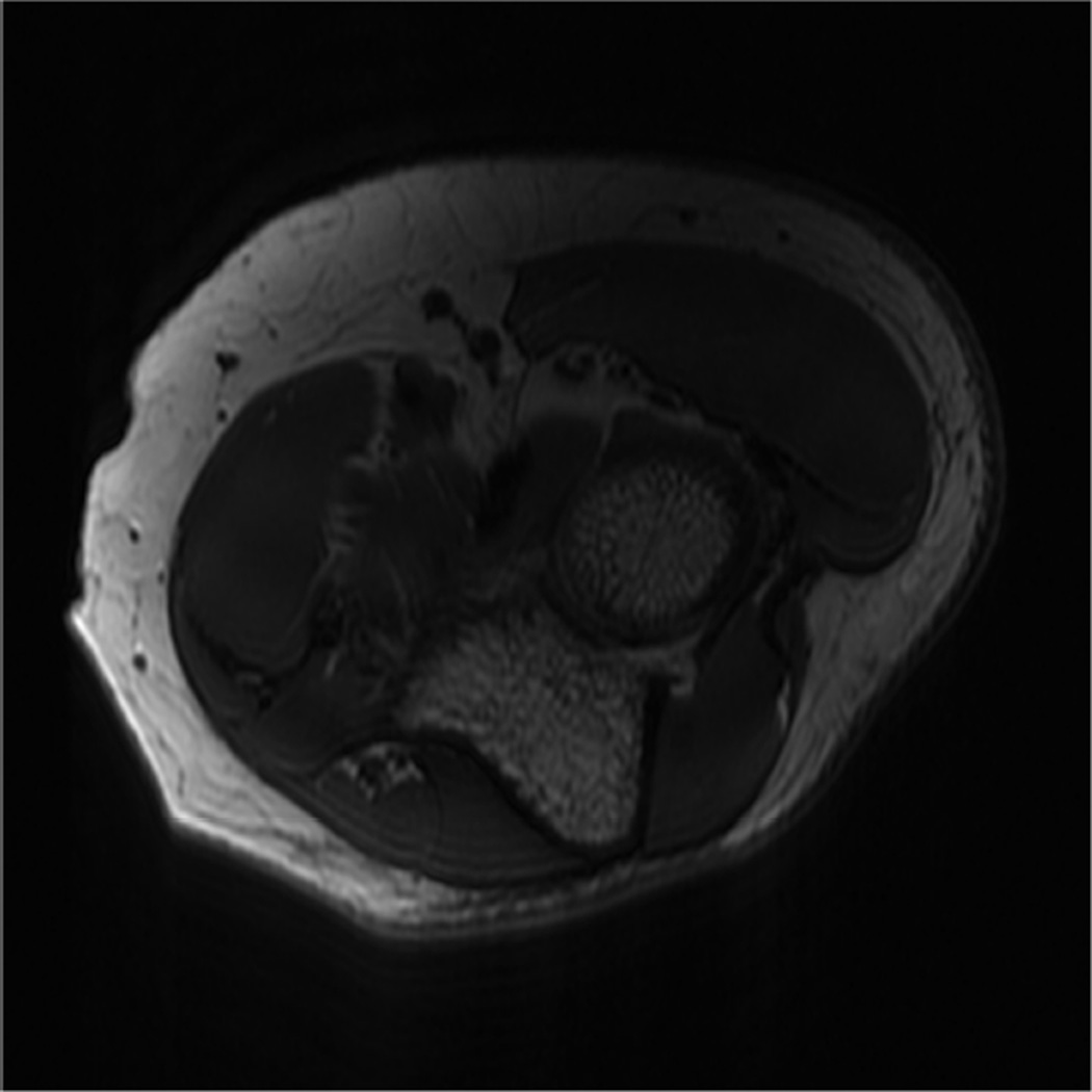
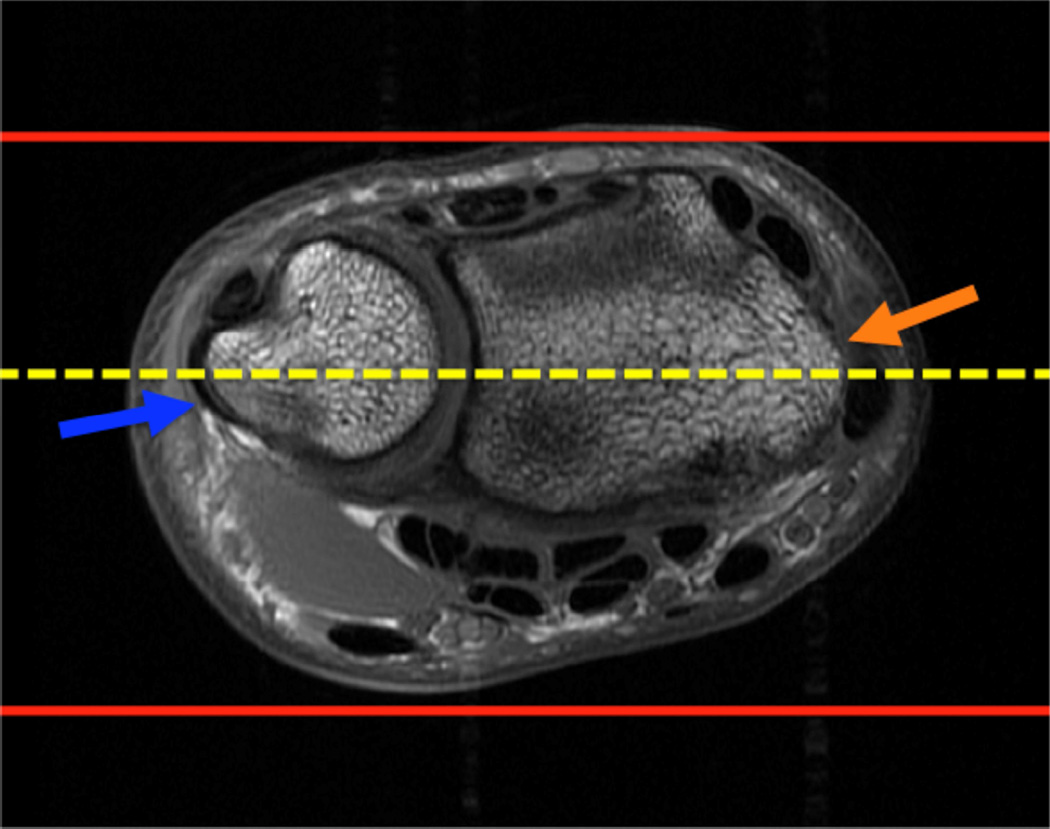
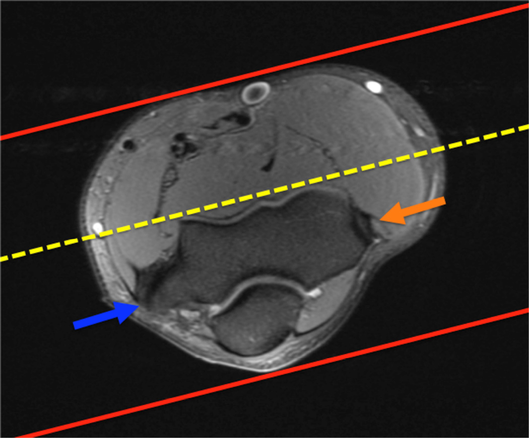
Example 3T imaging protocols are included for the wrist (Table 1, Fig 5) and the elbow (Table 2, Fig 6). These protocols are relatively long in total scan time by modern standards but include good coverage of the anatomy and high signal-to-noise and resolution. The important principle is to cover the joint in multiple planes and with multiple different tissue contrasts. Coronal images of the wrist are obtained by acquiring oblique slices oriented parallel to the ulnar and radial styloids (Fig 7). Coronal images of the elbow are prescribed in plane with a line drawn along the anterior margin of the humerus at the level of the medial and lateral condyles (Fig 8).
Table 1.
Suggested MRI protocol for wrist imaging at 3T (Wrist Coil)
| Sequence | FOV (cm) |
TR | TE | Slice Thickness (mm)* |
Matrix |
|---|---|---|---|---|---|
| Cor T2 FS | 8 | 5500 | 55 | 2.0 | 416×224 |
| Ax T2 FS | 8 | 5000 | 55 | 2.8 | 416×224 |
| Cor PD FS | 8 | 4000 | 35 | 2.0 | 384×192 |
| Cor T1 | 8 | 750 | 20 | 2.0 | 416×192 |
| Ax T1 | 8 | 750 | 20 | 2.8 | 416×192 |
| Sag PD FS | 8 | 4000 | 40 | 2.5 | 320×224 |
| Cor CUBE Flex | 12 | 2000 | 25 | 2 | 224×224 |
No interslice gap is utilized on any sequences, allowing for contiguous images.
Figure 5.
Images from the 3T wrist protocol shown in Table 2, acquired in a patient with the 8-channel phased-array wrist coil. A) Axial proton-density weighted (PD) with fat saturation (FS) B) Axial T1-weighted C) Sagittal PD FS D) Coronal PD FS E) Coronal T1-weighted F) Coronal T2-weighted and G) Coronal Cube Flex.
Table 2.
Suggested MRI protocol for elbow imaging at 3T
| Sequence | FOV (cm) |
TR | TE | Slice Thickness (mm)* |
Matrix |
|---|---|---|---|---|---|
| Cor T1 | 14 | 750 | 17 | 2.0 | 384×192 |
| Cor T2 FS | 14 | 5000 | 55 | 2.0 | 384×224 |
| Ax T1 | 14 | 750 | 17 | 3.0 | 384×192 |
| Ax PD FS | 14 | 4600 | 34 | 3.0 | 384×224 |
| Sag T1 | 14 | 750 | 17 | 2.5 | 384×192 |
| Sag T2 FS | 14 | 4500 | 55 | 2.5 | 384×224 |
No interslice gap is utilized on any sequences, allowing for contiguous images.
Figure 6.
Images from the 3T elbow protocol shown in Table 3, acquired in a patient with the 16-channel phased array flex coil. A) Coronal T1-weighted B) Coronal proton-density-weighted (PD) with fat saturation (FS) C) Axial PD FS D) Axial T1-weighted E) Sagittal PD FS F) Sagittal T1- weighted.
Figure 7.
Prescription for coronal images of the wrist: Select a plane (yellow line) parallel to the ulnar styloid (blue arrow) and radial styloid (orange arrow). The field of view extends to the volar and dorsal skin surfaces (red lines).
Figure 8.
Prescription for coronal images of the elbow: Select a plane along the anterior aspect of the humerus (yellow line) at the level of the medial (blue arrow) and lateral (orange arrow) condyles. The field of view extends to the volar and dorsal skin surfaces (red lines).
Isotropic imaging
MRI of the musculoskeletal system is conventionally performed with two-dimensional (2D) multi-slice acquisitions. Turbo spin-echo (TSE) or fast spin-echo (FSE) acquisitions are commonly used, as they provide excellent visualization of anatomy and pathology, including meniscal tears28,29, ligamentous injury30 and cartilage damage31. The drawback of 2D-FSE is that the voxels obtained are anisotropic. This results in relatively thick slices in comparison to the in-plane resolution, leading to partial volume artifact31. Anisotropic voxels preclude the images from being reformatted into various oblique planes. As a result of the slice gaps, cartilage volume and other important structure quantifications cannot be performed accurately.
The recent introduction of an isotropic three-dimensional (3D) imaging technique by various manufacturers has shown much promise in visualization of anatomy and pathology as well as in cartilage quantification (Table 3). Imaging of small joints such as the wrist and elbow can benefit considerably from these methods. Isotropic imaging eliminates slice gaps and reduces partial-volume artifact by obtaining thin contiguous slices32,33. The use of isotropic voxels allows images to be reformatted retrospectively into arbitrary planes in order to better visualize oblique anatomy (Fig 9)34. A significant decrease in scan time results as reformats can be manipulated from only one acquisition, as opposed to the multi-plane acquisitions necessary with 2D-FSE. On the other hand, 3D-FSE scans can be limited by blurring, although extended echo trains are making this technique more feasible. While still under development, isotropic imaging of the wrist and elbow shows promising results.
Table 3.
Chart displaying sequences from various manufacturers.
| 3D-Fast Spin Echo | Steady-State Free-Precession | Gradient Echo | |
|---|---|---|---|
| General Electric | CUBE | GRASS | SPGR |
| Siemens | SPACE | FISP | FLASH |
| Philips | VISTA | FFE | T1 FFE |
The names of 3D-Fast Spin Echo, Steady-State Free-Precession and Gradient Echo sequences listed by manufacturer.
Figure 9.
Images of the elbow in a 21-year-old healthy female volunteer showing the ability of the 3D-FSE (TR/TE, 3000/35) imaging technique to visualize obliquely oriented structures in the elbow. A. Oblique axial reformat illustrating the lateral ulnar collateral ligament (arrows), B. Oblique sagittal reformat depicting the full length of the biceps tendon as well as the insertion on the same image (arrows), C. Oblique coronal reformat illustrating the common flexor origin and the tendons that originate from it (arrows).
Orthopedic hardware imaging
Metallic implants are increasingly common in the aging population. Although joint replacements are uncommon in the wrist and elbow, metallic fracture fixation hardware is frequently encountered. Computed tomography (CT) is useful for post-operative patient monitoring and for evaluating painful implants. CT, however, results in beam hardening artifacts and is insensitive to marrow edema. MR imaging has shown the most promising results in imaging orthopedic hardware as it allows for cross sectional imaging and flexible soft-tissue contrast. That said, MR imaging is also not ideal, as it suffers from imperfect corrections and susceptibility induced artifacts and signal voids. There are several factors that must be considered in order to optimize MRI for imaging around orthopedic hardware.
Simple modifications can be made to improve MR imaging around metal. For instance, gradient-echo imaging of soft-tissue adjacent to metal is nearly impossible given the local field inhomogeneity resulting in rapid dephasing and corresponding signal voids. Fast or turbo spin-echo imaging with maximum receiver bandwidth is the preferred technique, but spatially dependent artifacts are still present35.
Several alternative techniques have been proposed to improve MR imaging around metal. When looking for homogenous fat suppression around the hardware, Iterative Decomposition of water and fat with Echo Asymmetry and Least-squares estimation (IDEAL) fast spin-echo imaging has proven more reliable than fat saturation, as slowly to moderately varying field inhomogeneity can be corrected in the reconstruction36–38. IDEAL is a Dixon-based method for separating water and fat that allows for water-only and fat-only images to be obtained in the presence of the inhomogeneity caused by the hardware. In addition, T1-weighted images after gadolinium with water/fat separation can be acquired. As it requires three acquisitions, IDEAL results in an increase in exam time; however, this can be offset with the use of parallel imaging or protocol modification.
Prepolarized MRI has shown to be a promising technique to reduce artifacts around hardware39,40. This new, inexpensive approach to MRI consists of two electromagnets; one is a homogenous low-field readout magnet, while the second is a high-field polarizing magnet that can be somewhat inhomogeneous. This system creates two dynamic magnetic fields: a polarizing field, which creates the sample magnetization, and a readout field, which determines the acquisition frequency. As opposed to the traditional single static magnetic field, these dual dynamic magnetic fields provide the advantage of a low field read-out that results in shift reduction of about 30 fold41. Prepolarized MR imaging, although helpful in resolving several of the issues that arise when imaging around metal, is not yet clinically available.
Two innovative techniques in the area of multi-spectral MRI have been developed to improve imaging around metal. Slice Encoding for Metal Artifact Correction (SEMAC) and Multiple-Acquisition with Variable Resonances Image Combination (MAVRIC) have exhibited great potential in correcting metal artifact. The SEMAC technique is achieved by combining view-angle tilting for correction of in-plane artifacts42 with additional phase encoding steps in the slice-dimension to fully resolve slice selective distortions43.
The MAVRIC technique decreases encoding errors by employing several spectrally unique 3D acquisitions. MAVRIC collects several acquisitions at different frequencies to construct an image of the whole implant region. Since MAVRIC does not utilize slice or slab selection gradients, the spins within a MAVRIC sub image experience bandwidths determined only by the spectral properties of the applied RF pulses. The Gaussian refocusing pulses, applied with slight overlap between adjacent sub images, used in MAVRIC produce a flat sum of squares (SOS) spectral response, which allow construction of the composite MAVRIC image44.
While artifact reduction is quite noticeable, minor residual artifacts are still present in both SEMAC and MAVRIC techniques. These artifacts result from using different RF pulses and spectral properties as well as a slice-selective gradient in SEMAC. Both techniques have demonstrated compatibility with partial-Fourier techniques and autocalibrated parallel imaging to decrease exam time45,46. Although still primarily in the research stage, both SEMAC and MAVRIC allow visualization of anatomy in close proximity to metallic implants with significantly decreased artifact at reasonable exam times (Fig 10).
Figure 10.
Coronal T1 (A) and coronal PD MAVRIC (B) images show screw-fixation of a scaphoid waist fracture. Image B offers improved visualization of the proximal pole of the scaphoid, which is particularly important given the clinical concern for osteonecrosis.
Diffusion Imaging
Diffusion-weighted imaging is increasing in popularity for body and musculoskeletal applications of MRI. This method has shown promise in the wrist to evaluate synovitis and bone erosions in rheumatoid arthritis47. It has also been recently used to investigate ulnar neuropathy at the elbow joint48. Diffusion-weighted imaging and diffusion tensor imaging are also used to evaluate articular cartilage49.
uTE imaging
Ultrashort TE (uTE) imaging of the wrist and elbow shows promise in evaluation of structures that are difficult to assess on conventional MRI due to short T2 relaxation times. While tissues such as the liver and white matter have long T2 values, short T2 values ranging from hundreds of microseconds to tens of milliseconds have been recorded in ligaments, tendons, menisci, cortical bone and periosteum50. uTE imaging sequences utilize TEs that are 20–50 times shorter than those utilized in conventional imaging sequences in order to detect signal changes from tissues with intrinsically short T2s51–53. Through this method, uTE is able to acquire a high signal from tissues that would typically produce little to no signal such as the triangular fibrocartilage (TFC), ligamentous entheses, and trabecular bone54. It must be noted, however, that scan times can be considerable and slice selection can be challenging. Despite these drawbacks, uTE imaging technology provides a new approach with considerable imaging potential for the wrist and elbow.
T2 and T1rho Mapping
T2 relaxation time changes obtained with spin-echo or fast spin-echo MRI can be quantified by using a number of T2 mapping methods. In the wrist, T2 mapping has been used to evaluate the collagen matrix status of the TFC to detect early degeneration55. T2 relaxation time mapping is also useful to evaluate the collagen status of the articular cartilage56, although the elbow and wrist are less commonly studied. Median nerve signal is also evaluated with T2 mapping57 in the assessment of carpal tunnel syndrome. In the elbow, T2 mapping may be done to evaluate cartilage on the capitellum or trochlea58.
T1rho imaging, or spin-lattice relaxation in the rotating frame, has been demonstrated to be effective in visualizing proteoglycan depletion in cartilage that is associated with early osteoarthritis59,60. In the wrist, T1rho imaging was recently studied to evaluate degeneration of the TFC55.
Imaging of Wrist Motion
MR imaging of motion in the wrist can be done with rapid acquisition times in a single plane using real-time MRI61. Alternatively, repetitive motion cycles can be used to acquire three-dimensional data about the motion of the carpal bones62. Cine phase-contrast MRI can also be used to determine joint motion and velocity of the carpal bones from repetitive motions in the wrist63. In the elbow, Cine phase-contrast MR has been used to evaluate muscle motion and contraction patterns during elbow flexion64.
Conclusion
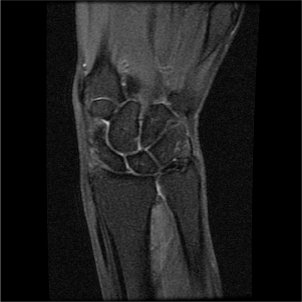
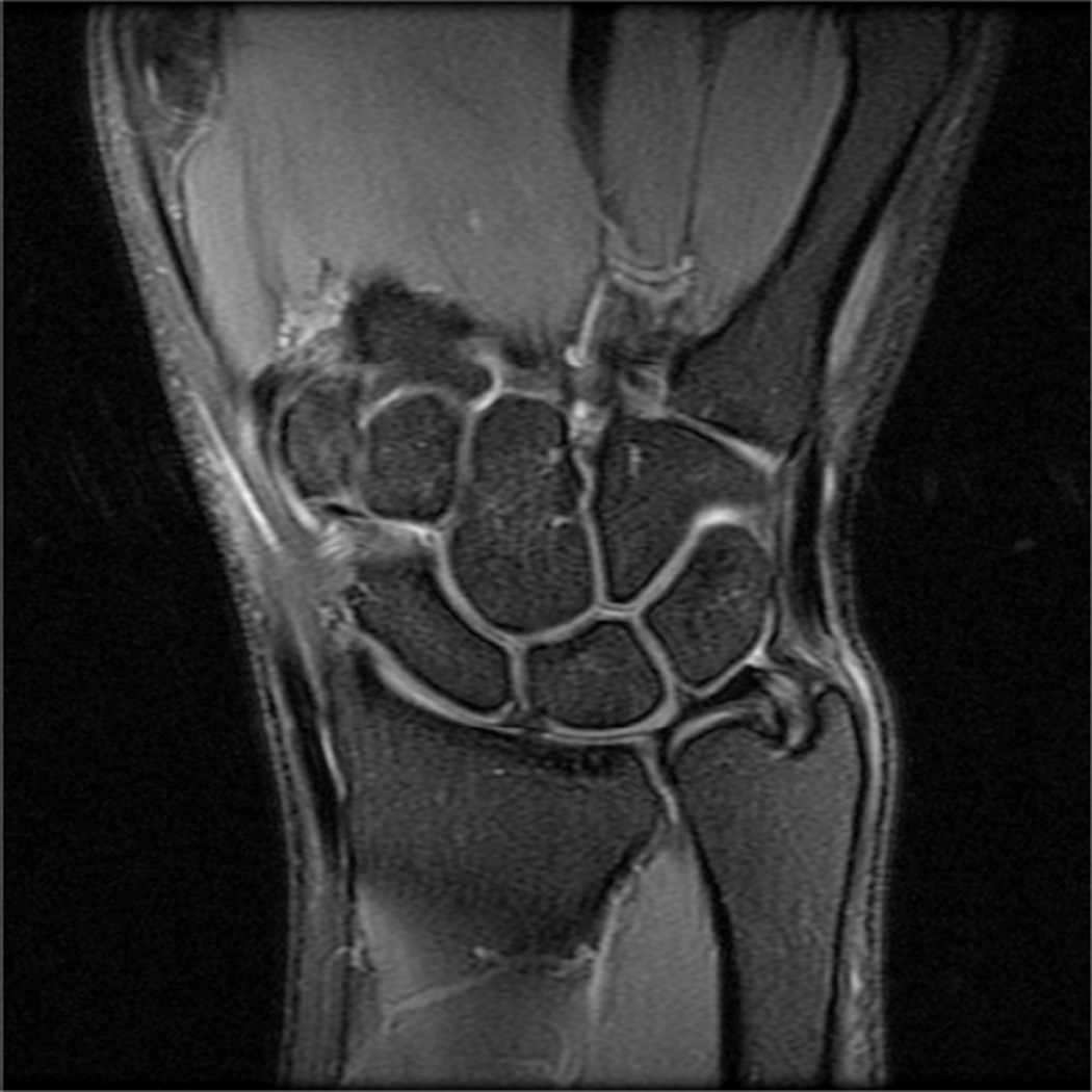
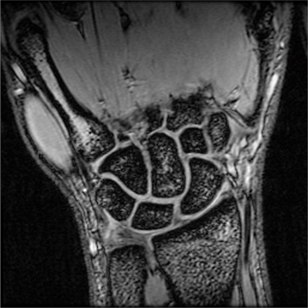
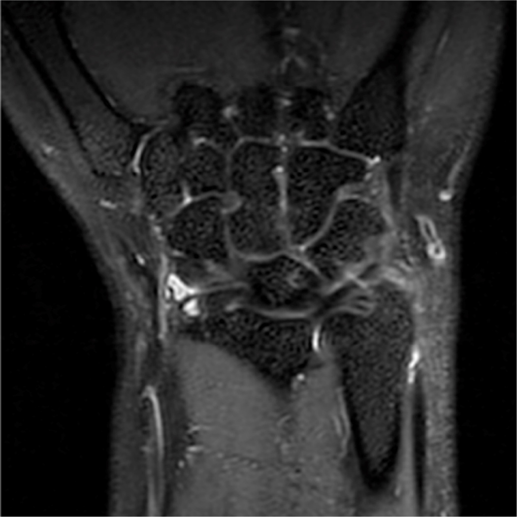
MR imaging has long been established as the preferred modality for evaluating the wrist and elbow. Technical advances in coil technology and high-field scanners have improved resolution, imaging speed, and image quality. Imaging protocols should be adjusted to take advantage of advances in MR hardware and software (Fig. 11) to achieve high quality exams. Newer quantitative methods such as T1rho and T2 mapping, and uTE imaging are promising techniques for evaluating earlier stages of pathology in the soft tissues.
Figure 11.
Representative images of not recommended and recommended MR imaging protocols. Low-resolution not recommended (A) coronal image of the wrist using a 16 cm FOV and 224×128 matrix, 3 mm slice thickness. High-resolution recommended protocol (B) using a 10 cm FOV, 384×192 matrix and 2 mm slice thickness. Coronal 3D gradient echo acquisition (C) is inferior for bone marrow lesions and ligament tears and not recommended compared with newer 3D spin-echo based methods such as 3D FSE Cube (D). Uncomfortable positioning of the joint can lead to subject discomfort and motion (E), which can be corrected with repositioning the joint in a more comfortable location (F).
KEY POINTS.
Positioning of the subject near isocenter of the scanner results in the best image quality in terms of artifacts and fat suppression
High field imaging (> 1.5T) with multi-channel phased array coils results in the best anatomic and contrast resolution
New methods for motion compensation, imaging around metal, and evaluation of cartilage are becoming more widely available.
Acknowledgments
The authors, and research, in this article are supported by NIH EB002524, NIH K24062068, GE Healthcare, Wrist and Elbow Musculoskeletal MRI – Technical Considerations.
Footnotes
Publisher's Disclaimer: This is a PDF file of an unedited manuscript that has been accepted for publication. As a service to our customers we are providing this early version of the manuscript. The manuscript will undergo copyediting, typesetting, and review of the resulting proof before it is published in its final citable form. Please note that during the production process errors may be discovered which could affect the content, and all legal disclaimers that apply to the journal pertain.
References
- 1.Ahn JM, El-Khoury GY. Role of magnetic resonance imaging in musculoskeletal trauma. Top Magn Reson Imaging. 2007;18:155–168. doi: 10.1097/RMR.0b013e318093e670. [DOI] [PubMed] [Google Scholar]
- 2.Gold GE, Hargreaves BA, Beaulieu CF. Protocols in sports magnetic resonance imaging. Top Magn Reson Imaging. 2003;14:3–23. doi: 10.1097/00002142-200302000-00002. [DOI] [PubMed] [Google Scholar]
- 3.Mosher TJ. Musculoskeletal imaging at 3T: current techniques and future applications. Magn Reson Imaging Clin N Am. 2006;14:63–76. doi: 10.1016/j.mric.2005.12.002. [DOI] [PubMed] [Google Scholar]
- 4.Kan JH. Major pitfalls in musculoskeletal imaging-MRI. Pediatr Radiol. 2008;38(Suppl 2):S251–S255. doi: 10.1007/s00247-008-0792-2. [DOI] [PubMed] [Google Scholar]
- 5.Standaert CJ, Herring SA. Expert opinion and controversies in musculoskeletal and sports medicine: stingers. Arch Phys Med Rehabil. 2009;90:402–406. doi: 10.1016/j.apmr.2008.09.569. [DOI] [PubMed] [Google Scholar]
- 6.Pedersen JK, Lorenzen T, Ejbjerg B, et al. Low-field magnetic resonance imaging or combined ultrasonography and anti-cyclic citrullinated peptide antibody improve correct classification of individuals as established rheumatoid arthritis: results of a population-based, cross-sectional study. BMC musculoskeletal disorders. 2014;15:268. doi: 10.1186/1471-2474-15-268. [DOI] [PMC free article] [PubMed] [Google Scholar]
- 7.Suzuki T, Horikoshi M, Sugihara M, et al. Therapeutic efficacy of tocilizumab in patients with rheumatoid arthritis refractory to anti-tumor-necrosis-factor inhibitors: 1 year follow-up with low-field extremity MRI. Modern rheumatology / the Japan Rheumatism Association. 2013;23:782–787. doi: 10.1007/s10165-012-0746-2. [DOI] [PubMed] [Google Scholar]
- 8.Nikken JJ, Oei EH, Ginai AZ, et al. Acute peripheral joint injury: cost and effectiveness of low-field-strength MR imaging--results of randomized controlled trial. Radiology. 2005;236:958–967. doi: 10.1148/radiol.2362041130. [DOI] [PubMed] [Google Scholar]
- 9.Chang G, Friedrich KM, Wang L, et al. MRI of the wrist at 7 tesla using an eight-channel array coil combined with parallel imaging: preliminary results. J Magn Reson Imaging. 2010;31:740–746. doi: 10.1002/jmri.22072. [DOI] [PMC free article] [PubMed] [Google Scholar]
- 10.Craig JG, Go L, Blechinger J, et al. Three-tesla imaging of the knee: initial experience. Skeletal Radiol. 2005;34:453–461. doi: 10.1007/s00256-005-0919-6. [DOI] [PubMed] [Google Scholar]
- 11.Gold GE, Han E, Stainsby J, Wright G, Brittain J, Beaulieu C. Musculoskeletal MRI at 3.0 T: relaxation times and image contrast. AJR Am J Roentgenol. 2004;183:343–351. doi: 10.2214/ajr.183.2.1830343. [DOI] [PubMed] [Google Scholar]
- 12.Uematsu H, Takahashi M, Dougherty L, Hatabu H. High field body MR imaging: preliminary experiences. Clin Imaging. 2004;28:159–162. doi: 10.1016/S0899-7071(03)00151-7. [DOI] [PubMed] [Google Scholar]
- 13.Collins CM, Smith MB. Signal-to-noise ratio and absorbed power as functions of main magnetic field strength, and definition of"90 degrees" RF pulse for the head in the birdcage coil. Magn Reson Med. 2001;45:684–691. doi: 10.1002/mrm.1091. [DOI] [PubMed] [Google Scholar]
- 14.Brix G, Seebass M, Hellwig G, Griebel J. Estimation of heat transfer and temperature rise in partial-body regions during MR procedures: an analytical approach with respect to safety considerations. Magn Reson Imaging. 2002;20:65–76. doi: 10.1016/s0730-725x(02)00483-6. [DOI] [PubMed] [Google Scholar]
- 15.Shellock FG. Radiofrequency energy-induced heating during MR procedures: a review. J Magn Reson Imaging. 2000;12:30–36. doi: 10.1002/1522-2586(200007)12:1<30::aid-jmri4>3.0.co;2-s. [DOI] [PubMed] [Google Scholar]
- 16.Shellock FG, Crues JV. MR procedures: biologic effects, safety, and patient care. Radiology. 2004;232:635–652. doi: 10.1148/radiol.2323030830. [DOI] [PubMed] [Google Scholar]
- 17.Shellock FG, Spinazzi A. MRI safety update 2008: part 2, screening patients for MRI. AJR Am J Roentgenol. 2008;191:1140–1149. doi: 10.2214/AJR.08.1038.2. [DOI] [PubMed] [Google Scholar]
- 18.Banerjee S, Krug R, Carballido-Gamio J, et al. Rapid in vivo musculoskeletal MR with parallel imaging at 7T. Magn Reson Med. 2008;59:655–660. doi: 10.1002/mrm.21455. [DOI] [PubMed] [Google Scholar]
- 19.Regatte RR, Schweitzer ME. Ultra-high-field MRI of the musculoskeletal system at 7.0T. J Magn Reson Imaging. 2007;25:262–269. doi: 10.1002/jmri.20814. [DOI] [PubMed] [Google Scholar]
- 20.Pipe JG. Motion correction with PROPELLER MRI: application to head motion and free-breathing cardiac imaging. Magn Reson Med. 1999;42:963–969. doi: 10.1002/(sici)1522-2594(199911)42:5<963::aid-mrm17>3.0.co;2-l. [DOI] [PubMed] [Google Scholar]
- 21.Reeder SB, Yu H, Johnson JW, et al. T1- and T2-weighted fast spin-echo imaging of the brachial plexus and cervical spine with IDEAL water-fat separation. J Magn Reson Imaging. 2006;24:825–832. doi: 10.1002/jmri.20721. [DOI] [PubMed] [Google Scholar]
- 22.Fuller S, Reeder S, Shimakawa A, et al. Iterative decomposition of water and fat with echo asymmetry and least-squares estimation (IDEAL) fast spin-echo imaging of the ankle: initial clinical experience. AJR Am J Roentgenol. 2006;187:1442–1447. doi: 10.2214/AJR.05.0930. [DOI] [PubMed] [Google Scholar]
- 23.Cerezal L, Llopis E, Canga A, Rolon A. MR arthrography of the ankle: indications and technique. Radiol Clin North Am. 2008;46:973–994. v. doi: 10.1016/j.rcl.2008.09.002. [DOI] [PubMed] [Google Scholar]
- 24.Morrison WB. Indirect MR arthrography: concepts and controversies. Semin Musculoskelet Radiol. 2005;9:125–134. doi: 10.1055/s-2005-872338. [DOI] [PubMed] [Google Scholar]
- 25.Bergin D, Schweitzer ME. Indirect magnetic resonance arthrography. Skeletal Radiol. 2003;32:551–558. doi: 10.1007/s00256-003-0669-2. [DOI] [PubMed] [Google Scholar]
- 26.Zlatkin MB, Pevsner D, Sanders TG, Hancock CR, Ceballos CE, Herrera MF. Acetabular labral tears and cartilage lesions of the hip: indirect MR arthrographic correlation with arthroscopy--a preliminary study. AJR Am J Roentgenol. 194:709–714. doi: 10.2214/AJR.07.3669. [DOI] [PubMed] [Google Scholar]
- 27.Steinbach LS, Palmer WE, Schweitzer ME. Special focus session. MR arthrography. Radiographics. 2002;22:1223–1246. doi: 10.1148/radiographics.22.5.g02se301223. [DOI] [PubMed] [Google Scholar]
- 28.Jee WH, McCauley TR, Kim JM, et al. Meniscal tear configurations: categorization with MR imaging. AJR Am J Roentgenol. 2003;180:93–97. doi: 10.2214/ajr.180.1.1800093. [DOI] [PubMed] [Google Scholar]
- 29.Schaefer FK, Schaefer PJ, Brossmann J, et al. Value of fat-suppressed PD-weighted TSE-sequences for detection of anterior and posterior cruciate ligament lesions--comparison to arthroscopy. Eur J Radiol. 2006;58:411–415. doi: 10.1016/j.ejrad.2005.12.034. [DOI] [PubMed] [Google Scholar]
- 30.Sonin AH, Pensy RA, Mulligan ME, Hatem S. Grading articular cartilage of the knee using fast spin-echo proton density-weighted MR imaging without fat suppression. AJR Am J Roentgenol. 2002;179:1159–1166. doi: 10.2214/ajr.179.5.1791159. [DOI] [PubMed] [Google Scholar]
- 31.Bredella MA, Tirman PF, Peterfy CG, et al. Accuracy of T2-weighted fast spin-echo MR imaging with fat saturation in detecting cartilage defects in the knee: comparison with arthroscopy in 130 patients. AJR Am J Roentgenol. 1999;172:1073–1080. doi: 10.2214/ajr.172.4.10587150. [DOI] [PubMed] [Google Scholar]
- 32.Gold GE, Busse RF, Beehler C, et al. Isotropic MRI of the knee with 3D fast spin-echo extended echo-train acquisition (XETA): initial experience. AJR Am J Roentgenol. 2007;188:1287–1293. doi: 10.2214/AJR.06.1208. [DOI] [PubMed] [Google Scholar]
- 33.Lichy MP, Wietek BM, Mugler JP, 3rd, et al. Magnetic resonance imaging of the body trunk using a single-slab, 3-dimensional, T2-weighted turbo-spin-echo sequence with high sampling efficiency (SPACE) for high spatial resolution imaging: initial clinical experiences. Invest Radiol. 2005;40:754–760. doi: 10.1097/01.rli.0000185880.92346.9e. [DOI] [PubMed] [Google Scholar]
- 34.Stevens KJ, Busse RF, Han E, et al. Ankle: isotropic MR imaging with 3D-FSE-cube--initial experience in healthy volunteers. Radiology. 2008;249:1026–1033. doi: 10.1148/radiol.2493080227. [DOI] [PMC free article] [PubMed] [Google Scholar]
- 35.Butts K, Pauly JM, Gold GE. Reduction of blurring in view angle tilting MRI. Magn Reson Med. 2005;53:418–424. doi: 10.1002/mrm.20375. [DOI] [PubMed] [Google Scholar]
- 36.Kijowski R, Blankenbaker DG, Woods MA, Shinki K, De Smet AA, Reeder SB. 3.0-T evaluation of knee cartilage by using three-dimensional IDEAL GRASS imaging: comparison with fast spin-echo imaging. Radiology. 2010;255:117–127. doi: 10.1148/radiol.09091011. [DOI] [PubMed] [Google Scholar]
- 37.Chen CA, Lu W, John CT, et al. Multiecho IDEAL gradient-echo water-fat separation for rapid assessment of cartilage volume at 1.5 T: initial experience. Radiology. 2009;252:561–567. doi: 10.1148/radiol.2522081424. [DOI] [PMC free article] [PubMed] [Google Scholar]
- 38.Gold GE, Reeder SB, Yu H, et al. Articular cartilage of the knee: rapid three-dimensional MR imaging at 3.0 T with IDEAL balanced steady-state free precession--initial experience. Radiology. 2006;240:546–551. doi: 10.1148/radiol.2402050288. [DOI] [PubMed] [Google Scholar]
- 39.Kegler C, Seton HC, Hutchison JM. Prepolarized fast spin-echo pulse sequence for low-field MRI. Magn Reson Med. 2007;57:1180–1184. doi: 10.1002/mrm.21238. [DOI] [PubMed] [Google Scholar]
- 40.Venook RD, Matter NI, Ramachandran M, et al. Prepolarized magnetic resonance imaging around metal orthopedic implants. Magn Reson Med. 2006;56:177–186. doi: 10.1002/mrm.20927. [DOI] [PubMed] [Google Scholar]
- 41.Morgan P, Conolly S, Scott G, Macovski A. A readout magnet for prepolarized MRI. Magn Reson Med. 1996;36:527–536. doi: 10.1002/mrm.1910360405. [DOI] [PubMed] [Google Scholar]
- 42.Cho ZH, Kim DJ, Kim YK. Total inhomogeneity correction including chemical shifts and susceptibility by view angle tilting. Med Phys. 1988;15:7–11. doi: 10.1118/1.596162. [DOI] [PubMed] [Google Scholar]
- 43.Lu W, Pauly KB, Gold GE, Pauly JM, Hargreaves BA. SEMAC: Slice Encoding for Metal Artifact Correction in MRI. Magn Reson Med. 2009;62:66–76. doi: 10.1002/mrm.21967. [DOI] [PMC free article] [PubMed] [Google Scholar]
- 44.Koch KM, Lorbiecki JE, Hinks RS, King KF. A multispectral three-dimensional acquisition technique for imaging near metal implants. Magn Reson Med. 2009;61:381–390. doi: 10.1002/mrm.21856. [DOI] [PubMed] [Google Scholar]
- 45.Chen W, Beatty P, Koch KM, Brau AJ. Parallel MRI Near Metallic Implants. 17th Annual Meeting of the ISMRM; Honolulu, HI. 2009. p. 2783. [Google Scholar]
- 46.Lu W, Pauly KB, Gold GE, Pauly JM, Hargreaves BA. Accellerated Slice-Encoding for Metal Artifact Correction. 17th Annual ISMRM; Honolulu, HI. 2009. p. 258. [Google Scholar]
- 47.Li X, Liu X, Du X, Ye Z. Diffusion-weighted MR imaging for assessing synovitis of wrist and hand in patients with rheumatoid arthritis: a feasibility study. Magn Reson Imaging. 2014;32:350–353. doi: 10.1016/j.mri.2013.12.008. [DOI] [PubMed] [Google Scholar]
- 48.Altun Y, Aygun MS, Cevik MU, et al. Relation between electrophysiological findings and diffusion weighted magnetic resonance imaging in ulnar neuropathy at the elbow. Journal of neuroradiology Journal de neuroradiologie. 2013;40:260–266. doi: 10.1016/j.neurad.2012.08.004. [DOI] [PubMed] [Google Scholar]
- 49.Starosweicki E, Granlund K, Alley M, Gold GE, Hargreaves BA. ISMRM. Stockholm: 2010. Diffusion-Weighted Imaging and T2-Maps of Knee Cartilage with a DESS Sequence at 3T. [Google Scholar]
- 50.Gatehouse PD, Thomas RW, Robson MD, Hamilton G, Herlihy AH, Bydder GM. Magnetic resonance imaging of the knee with ultrashort TE pulse sequences. Magn Reson Imaging. 2004;22:1061–1067. doi: 10.1016/j.mri.2004.08.018. [DOI] [PubMed] [Google Scholar]
- 51.Gatehouse PD, He T, Puri BK, Thomas RD, Resnick D, Bydder GM. Contrast-enhanced MRI of the menisci of the knee using ultrashort echo time (UTE) pulse sequences: imaging of the red and white zones. Br J Radiol. 2004;77:641–647. doi: 10.1259/bjr/31774546. [DOI] [PubMed] [Google Scholar]
- 52.Gold GE, Thedens DR, Pauly JM, et al. MR imaging of articular cartilage of the knee: new methods using ultrashort TEs. AJR Am J Roentgenol. 1998;170:1223–1226. doi: 10.2214/ajr.170.5.9574589. [DOI] [PubMed] [Google Scholar]
- 53.Robson MD, Gatehouse PD, Bydder M, Bydder GM. Magnetic resonance: an introduction to ultrashort TE (UTE) imaging. J Comput Assist Tomogr. 2003;27:825–846. doi: 10.1097/00004728-200311000-00001. [DOI] [PubMed] [Google Scholar]
- 54.Wurnig MC, Calcagni M, Kenkel D, et al. Characterization of trabecular bone density with ultra-short echo-time MRI at 1.5, 3.0 and 7.0 T--comparison with micro-computed tomography. NMR in biomedicine. 2014;27:1159–1166. doi: 10.1002/nbm.3169. [DOI] [PMC free article] [PubMed] [Google Scholar]
- 55.Rauscher I, Bender B, Grozinger G, et al. Assessment of T1, T1rho, and T2 values of the ulnocarpal disc in healthy subjects at 3 tesla. Magn Reson Imaging. 2014;32:1085–1090. doi: 10.1016/j.mri.2014.05.010. [DOI] [PubMed] [Google Scholar]
- 56.Mosher TJ, Smith H, Dardzinski BJ, Schmithorst VJ, Smith MB. MR imaging and T2 mapping of femoral cartilage: in vivo determination of the magic angle effect. AJR Am J Roentgenol. 2001;177:665–669. doi: 10.2214/ajr.177.3.1770665. [DOI] [PubMed] [Google Scholar]
- 57.Cha JG, Han JK, Im SB, Kang SJ. Median nerve T2 assessment in the wrist joints: preliminary study in patients with carpal tunnel syndrome and healthy volunteers. J Magn Reson Imaging. 2014;40:789–795. doi: 10.1002/jmri.24448. [DOI] [PubMed] [Google Scholar]
- 58.Wucherer KL, Ober CP, Conzemius MG. The use of delayed gadolinium enhanced magnetic resonance imaging of cartilage and T2 mapping to evaluate articular cartilage in the normal canine elbow. Veterinary radiology & ultrasound : the official journal of the American College of Veterinary Radiology and the International Veterinary Radiology Association. 2012;53:57–63. doi: 10.1111/j.1740-8261.2011.01867.x. [DOI] [PubMed] [Google Scholar]
- 59.Akella SV, Regatte RR, Gougoutas AJ, et al. Proteoglycan-induced changes in T1rho-relaxation of articular cartilage at 4T. Magn Reson Med. 2001;46:419–423. doi: 10.1002/mrm.1208. [DOI] [PubMed] [Google Scholar]
- 60.Li X, Han ET, Ma CB, Link TM, Newitt DC, Majumdar S. In vivo 3T spiral imaging based multi-slice T(1rho) mapping of knee cartilage in osteoarthritis. Magn Reson Med. 2005;54:929–936. doi: 10.1002/mrm.20609. [DOI] [PubMed] [Google Scholar]
- 61.Boutin RD, Buonocore MH, Immerman I, et al. Real-time magnetic resonance imaging (MRI) during active wrist motion--initial observations. PloS one. 2013;8:e84004. doi: 10.1371/journal.pone.0084004. [DOI] [PMC free article] [PubMed] [Google Scholar]
- 62.Moritomo H, Murase T, Goto A, Oka K, Sugamoto K, Yoshikawa H. In vivo three-dimensional kinematics of the midcarpal joint of the wrist. J Bone Joint Surg Am. 2006;88:611–621. doi: 10.2106/JBJS.D.02885. [DOI] [PubMed] [Google Scholar]
- 63.Behnam AJ, Herzka DA, Sheehan FT. Assessing the accuracy and precision of musculoskeletal motion tracking using cine-PC MRI on a 3.0T platform. Journal of biomechanics. 2011;44:193–197. doi: 10.1016/j.jbiomech.2010.08.029. [DOI] [PMC free article] [PubMed] [Google Scholar]
- 64.Pappas GP, Asakawa DS, Delp SL, Zajac FE, Drace JE. Nonuniform shortening in the biceps brachii during elbow flexion. Journal of applied physiology. 2002;92:2381–2389. doi: 10.1152/japplphysiol.00843.2001. [DOI] [PubMed] [Google Scholar]


