Abstract
We report theoretical as well as numerical investigations of deformable nanocarriers (NCs) under physiologically relevant flow conditions. Specifically, to model the deformable lysozyme-core/dextran-shell crosslinked polymer based NC with internal nanostructure and subject it to external hydrodynamic shear, we have introduced a coarse-grained model for the NC and have adopted a Brownian dynamics framework, which incorporates hydrodynamic interactions, in order to describe the static and dynamic properties of the NC. In order to represent the fluidity of the polymer network in the dextran brush-like corona, we coarse-grain the structure of the NC based on the hypothesis that Brownian motion, polymer melt reptations, and crosslinking density dominate their structure and dynamics. In our model, we specify a crosslinking density and employ the simulated annealing protocol to mimic the experimental synthesis steps in order to obtain the appropriate internal structure of the core–shell polymer. We then compute the equilibrium as well as steady shear rheological properties as functions of the Péclet number and the crosslinking density, in the presence of hydrodynamic interactions. We find that with increasing crosslinking, the stiffness of the nano-carrier increases, the radius of gyration decreases, and as a consequence the self-diffusivity increases. The nanocarrier under shear deforms and orients along the direction of the applied shear and we find that the orientation and deformation under shear are dependent on the shear rate and the crosslinking density. We compare various dynamic properties of the NC as a function of the shear force, such as orientation, deformation, intrinsic stresses etc., with previously reported computational and experimental results of other model systems. The computational approach described here serves as a powerful tool for the rational design of NCs by taking both the physiological as well as the hydrodynamic environments into consideration. Development of such models is essential in order to gain useful insights that may be translated into the optimal design of NCs for diagnostic as well as targeted drug delivery applications.
1 Introduction
Targeting nanocarriers (NCs) loaded with drugs towards specific pathological tissues in the body promise to improve the treatment and the early/correct detection of many diseases. Optimal targeting requires the tuning of the physicochemical properties of the NCs in order to achieve the required pharmacodynamics.1–3 In general, NCs can be classified into non-deformable (or hard) and deformable (or soft) categories. Non-deformable NCs are often made of a dense polymer matrix which undergoes erosion or swelling to release the drug. While the hardness gives the NC a definite shape and size which make it relatively easier to rationally account for physical effects such as hydrodynamic interactions, it is constraining because when functionalized, the targeting molecules (antibodies) are rigidly anchored providing very little compliance to facilitate multivalent binding interactions. Soft NCs, in contrast, deform under the application of external stress or when approaching a confining boundary, which can offer a larger area for adhesion (leading to an increased propensity for multivalent binding). However, deformable NCs are also typified by an enhancement in drug loss under high shear conditions in the vasculature, when the NC is away from the target site. Moreover, the irregular geometry of a deformed NC makes it not only difficult to account for the hydrodynamic interactions, but the deformability itself can impose entropic penalties which can severely compromise the propensity for multivalent binding interactions.
The physical properties of the NC also directly impact their physiological performance. It has been shown that polystyrene-based (hard) NCs show a strong propensity for phagocytosis,4 which makes them amenable for easy capture by macrophages.5 Altering the shape of these NCs can enhance their adhesion to the endothelium,6 however biocompatibility is usually a concern with such NC constructs. Micelles and related amphiphilic assemblies represent the smallest of the deformable NC constructs, but are typically faced with low drug encapsulation and low storage stability.7,8 Liposomes are soft NCs, which offer a better control over size, and better drug encapsulation compared to their micellar counter-parts, but are typified by short shelf lives and high degrees of drug leakage.9 In the deformable NC category, polymersomes offer a nice middle ground as they are mechanically robust and stable, and can fuse with cellular membranes to transfer cargo to cells;10 however, in terms of biocompatibility, they leave more to be desired, as they can trigger pseudoallergic reactions due to the activation of the immune system. Other deformable NCs such as crosslinked polymers and polyvalent conjugates11,12 promise control over size, rigidity, drug encapsulation, and storage stability,13,14 but their optimization in design is in the early stages. Although a significant amount of research has been done on this topic, little has been achieved on the optimization of surface properties, payload capacity and other design concerns. Various combinatorial techniques for functionalizing these constructs with ligands as diagnostic markers and encapsulation of drugs have opened new directions. However the lack of mechanistic understanding of how the nanostructure and dynamics of such NCs impact their pharmacokinetics has been a major impediment in their clinical translation, which is still in in vivo animal testing in terms of bench-to-bedside development.15
In this article, we focus on a new class of biocompatible core–shell polymer-based NCs consisting of a lysozyme rich core with a dextran-rich corona, which has the capability to host small-molecule drugs as well as larger metal-oxide nano-particles.11,16 This unique architecture can be exploited in a range of biotechnology and biomedical applications involving diagnostic imaging and therapeutic delivery. However, its response to, and its performance in, the physiological environment remain to be quantitatively assessed, which currently limits its utility in rational design. In the aforementioned core–shell polymer construct, the lysozyme constitutes a defined central rigid core and the dextran brushes constitute a fluid and soft corona. The overall size of the NC assembly is tunable in the range of 100–500 nm in diameter and is determined by the molecular weight of the dextran. The softness of the NC assembly is controlled by the degree of crosslinking interactions.
In previous studies in the literature which have focused on quantitative mechanisms applicable to NC interactions, the behavior of star like carriers has been modeled as multi-arm star shaped microstructures. Grest and Kremer17 and Grest et al.18 have shown a way to compute microstructural conformations of star polymers at constant temperature using Langevin dynamics simulations. For the large molecular weight of the polymer, i.e., for star-polymers with long arms, these authors17,18 have computed static and dynamic properties such as structure factors and relaxation rates, and compared them with known results.19 At time-scales larger than the inertial relaxation time, the free-draining fluid-like chain assumption made by these authors causes the frictional forces of all the arms of star polymers to be additive and to be equal to the frictional forces of isolated chain segments in the solvent. However, in general, due to solvent hydrodynamics, the frictional forces on the arms of the star polymer will be different when compared to isolated chain segments. Ripoll et al.20 and Singh et al.21 have introduced the effect of solvent hydrodynamics in calculating the dynamics of star shaped polymers using the multiple collision dynamics (MPC) model, while studying the effect of shear on the deformation of star-shaped microstructures. Similar treatments including hydrodynamic interactions but excluding inertial effects have been used to probe the effect of flow on microstructure deformation. For e.g., Foss and Brady,22 Hur et al.,23 and Petera and Muthukumar24 have characterized the gradual deformation of microstructures under weak flow conditions, and Schroeder et al.,25 Hsieh et al.,26 and Jendrejack et al.27 have considered the effect of hydrodynamic interactions under strong flow.
Most of the studies described above have focused on large ratios of end-to-end distances with respect to the size of beads. In the core–shell cross-linked polymer,11 however, the length of each arm is the same order as the core, such that their behavior will be less signified by self-entanglements within a chain/strand, while the crosslinking density will have a significant impact on the static and dynamic properties. In this limit, how precisely the internal hydrodynamics of the deformable NC relaxation is coupled to the external hydrodynamics will determine core–shell polymer deformability, multivalent adhesion, and drug release kinetics, all of which will ultimately influence the efficacy and performance of these carriers in pharmacological and clinical settings.15 For example, mixing of dextran brushes increases entropy, whereas crosslinking opposes the motion and imposes an entropic penalty. The shear stress near the endothelial surface in the microvasculature drives the system away from equilibrium (flow-free) conformations. Such hydrodynamic and thermodynamic constraints are explicitly captured in the coarse-grained model of the lysozyme-core/dextran-shell crosslinked star polymer we have proposed here. We include stochastic and hydrodynamic shear forces to model the internal dynamics of these deformable carriers under physiologically relevant conditions. Brownian dynamics simulations are carried out to understand their equilibrium properties as well as the response to shear. We also include intra-particle hydrodynamic interactions28 in order to resolve the internal relaxation of hydrodynamic modes and how they couple to the external flow-field. That is, depending on the inter-bead positions, radii, and the viscosity of the solvent, this long-range interaction impacts the transient temporal response of the core–shell polymer. In Section 2 we describe the polymer configurations, in Section 3 we describe the simulation methodology, in Section 4 the static properties (including structure factors and radius of gyration) are computed as a function of crosslinking, and in Section 5 deformation and tumbling under shear are shown in terms of normal strain differences and shear strain. We also focus on extending this method to resolve the effect of inhomogeneity on intrinsic stresses, carrier deformation, and relaxation dynamics.
2 Core–shell cross-linked polymer NC model
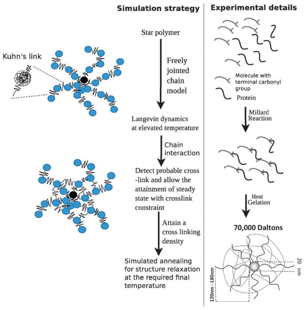
We model the polymer microstructure as a fixed number of strands attached to a core, which mimics the experimentally inferred architecture for this material, see Fig. 1, where each strand is modeled as connected segments of freely jointed chains (FJCs). The core radius is set to a = 10 nm following the experimental estimates of Coll Ferrer et al.11,16 For simplicity, we set the size of each bead in the arms to be the same as that of the core, i.e., a = 10 nm. The initial microstructure is a unit star polymer with 25 arms attached to a core, with each arm modeled by beads connected through four links in series; that is, each link connecting two adjacent beads in an arm is modeled as a Kuhn spring. Following the reports of Liu et al.,29 and Pelton et al.,30 the stiffness of each link and the equilibrium distance are determined using a freely jointed chain model.
Fig. 1.
Construction of the coarse-grained model for the core–shell polymer based NCs and comparison with the experimental protocol.
The molecular weight of a dextran monomer (denoted by M) is 162 Da.30 For a typical molecular weight of 70 kDa of the dextran polymer used to synthesize the NC (see Fig. 1), the number of monomers per arm is and the number of monomers per per bead is . If the number of Kuhn’s segments per bead is Nk and the size of each Kuhn’s segment is bk, we impose Nkbk = Nb, where b is the size of each monomer. For dextran, bk is 0.44 nm29 and the size of the monomer (b) is 1.5 nm using which we calculate the stiffness (ks) of the links between beads as derived from the FJC model, i.e., . We also model the stiffness of the coarse-grained crosslinks to be identical to the stiffness of each link.
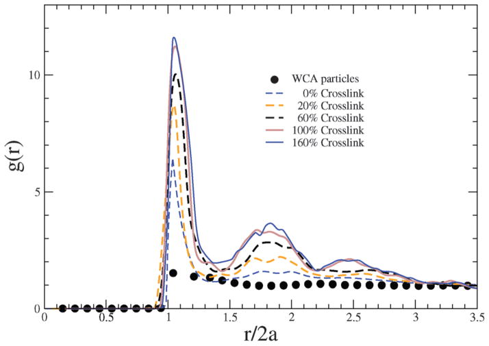
We mimic the experimental protocol to obtain a relaxed structure of the polymer assembly (see Fig. 1): (1) we use molecular dynamics simulations to relax the structure at 1200 K. (2) At this high T, we track individual beads and the inter-bead distances between the pair of beads from two different chains. If the center-to-center distance between beads is less than 19.7 nm – this is the distance from a given bead at which the probability to find a neighboring bead approaches zero, as evident from the radial distribution functions discussed below –, we assign a crosslink between the beads. (3) We repeat the crosslinking process for different pairs of beads until we reach the desired crosslinking density. (4) Once crosslinked, the interaction between the beads is augmented by a harmonic potential. (5) We then follow a simulated annealing protocol described by Beers31 in order to relax the crosslinked structure of the assembly to 300 K. For each crosslinking density we model 4–5 configurations (replicas) and then carry out Brownian dynamics simulations as described by eqn (11) in each of the replicas. The error bars of the reported quantities are determined through the standard deviations of the five replicas.
3 Simulation methodology
We solve the equations of motion of a system of connected beads in a solvent with the following parameters: the mass of each bead is m, the radius is a, the velocity is v, the fluid viscosity is μ and fluid velocity is v∞. The equations of motion for one bead are given by:
| (1) |
where Fbr denotes Brownian forces and Fnbr denotes non-Brownian forces due to inter-bead interactions such as due to harmonic potentials constraining the beads and excluded volume interactions between beads. We consider time scales larger than the inertial relaxation time i.e., , where ξ = 6πμa, for which, following Ermak and McCammon32 we reduce eqn (1) to:
| (2) |
Here, for a given bead, is the mobility, and r is the position. We consider unconstrained Brownian forces as white noise which yields the following expressions:
Here, I is the unit second-order tensor, kB is the Boltzmann constant, T is the temperature, and δ(t − t′) is the Dirac delta function.
In addition to Brownian forces, the beads experience the following non-Brownian forces: (1) Fs represents the spring restoring forces derived from a harmonic potential between adjacent connected beads:
| (3) |
where ro is the equilibrium bond distance, which is set to 2a. Excluded volume interactions between beads is considered through the Weeks–Chandler–Anderson potential:33
| (4) |
for r ≤ rC and = 0 for r > rC; here, is the scaled interaction strength and σ is the excluded volume radius which we set to σ = 2a; the cut-off radius for the WCA potential is rC = 21/6σ and we set ε = 0.7kBT.
So far, the equations of motion have been described just for one bead. Below, we consider multiple beads and hydrodynamic interactions (HI) between two beads mediated by the solvent by adopting the Rotne–Prager–Yamakawa hydrodynamic mobility tensor34,35 to introduce the effect of bead-to-bead hydrodynamics. For a pair of beads i and j, the pair-wise mobility is a function of configuration and is given by:
| (5) |
where the superscript HI indicates hydrodynamic interactions, rij = r is the relative position vector between beads i and j while rr/r2 is the product of normalized vectors. Since the mobility, formally valid at large separations, i.e., for r ≥ σ, as shown in eqn (5), decays slowly, (i.e., as ), the pairwise additive contribution of the hydrodynamic interaction term is still significant for interactions with the image beads of the periodic system, which is conceived as a 3D lattice system of identical cells of volume V; each image cell is denoted by an index l (see below) and contains the same number of beads N. We follow the Ewald summation method described by Beenakker28 to account for the interactions from the periodic images. The resultant velocity is a product of the mobility resulting from the Ewald sum, and the forces acting on the bead, i.e.:
| (6) |
where is the distance between bead i in the central simulation box and bead j in the image replica indexed by l, which is comprised of the components of the 3D lattice vector expressed as l = (l1L, l2L, l3L) and L is the length of the simulation box. The central simulation box is given by l = 0 and the distance between bead i and bead j in the central box is therefore which for simplicity is just denoted by rij; with this simplification in the notation, . The mobility term for r < σ, does not contribute to the long-ranged hydrodynamic interaction, and hence it is added separately only for l = 0. These considerations collectively lead to the relationship:
| (7) |
Eqn (7) defines the pair-wise mobility Mij, which includes hydrodynamic interactions and contribution from image-replicas:
| (8) |
Here, M(1) and M(2) are functions of the inter-bead distance, derived by Beenakker.28 The lattice sum over M(2) is in reciprocal space over reciprocal lattice vectors k, where k = 2πM/L, and m = (m1, m2, m3), which all take integer values. We check for the convergence of the mobility tensor in determining the number of lattice vectors and k-points, and to justify the value of ζ; specifically, we use 125–216 k-points, 27–125 lattice vectors, and set . The sum mentioned in eqn (7) is only valid for r > 2a, and hence, to introduce the effect of overlapping beads, the term shown in eqn (5) for r <2a is added to keep the Rotne–Prager–Yamakawa tensor (Mij) positive-definite for all configurations.36 Since, the term associated with r <2a does not contribute to the long-ranged part of the Rotne–Prager–Yamakawa tensor (i.e., it only survives for n = 0), it is kept out of the real space lattice sum, and is added outside the sum.
The resulting equations of motion are given by:
| (9) |
Here, Δt is the time-step of integration, B is a weight factor, and n is a random vector chosen from a Gaussian distribution of zero mean and unit variance. B is computed by the decomposition of M, i.e.,
| (10) |
We follow the Cholesky decomposition to compute B from the Rotne–Prager–Yamakawa tensor.
We scale time t with the relaxation time of diffusion (where Do is the unconstrained diffusivity of a Brownian bead given by ), we scale r with a, M is scaled by , and F with . We use a nondimensional form of the spring energy, in terms of , which is a non-dimensionalized stiffness constant. In general, we use an over-bar to signify the non-dimensionalized form of the parent variable. We rewrite eqn (9) in-terms of scaled variables to yield:
| (11) |
Here, Pe is the Péclet number and the overbar is used to represent the scaled variables. We use the forward explicit Euler time integration method to discretize eqn (11) and solve for the time evolution of the positions of the beads. We set the viscosity of the blood plasma (μ) to be 1.3 mPa s, and the temperature T to be 300 K.
For the WCA potential, the inertial time τWCA is (where, m is the mass of a bead), while for Brownian dynamics, the time scale (τBr) is . We find that for our system: . We note that one can estimate the collisional time for WCA particles in the condensed phase based on an effective thermodynamic potential given by −kBT ln g(r), where g(r) is the radial distribution function introduced below; we find that the estimate for the collisional time is larger than τWCA.
The value of the time step of integration (Δt) we use, ranges from , which is (much) smaller than both τWCA and τBr, hence easily satisfies the linear stability criterion. The initial configuration (generated by the simulated annealing protocol) is allowed to equilibriate for 1 × 10⁴ to 1 × 10⁶ time steps; we note below that this length of time exceeds the slowest timescales of relaxation typical for our systems, thereby ensuring equilibrium.
The configurations are then subjected to Brownian dynamics simulations. Following Grest et al.37 for 0% crosslink NCs, the largest relaxation time is . NCs with large degree of crosslinking will relax like a hard sphere of equivalent radius of gyration, and the corresponding relaxation rate is smaller than that for star polymers. We first simulate the production runs for . We save the last configuration, which is then used as the initial configuration for the next simulation run, which is executed for a period of . For each configuration (replica), we perform atleast 3 independent simulations with different initial conditions. We repeat these steps for 4–5 independent configurations (replicas with varying internal structures). The procedure for estimating the statistical error is based on computing the standard deviation across these replicas, as noted earlier.
Overall, the position vectors of beads are recorded for 2.5 × 10⁶–5 × 10⁷ time steps. The computations for a typical trajectory noted above require 4 CPU-weeks on a single core of an Intel Xeon 2.7 GHz workstation.
4 Static properties: results and discussion
4.1 Radial distribution function
The radial distribution function quantifies the spatial variance of density of beads and it is defined as:
| (12) |
where ρ is the number density . With increasing degree of crosslinking, each bead is connected to more number of beads through harmonic interactions, which leads to crowding of the beads in the nearest neighbor coordination shell around a given bead. In Fig. 2, g(r) is plotted against the scaled bead-to-bead distance, with the relative height of the first peak indicating how crowding is impacted by the degree of crosslinking.
Fig. 2.
Radial distribution functions of bead positions in NCs with different crosslinking densities. For comparison, the g(r) for an equivalent system of free WCA particles (i.e., not constrained by any Kuhn or crosslinking interactions) is also depicted.
Since the beads in NCs are in close proximity, crowding of beads also likely impacts the movement of each test bead. Hence, we use a Voronoi diagram analysis in order to allocate a fluid volume element to each bead, and we calculate the neighbor statistics and the volume of the Voronoi elements for each bead. We follow Rycroft38 to generate a Voronoi volume around each bead (Fig. 3(a)). However, since the beads are clustered in a network, leading to an inhomogeneity in the structure, an irregular Voronoi tessellation is more appropriate for such structures, as depicted in Fig. 3(b).
Fig. 3.
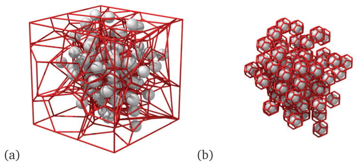
(a) Periodic Voronoi tessellation around the beads, (b) irregular Voronoi tessellation around the beads of the NC; here the gray spheres represent the beads and the red lines represent the skeleton of the Voronoi tessellated lattice.
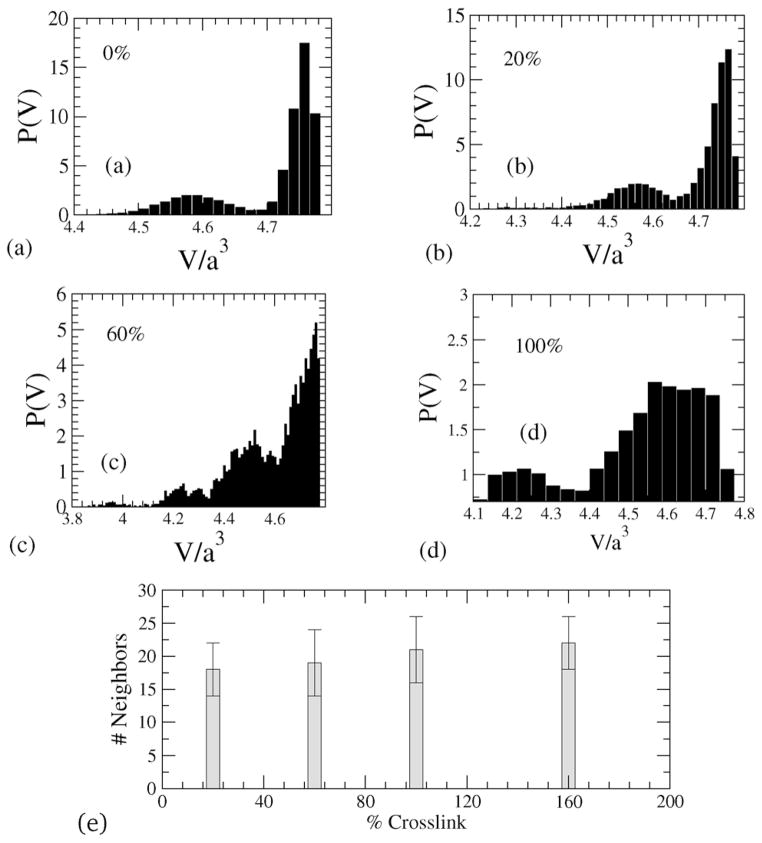
A star polymer without any crosslinking shows arm retractions, which can be captured by collecting the volume of each Voronoi cell and then plotting the probability density function of the Voronoi-cell volumes of the beads. In Fig. 4 the probability distributions of Voronoi-cell volumes for different crosslinked densities are shown. The characteristic bimodal distribution is a reflection of the star-shaped conformation of the NC, where there is a clear separation of the Voronoi-cell volumes associated with the outer radial (arm) regions, and those in the inner-regions of the NC including the core, see Fig. 5. With increasing crosslinking, the distribution of volumes shifts and the demarkation of the two afore-mentioned regions becomes increasingly nebulous.
Fig. 4.
(a–d) Distributions of Voronoi tessellated cell volumes (P(v)) for different crosslinking densities, and (e) number of nearest neighbors for different crosslinking.
Fig. 5.

Schematic of a star polymer configuration. The two headed arrow shows the direction of arm retractions.
With increasing crosslinking the distribution of nearest neighbors is also altered. Specifically, to estimate the number of nearest neighbors, we calculate the area around a bead and divide by the projected area between a pair of beads, (which for spherical beads would yield a value of π in scaled units). The average number of nearest neighbors (over a period of is estimated to be between 16–20) and is plotted against % crosslinking in Fig. 4(e), which clearly shows that with increase in crosslinking, there is a corresponding increase in the crowding of beads.
4.2 Radius of gyration and diffusivity
In order to characterize the size of the NC, we compute the radius of gyration (Rg) based on bead positions. For a model with all the beads having the same mass, the radius of gyration tensor (G) is defined as
| (13) |
where cm denotes center of mass of the NC beads. The characteristic size along three orthogonal directions is denoted by the eigenvalues λi (i = 1, 3) of the matrix G, and the radius of gyration is defined as:
| (14) |
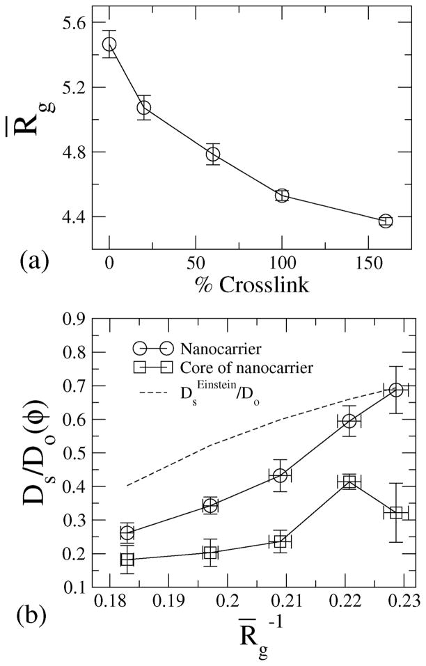
In Fig. 6(a), the radius of gyration is plotted against the cross-linking density, showing that with increasing crosslinking, the radius of gyration decreases.
Fig. 6.
(a) Radius of gyration of NCs for various crosslinking densities; the radius of gyration is nondimensionalized with the radius of the beads. (b) Diffusivity of the beads and of the core of the NC against the radius of gyration, Rg.
Since, the NC size is shown to decrease with increasing crosslinking, we hypothesize that the crosslinking will also influence the self diffusivity of NCs. To test this hypothesis, we compute the mean squared displacement (MSD) and the self-diffusivity (Ds) of the NC. MSD is defined as:
| (15) |
where ri represents the absolute position of bead i, Ds is self-diffusivity of the NC and t is the trajectory time. Here, the ensemble average is taken over all the beads.
For 160% crosslinked NCs, the radius of gyration Rg/a ≈ 4.3 ± 0.3 and the self-diffusivity is calculated to be Ds/Do ≈ 0.15. It is already evident from the g(r) data (Fig. 2) that the 160% crosslinked microstructures represent the highest degree of closed packing in terms of conformations. We, therefore, compare the diffusivity of the 160% crosslinked nanocarrier with theoretical prediction for hard spheres; we compute the volume fraction based on radius of gyration of the 160% cross-linked nanocarrier and compute the corresponding diffusivity based on Einstein’s correction to intrinsic viscosity of hard spheres, i.e., . The calculated diffusivity of the NC based on MSD is i.e. . This computed value is in close agreement with the estimate based on the Einstein correction; for a hard sphere of radius 4.3a, φ = 0.15 and , suggesting that the 160% crosslinked NC shows diffusion very similar to that of hard spheres. We plot against Rg for the NC and for the NC-core in Fig. 6(b). The diffusivity varies inversely with the radius of gyration for the NC as well as for the NC-core. It is clear from Fig. 6(b) that the core of the NC microstructure also exhibits Brownian motion. Since the environment surrounding the core has the highest density of beads, the diffusivity of the NC-core is reduced relative to that of the NC. However, since the core follows the center of mass of the NC, the self-diffusivity of the core tracks that of the center of mass of the NC microstructure, and with increasing diffusivity of the NC, the self-diffusivity of the core also increases (see Fig. 6(b)).
The characteristic size of the NC can be estimated from the root-mean-squared end-center distance, which is a closely related quantity to the radius of gyration. If there are f number of arms, with Nb, number of beads in each arm, then the mean-squared end-center distance is defined as:
| (16) |
where rcore is the position of the core and rk,Nb is the position of the last bead in the kth arm. We compute the end-to-center distance (Rarm) of the NC using eqn (16). Significantly, the simulated end-to-center distance of the polymer is estimated to be 144–184 nm (for the crosslinking density in the range 20–160%), which compares very favorably to the measured size of 120–180 nm for the NC.16 This favorable comparison justifies our choice of utilizing 25-arms per NC in our coarse-grained model.
4.3 Structure factor
To complete our analysis of the NC structure, we compute the structure factor, defined as:
| (17) |
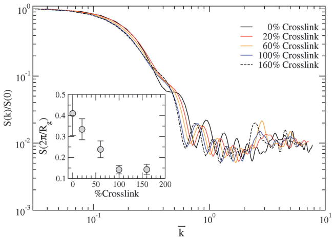
where k is the wave vector, rj represents the position of bead j, and the average represents an average over the trajectory. In Fig. 7, we choose k = (k, 0, 0) and plot S(k) against k. The large k behavior characterizes the NC internal structure (form factor), while the small k behavior characterizes the overall NC packing. In particular, we argue that will track the overall compressibility of the NC. This value of k can also be regarded as differentiation between the large k behavior and the small k one. We note that the justification for scaling k with Rg (instead of with a) is based on the models proposed by Grest et al.18 and by Prentis,19 where eqn (17) is approximated in the limit kRg ≪ 1 as:
| (18) |
Fig. 7.
Static structure factor S(k) and (inset) at various crosslinking densities. The wave vectors are scaled with i.e. .
Hence, when we rescale k with and plot in Fig. 7, we find that the data collapse onto a single master curve for kRg ≪ 1 (specifically for ). The terrace-like behavior for k̄ ≪ 1 also consistent with the trends reported in other computational studies of star polymers of large molecular weights, and in neutron scattering of microgels.39 The differences in the curves for k̄ > 1 reflects the differences in the internal structure of the NC (or in form factors) caused by changing the crosslinking densities.
Since, with increasing crosslinking, the radius of gyration decreases (see Fig. 6(a)), we surmise that the normal stress or pressure (P) should scale as , (i.e. increases with increasing crosslinking). We show in Fig. 7 (inset) that decreases with increasing crosslinking, which indicates an increase in compressibility as a consequence of increased pressure. In this discussion, the scaling exponent d can simply represent the dimensionality for dilute systems, or can be significantly different from dimensionality for strongly correlated systems; we explore this scaling of pressure with Rg in a later section dealing with the direct calculation of stresses.
The static properties discussed here will also be impacted by the deformation of the NC under shear flow, which is discussed in Section 5.
5 Dynamic properties: results and discussion
The dynamic properties are studied to investigate the response of the NC to shear forces. The context we consider is that of blood capillaries of radius typically 5 times the radius of red blood cells (RBCs). The characteristic radius of a RBC is aRBC = 2.5 μm. Under flow, the RBCs in a capillary migrate to the center, therefore, causing the NCs to marginate to the cell free layer.3 The cell-free layer represents the gap between the RBC-occupied core and the wall of the capillary, which is 2aRBC (see Fig. 8). We consider a physiologically relevant shear near the endothelium (shown in Fig. 8). Yeh and Eckstein40 have measured wall shear in blood flow in the range of 785–1250 s−1. Considering the viscosity of blood plasma as 1.3 mPa s, and based on our bead radius a, we calculate the maximum Péclet number to be 5. However, we explore the range of 0 ≤ Pe ≤ 5, where the lower end, the range corresponds to the flow rate in smaller capillaries as well as lymphatic flows.3,41
Fig. 8.
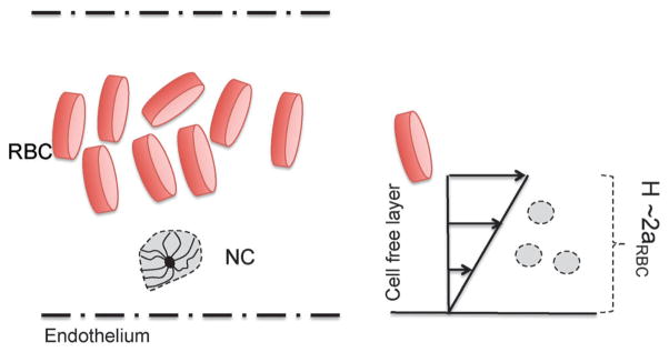
Schematic of a marginated NC in a blood capillary near the endothelium.
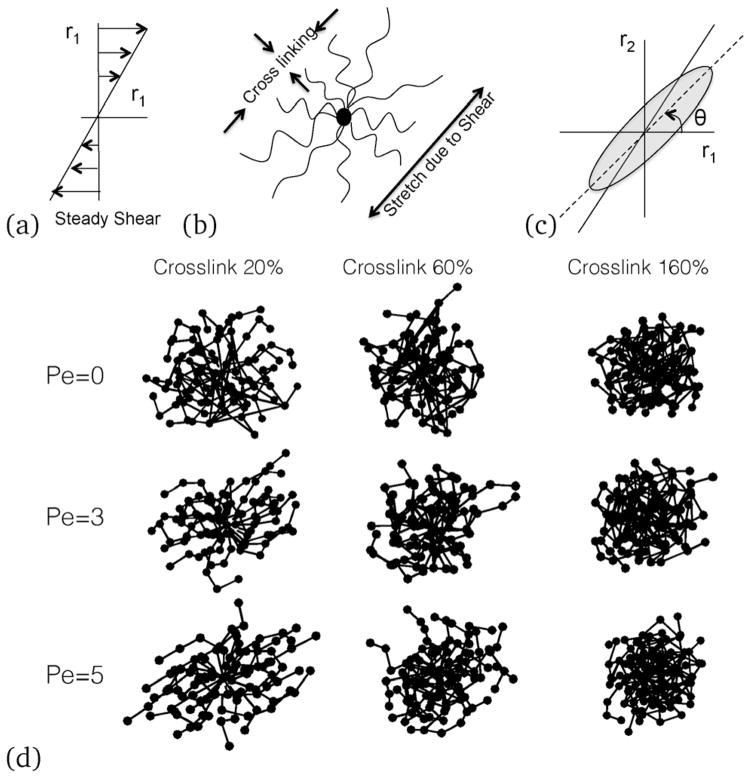
In our simulations, a steady shear is applied along the r1–r2 direction, where r1 is the shear direction and r2 is the gradient direction, see Fig. 9(b). We solve eqn (11) for bead positions with the Lees–Edward boundary condition42 for a given shear rate. We mostly represent our results interms of the Weissenberg number (Wi), defined as Wi = γ̇τa, where γ̇ is the shear rate, and τa is the relaxation time of the NC, i.e., . Since Pe is defined in terms of the radius of the beads, for linear polymers . Grest et al.43 investigated the relaxation of self-entangled star polymers and showed that the star polymers relax faster than their linear counter-parts, and that the ratio of the relaxation times scales as . Hence, for the present case, .
Fig. 9.
(a) Direction of the applied shear; (b) schematic of a sheared NC, (c) the angle of inclination of the sheared NC; and (d) simulation results of representative bead positions showing connected bonds. With increasing shear rates, an ellipsoid or a rod-like conformation is observed, which inclines more towards the shear direction at an angle θ to shear direction. With increasing crosslinking, the nanocarrier changes the inclination angle as well as the shape.
Under shear (see Fig. 9(a)), the NC undergoes stretching and the crosslinked bonds resist deformation (see Fig. 9(b)). Depending on the crosslinking density and the shear rate, the NC orients at an angle θ with the shear direction (see Fig. 9(c)). While the angle θ contains critical information about the strain response of the NC, crosslinking of the deformation of the NC along r3 (orthogonal to the shear plane) would also depend on the shear rate (see Fig. 9(d)). Internal stresses originate from bead-to-bead interactions and stretching of the bonds. In particular, the configurational stresses arise from bond stretching, while forces due to deformation can lead to an increase in the collisional stresses.
In addition to the internal stresses, the tumbling of the NC can cause an additional mode of relaxation to an already complex phenomenon. Hence, below, we explore the effect of the shear and crosslinking on the NC shape, deformability, tumbling behavior, shear and normal stress distributions.
5.1 Shape of the NC under shear
Deformation of the NC is computed from the components of the radius of gyration tensor (G). Eigen values of the radius of gyration tensor defined in eqn (13) are used to calculate the degree of prolateness, defined as,
| (19) |
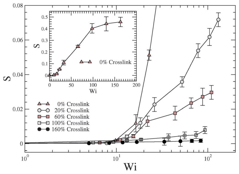
where . In prior studies S has been shown to vary from −0.25 to 2, where the change in the sign from ‘−ve’ to ‘+ve’ signifies an oblate to a prolate shape change.43 In Fig. 10, S is plotted against the shear rate, and as is evident, with increasing shear rate the NC undergoes deformation and assumes a shape that is similar to a prolate spheroid. In particular, the NC without crosslinking undergoes a large deformation (see the inset of Fig. 10), and with increasing crosslinking densities, the degree of prolateness is smaller, Fig. 10.
Fig. 10.
Prolateness of NCs versus shear (Pe) and crosslinking density.
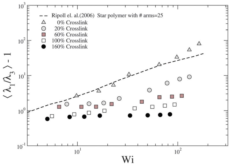
Ripoll et al.20 have investigated the effect of shear on the asphericity of a star polymer, which is a measure analogous to S. To quantify the extent of deformation due to shear, the asphericity is computed as , where λ1 ≥ λ2 ≥ λ3, see Fig. 11; we note that corresponds to a sphere. We find that for the NC with 0% crosslink which is closest to the star polymer approximation, our results are in close agreement with those of Ripoll et al.20 as shown in Fig. 11.
Fig. 11.
Degree of deformation of NCs for various shear rates and cross-linking densities, quantified in term of the asphericity.
With increasing crosslinking the resistance to deformation increases and hence our results deviate from the 0% crosslink density case. In particular, the deformation is low and shows a much weaker dependence on Pe. However, as discussed later, the deformation along the gradient direction offers information on the effect of shear on the stiffness of the NC.
5.2 Internal structure of the NC under shear
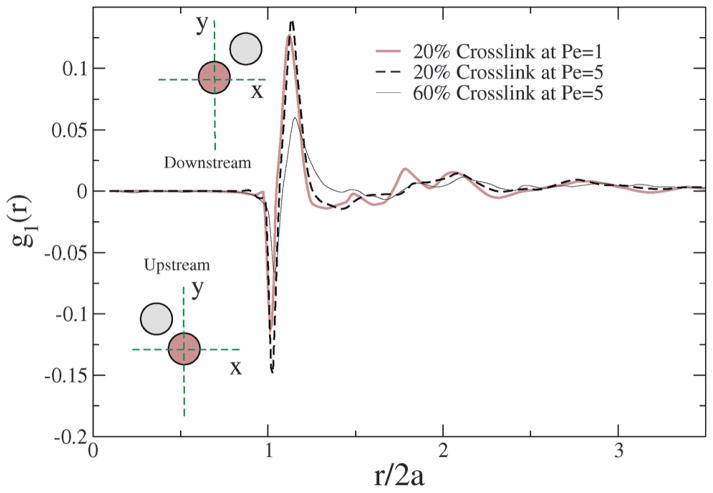
We now consider how the spatial distribution of beads is perturbed in the shear flow field. Unlike the zero shear case considered in Section 4, we consider the radial distribution function as a perturbation expansion along the plane of shear, and compute the 1st perturbation of the radial distribution function shown in eqn (20). Strating44 has showed that
| (20) |
Here, go(r) is the equilibrium radial distribution function, g1(r) is the 1st perturbation to the radial distribution function g(r). The orientation in the stretch direction is represented by θ, and φ represents the azimuthal angle. In Fig. 12, we plot g1(r), which we calculate using the relationship:
| (21) |
Fig. 12.
1st perturbation to the radial distribution function in the shear flow field for different crosslinkings and Péclet numbers.
In a shear field, two beads approach each other in the upstream configuration and rotate to a downstream configuration. In the upstream configuration, g1(r) is negative while in the downstream configuration it is positive; however, the spring restoring force acts against shear, and since the beads are connected, a given pair of beads that rotates from upstream to downstream also show spring and tumbling relaxations that depend on Pe and the degree of crosslinking of the NC. Hence, the internal structure of the NC gets perturbed by the shear, and the degree of perturbation is strongly dependent on Pe and % crosslinking.
Due to the prolate shape of the NC (see Fig. 10), the majority of the bead-to-bead contacts originates from the orientation orthogonal to the shear direction, chiefly contributed by the deformation. Since, the difference in the area under the g1(r) curve is anti-symmetrical (i.e. the depletion upstream is matched by the enhancement downstream), the collisional stresses contribute less to the overall shear stress. Hence, for a given crosslinking density, there is no significant change in the g1(r) function with Pe. For a similar shear rate, however, with increasing crosslinking, there is a significant shift in the g1(r) curve, suggesting that the increased crosslinks cause the NC to resist shear deformation, and perhaps contribute significantly to the build-up of internal stress. In Section 5.4, stresses computed independently from the Virial expression also support the observations gleaned from the 1st perturbation to the radial distribution function.
5.3 Comparison of NC deformation under shear with related models of polymer assemblies
The stresses induced are caused by the stretching of bonds which results in deformation of the microstructure and the corresponding strain is computed from the components of the radius of gyration tensor (G). The configuration thickness (δ2) is defined as
| (22) |
The ratio of shear and the normal strain difference determines the orientation45 of the NC, given by:
| (23) |
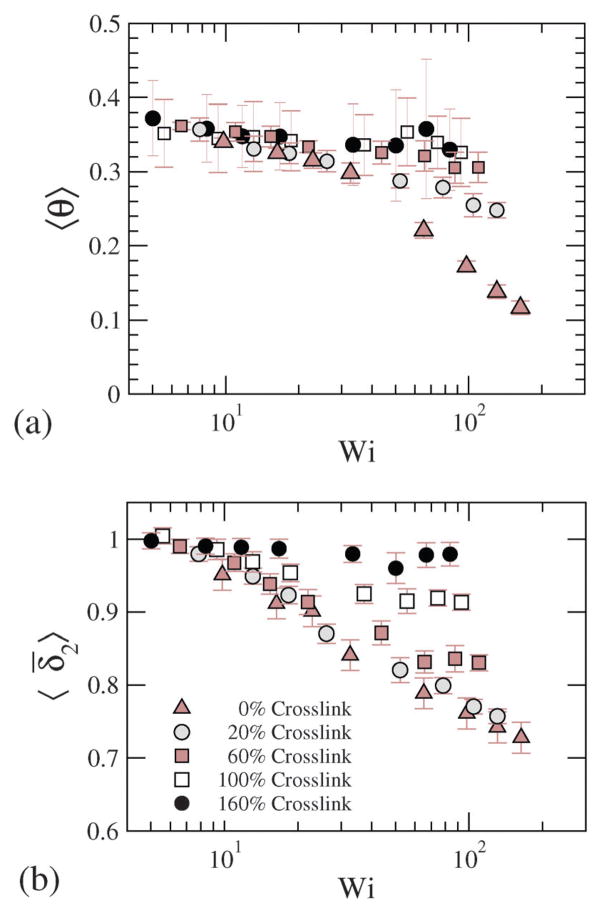
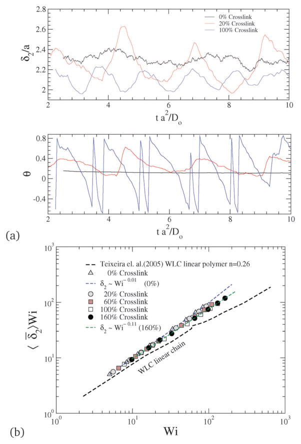
where θ is the configurational orientation of the NC. The configurational thickness and configurational orientation calculated from eqn (22) and (23) are plotted in Fig. 13, where 〈θ〉 and 〈δ̄2〉 for various shear rates and crosslinking densities are depicted. Since the applied shear is in the r1 direction, with r2 being the gradient direction, G12 represents the shear strain, and G11–G22 represents the 1st normal strain difference. We plot the configuration thickness as well as the NC orientation against time in Fig. 14(a), which together indicate how the configuration thickness associated with the change in shape of the NC is related to the NC tumbling motion. The correlated motion in θ versus t and δ versus t clearly suggests that the tumbling motion is a mechanism by which the system relieves the build-up of internal stress. It is also intriguing to note that the tumbling relaxation time is highly sensitive and decreases with the increasing degree of crosslinking.
Fig. 13.
(a) Configurational orientation and (b) configurational thickness for various Wi and crosslinking densities.
Fig. 14.
(a) Time evolution of configurational thickness and NC orientation for various crosslinking densities at Pe = 5. (b) Configurational thickness resistance for various Wi and crosslinking densities.
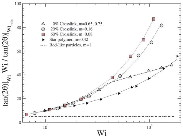
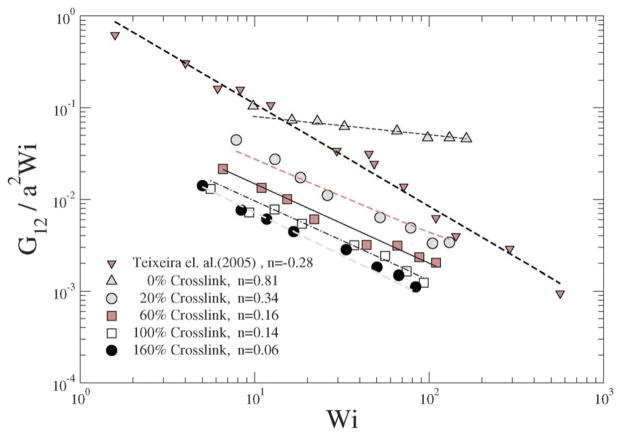
In a linear response model, the ratio of the applied force to the deformation represents a “stiffness”: for e.g., in the case of a Hookean spring, the stiffness constant Kspring = |force|/|displacement|. Since, δ2 depends on Wi, Teixeira et al.45 have introduced a general relationship: 〈δ2〉 ~ Wi−n in order to compare various models. Since Wi can be regarded as an applied force and 1/δ2 as an effective deformation, the stiffness or resistance to configurational thickness can be measured by the product 〈δ2〉Wi. Fig. 14(b) shows the averaged configurational thickness resistance (〈δ2〉Wi). Fits to the data indicate the configurational thickness resistance increase with increasing crosslinking. That is, the configuration thickness scales as Wi−0.01 for 0% crosslinking and as Wi−0.11 for 160% crosslinking. Teixeira et al.45 have previously shown that for a linear worm-like chain (WLC) polymer system 〈δ2〉 ~ Wi−0.26. Here, compared to the Teixeira et al.45 result for a soft linear system, 〈δ2〉 is a relatively weak function of Wi for all NCs. Due to the prolate shape of the NC under shear, the stresses are not only dependent on the deformation but also on the orientation of the nanocarrier, which is evident from Fig. 13 and 14. In particular Fig. 10 and 11 show that under shear, a large degree of crosslinking leads to sphere-like shapes, while a smaller degree of crosslinking leads to NC shapes approaching rod-like geometries. Moreover with the deformation field along the r1–r2 direction, and increasing shear, the NC tumbles (Fig. 14(a)) and the average orientation over the tumbling cycle gives important information regarding the ratio of shear strain to normal strain difference, see eqn (23). The rheological response of rod-like particles, under small shear, is described by G12 ~ Pe and (G11–G22) ~ Pe2,46,47 for which . Since Wi ~ Pe, the scaling for rod-like particles corresponds to tan(2θ) ~ Wi−1, as indicated in Fig. 15.
Fig. 15.
for various Wi and crosslinking densities.
In contrast, a star polymer’s orientation can be expressed as a function of Wi and it has been shown that tan(2θ) ~ Wi−m, where m ~ 0.35–1.20,21,45 In Fig. 15 we plot for various shear rates and crosslinking densities, and show the corresponding fits to the data by reporting the values of m; we omit results for large crosslinking densities (100% and 160%) due to their spherical shape (see Fig. 13). It is evident that the behavior of the NC with smaller degrees of crosslinking approach the scaling for rod-like particles.
For ultra soft colloids investigated by Singh et al.21 m = 0.43, by Ripoll et al.20 m = 0.35, while Teixeira et al.45 have shown that for long linear WLC polymers, m = 0.46. Our results in Fig. 15 indicate that m decreases with decreasing crosslinking; stated differently, m decreases as the degree of deformation (shown as in Fig. 11) of the NC increases.
In Fig. 16, the ratio of shear strain G12 to Wi is plotted for various shear rates and crosslinking densities. A decrease in indicates a decrease in the first normal strain coefficient which is akin to the effective viscosity of a single NC,45 which is observed for increasing crosslinking. In particular, the exponent governing the decrease in the first normal strain coefficient with Wi of the crosslinked NC is similar to that reported in single molecule experimental results shown by Teixeira et al.45 The 0% crosslinked NC at a large shear rate, is highly stretched and approaches G12 ~ Wi, which is close to that for a rod-like polymer response to steady shear flow.
Fig. 16.
for various Wi and crosslinking densities. The data are fit to a power law curve: G12 ~ Win.
5.4 Internal stresses and stiffness of the NC under shear
We calculate internal stresses to estimate the response of the NC to the observed structural changes. Following Irving and Kirkwood,48 (see Appendix A for derivation) stresses are calculated using the expression:
| (24) |
where σ is the stress tensor, Fij is the force on bead i due to bead j, and rij is the distance vector between the beads i and j.
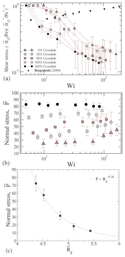
In Fig. 17(a) the shear stresses are plotted for various shear rates, confirming that the NC under shear shows shear thinning akin to Fig. 16, and the shear thinning effect is significantly higher than that reported for hard sphere suspensions.49
Fig. 17.
(a) Shear stress ; (b) normal stress at different crosslink densities; and (c) normal stress plotted versus the radius of gyration.
We have shown that with increasing crosslinking the radius of gyration of the NC decreases (Fig. 6) and the stiffness of the NC increases (Fig. 7), causing us to hypothesize that there is a likely build-up of normal stress. To directly test this hypothesis, we compute the trace of the stress tensor, i.e., Fig. 17(b), the computed normal stress is plotted for various shear rates and for different crosslinking. For smaller crosslinking the normal stress increases with shear, and the shear dependence gets weaker with increasing crosslinking density; for the largest crosslinking we consider the normal stress is independent of shear. This trend is also consistent with those discussed in Fig. 11, which shows that the deformation of a highly crosslinked NC is a weak function of shear. Our data in Fig. 17(c) validate our hypothesis that the stiffness of the NC originates from the osmotic pressure by clearly showing that with decreasing radius of gyration, the normal stress increases. For dilute suspensions, the osmotic pressure ~ Rg−3, however as shown in the figure, the exponent of −8.28 indicates that the intrinsic stress build-up is significantly larger than that expected from a dilute system. Below, we explore the mechanism contributing to the intrinsic stress through a simple theoretical model from the literature.
In their textbook, Dill and Bromberg50 have described a network of freely jointed chains to explain the elasticity of networked polymers and have expressed the free energy (F) as a function of strain subject to a volume conservation constraint, given by:
| (25) |
where, the elongation ratio (where Lo = LWi=0) and is a modulus of elasticity. We approximate the volume of the NC at Wi = 0 as a sphere of diameter Lo (i.e. Lio = Lo). For Wi > 0, the normal stress difference (based on the direction of stretching) deforms the NC from a sphere to an ellipsoid. From the volume conservation condition we get:
| (26) |
The normal stress difference defined as:
| (27) |
where σ1′ is the stress along the direction of stretch and σ2′ and σ3′ are stresses orthognal to σ1′. We assume that the deformation of the NC is symmetric along the directions orthogonal to stretching direction i.e. L1 = L and L2 = L3. We obtain from eqn (25) and (26):
| (28) |
In the above-described model, it can also be stipulated that the network consists of m freely jointed chains each with Nk links of length bk, and one can relate the force (f1) needed for a given elongation L1, from which the force per unit area can be written as:
| (29) |
Comparing eqn (28) and (29), . For small elongations we assume that L̄ = 1 + ε and we get:
| (30) |
If C is the modulus of elasticity of the NC, then . We calculate the eigenvalues of the radius of gyration tensor eqn (13). We define the elongation L as where λ1 is the eigenvalue of the radius of gyration tensor along the direction of elongation. Similarly, we calculate the eigenvalues of the stress tensor eqn (24) and the normal stress difference is calculated from eqn (27). In Fig. 18 the normal stress difference σN′ is plotted against elongation L̄.
Fig. 18.
Normal stress difference versus elongation for various cross-linking densities.
We fit the data for the normal stress difference for each crosslinking density (dotted lines in Fig. 18) for small elongations as shown in eqn (28), from which we further estimate the elasticity modulus (C). We find that with increasing crosslinking the elasticity modulus increases from 0.4 to 15 kPa.
We also compare the calculated stiffness of the NC with previously measured stiffness of soft and hard biomaterials in Table 1, and we find that the stiffness of the NC falls in the range of moderately soft materials.
Table 1.
Computed stiffness of the NC and the measured structural stiffness of common biomaterials
| Material type | Method | Stiffness | Ref. |
|---|---|---|---|
| Confluent endothelial monolayers | Experimental | 0.1–0.8 Pa | Dewey et al.51 |
| Chondrocytes | Experimental | 0.5 kPa | Hochmuth52 |
| Human platelets | Experimental | 1.5–4 kPa | Mathur et al.53 |
| Endothelial cells | Experimental | 1.4–6.8 kPa | Mathur et al.53 |
| Nanocarrier | Calculated (this work) | 0.4–15 kPa | |
| Skeletal muscle cells | Experimental | 24.7 ± 3.5 kPa | Mathur et al.53 |
| Cardiac cells | Experimental | 100.3 ± 10.7 kPa | Mathur et al.53 |
6 Conclusions
We have developed a model for a new class of highly deformable polymer based NCs synthesized by Coll Ferrer et al.11,16 and Ferrer et al.15 We have explored zero shear properties of the microstructures and have demonstrated the effects of physiologically relevant shear on the structure and dynamic properties of the NC. Our findings are also consistent with other theoretical findings in limit cases. We believe that the development of such models is essential to gain useful insights that can be translated into the optimal design of nanocarriers for targeted drug delivery. Future work will focus on combining this model with previous models for functionalized NCs54,55 to include adhesive interactions, along with experimental investigation in vitro and in vivo. Together, these will advance our understanding of the binding affinities of soft crosslinked NCs to cells.
Acknowledgments
We acknowledge support from NIH through grant NIH 1R01EB006818-05. Computational resources were provided in part by the National Science Foundation grant DMR-1120901, and by the Extreme Science and Engineering Discovery Environment (XSEDE) grant MCB060006.
A Intrinsic stress
Following Irving and Kirkwood,48 the stress tensor is given by:
| (31) |
where, Oij is the differential operator given by:
| (32) |
We scale stresses by nkBT, where n is the number density of beads, kB is the Boltzmann constant, and T is the temperature, and rewrite the expression for stresses as:
| (33) |
Here, τI is the inertial relaxation time and τD is the relaxation time due to diffusion. Following eqn (3), we impose a force balance in the limit of . The stresses are computed using eqn (33), with the differential operator truncated to the 1st order approximation, i.e. with Oij = 1. This leads to eqn (24).
References
- 1.Muzykantov VR, Radhakrishnan R, Eckmann DM. Curr Drug Metab. 2012;13:70–81. doi: 10.2174/138920012798356916. [DOI] [PMC free article] [PubMed] [Google Scholar]
- 2.Ayyaswamy PS, Muzykantov V, Eckmann DM, Radhakrishnan R. J Nanotechnol Eng Med. 2013;4:011001. doi: 10.1115/1.4024004. [DOI] [PMC free article] [PubMed] [Google Scholar]
- 3.Swaminathan TN, Liu J, Balakrishnan U, Ayyaswamy PS, Radhakrishnan R, Eckmann DM. IUBMB Life. 2011;63:640–647. doi: 10.1002/iub.475. [DOI] [PMC free article] [PubMed] [Google Scholar]
- 4.Champion JA, Mitragotri S. Pharm Res. 2009;26:244–249. doi: 10.1007/s11095-008-9626-z. [DOI] [PMC free article] [PubMed] [Google Scholar]
- 5.Geng Y, Dalhaimer P, Cai S, Tsai R, Tewari M, Minko T, Discher DE. Nat Nanotechnol. 2007;2:249–255. doi: 10.1038/nnano.2007.70. [DOI] [PMC free article] [PubMed] [Google Scholar]
- 6.Kolhar P, Anselmo AC, Gupta V, Pant K, Prabhakarpandian B, Ruoslahti E, Mitragotri S. Proc Natl Acad Sci U S A. 2013;110:10753–10758. doi: 10.1073/pnas.1308345110. [DOI] [PMC free article] [PubMed] [Google Scholar]
- 7.Miller A. Curr Med Chem. 2003;10:1195–1211. doi: 10.2174/0929867033457485. [DOI] [PubMed] [Google Scholar]
- 8.Malmsten M. Soft Matter. 2006;2:760–769. doi: 10.1039/b608348j. [DOI] [PubMed] [Google Scholar]
- 9.Drummond DC, Zignani M, Leroux JC. Prog Lipid Res. 2000;39:409–460. doi: 10.1016/s0163-7827(00)00011-4. [DOI] [PubMed] [Google Scholar]
- 10.Ahmed F, Pakunlu RI, Brannan A, Bates F, Minko T, Discher DE. J Controlled Release. 2006;116:150–158. doi: 10.1016/j.jconrel.2006.07.012. [DOI] [PubMed] [Google Scholar]
- 11.Coll Ferrer M, Dastgheyb S, Hickok NJ, Eckmann DM, Composto RJ. Acta Biomater. 2014;10:2105–2111. doi: 10.1016/j.actbio.2014.01.009. [DOI] [PMC free article] [PubMed] [Google Scholar]
- 12.Conway A, Vazin T, Spelke DP, Rode NA, Healy KE, Kane RS, Schaffer DV. Nat Nanotechnol. 2013;8:831–838. doi: 10.1038/nnano.2013.205. [DOI] [PMC free article] [PubMed] [Google Scholar]
- 13.Eckmann DM, Composto RJ, Tsourkas A, Muzykantov VR. J Mater Chem B. 2014;2:8085–8097. doi: 10.1039/C4TB01141D. [DOI] [PMC free article] [PubMed] [Google Scholar]
- 14.Li J, Yao P. Langmuir. 2009;25:6385–6391. doi: 10.1021/la804288u. [DOI] [PubMed] [Google Scholar]
- 15.Ferrer MCC, Shuvaev VV, Zern BJ, Composto RJ, Muzykantov VR, Eckmann DM. PLoS One. 2014;9:e102329. doi: 10.1371/journal.pone.0102329. [DOI] [PMC free article] [PubMed] [Google Scholar]
- 16.Coll Ferrer M, Ferrier RC, Jr, Eckmann DM, Composto RJ. J Nanopart Res. 2012;15:1–7. doi: 10.1007/s11051-012-1323-5. [DOI] [PMC free article] [PubMed] [Google Scholar]
- 17.Grest GS, Kremer K. Phys Rev A: At, Mol, Opt Phys. 1986;33:3628–3631. doi: 10.1103/physreva.33.3628. [DOI] [PubMed] [Google Scholar]
- 18.Grest GS, Kremer K, Witten TA. Macromolecules. 1987;20:1376–1383. [Google Scholar]
- 19.Prentis JJ. J Chem Phys. 1982;76:1574–1583. [Google Scholar]
- 20.Ripoll M, Winkler RG, Gompper G. Phys Rev Lett. 2006;96:188302. doi: 10.1103/PhysRevLett.96.188302. [DOI] [PubMed] [Google Scholar]
- 21.Singh SP, Chatterji A, Gompper G, Winkler RG. Macromolecules. 2013;46:8026–8036. [Google Scholar]
- 22.Foss DR, Brady JF. J Fluid Mech. 2000;407:167–200. [Google Scholar]
- 23.Hur JS, Shaqfeh ESG, Larson RG. J Rheol. 2000;44:13–742. [Google Scholar]
- 24.Petera D, Muthukumar M. J Chem Phys. 1999;111:7614–7623. [Google Scholar]
- 25.Schroeder CM, Shaqfeh ESG, Chu S. Macromolecules. 2004;37:9242–9256. [Google Scholar]
- 26.Hsieh CC, Li L, Larson RG. J Non-Newtonian Fluid Mech. 2003;113:147–191. [Google Scholar]
- 27.Jendrejack RM, de Pablo JJ, Graham MD. J Chem Phys. 2002;116:7752–7759. [Google Scholar]
- 28.Beenakker CWJ. J Chem Phys. 1986;85:1581–1582. [Google Scholar]
- 29.Liu Y, Lipowsky R, Dimova R. Langmuir. 2012;28:3831–3839. doi: 10.1021/la204757z. [DOI] [PubMed] [Google Scholar]
- 30.Pelton R, Zhang J, Chen N, Moghaddamzadeh A. Tappi J. 2003;2:15–18. [Google Scholar]
- 31.Beers K. Numerical methods for chemical engineering applications in Matlab. Cambridge University Press; Cambridge, New York: 2007. [Google Scholar]
- 32.Ermak DL, McCammon JA. J Chem Phys. 1978;69:1352–1360. [Google Scholar]
- 33.Weeks JD, Chandler D, Andersen HC. J Chem Phys. 1971;54:5237–5247. [Google Scholar]
- 34.Rotne J, Prager S. J Chem Phys. 1969;50:4831–4837. [Google Scholar]
- 35.Yamakawa H. J Chem Phys. 1970;53:436–443. [Google Scholar]
- 36.Zhou T, Chen SB. J Chem Phys. 2006;124:034904. doi: 10.1063/1.2161205. [DOI] [PubMed] [Google Scholar]
- 37.Grest GS, Kremer K, Milner ST, Witten TA. Macromolecules. 1989;22:1904–1910. [Google Scholar]
- 38.Rycroft CH. Chaos. 2009;19:041111. doi: 10.1063/1.3215722. [DOI] [PubMed] [Google Scholar]
- 39.Witten TA, Pincus PA, Cates ME. EPL. 1986;2:137. [Google Scholar]
- 40.Yeh C, Eckstein E. Biophys J. 1994;66:1706–1716. doi: 10.1016/S0006-3495(94)80962-2. [DOI] [PMC free article] [PubMed] [Google Scholar]
- 41.Pan W, Caswell B, Karniadakis GE. Soft Matter. 2010;6:4366–4376. doi: 10.1039/C0SM00183J. [DOI] [PMC free article] [PubMed] [Google Scholar]
- 42.Lees AW, Edwards SF. J Phys C: Solid State Phys. 1972;5:1921. [Google Scholar]
- 43.Bishop M, Michels JPJ. J Chem Phys. 1986;85:5961–5962. [Google Scholar]
- 44.Strating P. Phys Rev E: Stat Phys, Plasmas, Fluids, Relat Interdiscip Top. 1999;59:2175–2187. [Google Scholar]
- 45.Teixeira RE, Babcock HP, Shaqfeh ESG, Chu S. Macromolecules. 2005;38:581–592. [Google Scholar]
- 46.Doi M, Edwards SF. J Chem Soc, Faraday Trans 2. 1978;74:918–932. [Google Scholar]
- 47.Doi M, Edwards SF, et al. The theory of polymer dynamics. Vol. 222 Clarendon Press; Oxford: 1986. [Google Scholar]
- 48.Irving JH, Kirkwood JG. J Chem Phys. 1950;18:817–829. [Google Scholar]
- 49.Bergenholtz J, Brady JF, Vicic M. J Fluid Mech. 2002;456:239–275. [Google Scholar]
- 50.Dill K, Bromberg S. Molecular driving forces: statistical thermodynamics in biology, chemistry, physics, and nanoscience. Garland Science; 2010. [Google Scholar]
- 51.Dewey C, Bussolari S, Gimbrone M, Davies PF. J Biomech Eng. 1981;103:177–185. doi: 10.1115/1.3138276. [DOI] [PubMed] [Google Scholar]
- 52.Hochmuth RM. J Biomech. 2000;33:15–22. doi: 10.1016/s0021-9290(99)00175-x. [DOI] [PubMed] [Google Scholar]
- 53.Mathur AB, Collinsworth AM, Reichert WM, Kraus WE, Truskey GA. J Biomech. 2001;34:1545–1553. doi: 10.1016/s0021-9290(01)00149-x. [DOI] [PubMed] [Google Scholar]
- 54.Liu J, Weller GER, Zern B, Ayyaswamy PS, Eckmann DM, Muzykantov VR, Radhakrishnan R. Proc Natl Acad Sci U S A. 2010;107:16530–16535. doi: 10.1073/pnas.1006611107. [DOI] [PMC free article] [PubMed] [Google Scholar]
- 55.Liu J, Agrawal NJ, Calderon A, Ayyaswamy PS, Eckmann DM, Radhakrishnan R. Biophys J. 2011;101:319–326. doi: 10.1016/j.bpj.2011.05.063. [DOI] [PMC free article] [PubMed] [Google Scholar]


