Abstract
Native semi-lunar heart valves are composed of a dense fibrous network that generally follows a curvilinear path along the width of the leaflet. Recent models of engineered valve leaflets have predicted that such curvilinear fiber orientations would homogenize the strain field and reduce stress concentrations at the commissure. In the present work, a method was developed to reproduce this curvilinear fiber alignment in electrospun scaffolds by varying the geometry of the collecting mandrel. Elastomeric poly(ester urethane)urea was electrospun onto rotating conical mandrels of varying angles to produce fibrous scaffolds where the angle of fiber alignment varied linearly over scaffold length. By matching the radius of the conical mandrel to the radius of curvature for the native pulmonary valve, the electrospun constructs exhibited a curvilinear fiber structure similar to the native leaflet. Moreover, the constructs had local mechanical properties comparable to conventional scaffolds and native heart valves. In agreement with prior modeling results, it was found under quasi-static loading that curvilinear fiber microstructures reduced strain concentrations compared to scaffolds generated on a conventional cylindrical mandrels. Thus, this simple technique offers an attractive means for fabricating scaffolds where key microstructural features of the native leaflet are imitated for heart valve tissue engineering.
Keywords: cardiac valve, tissue engineering, polyurethane, electrospinning, microstructure
INTRODUCTION
Each year, 8 out of every 1000 infants are born with a congenital heart defect, affecting a total of ~1,000,000 Americans.1 Anomalies of the pulmonary valve (PV) dominate among the valvular defects. Many of these defects require replacement of the PV and/or reconstruction of the right ventricular outflow tract (RVOT). Currently, three types of prosthetic devices are utilized for valve replacement: mechanical, bioprosthetic, and homograft valves. Although valve replacement with these devices improves patient outcomes, each type of device possesses limitations. Mechanical valves are thrombogenic and thus require lifelong anticoagulation, which reduces (but does not eliminate) the risk of valve thrombosis and thromboembolism. While less thrombogenic, bioprosthetic heart valves (BHV) continue to have limited durability due to leaflet mineralization and mechanical fatigue. High levels of calcification generally coincide with localized regions of high mechanical force, such as the commissures and basal attachment.2 In general, homograft valves have advantages and disadvantages similar to BHV, although cryopreserved homograft valves may also be subject to immunologic rejection. These valves have the additional problem of limited supply.
None of these three valve types offers the potential for somatic growth, and therefore pediatric patients requiring valve replacement will require reoperations to place larger devices. The creation of tissue engineered valvular structures from degradable scaffolds and autologous cells could offer several advantages over the currently available valve replacement options. Such structures would be biologically viable and thus might retain the normal mechanisms for repair and development, leading to greater biocompatibility and durability. There has been considerable effort in the tissue engineering community in developing scaffolds and scaffold/cell combinations to create viable valve replacements, although none have yet translated to significant clinical implementation.3–5
Many studies have attempted to recapitulate key features of the valve leaflets, employing various fabrication techniques to mimic native structure and mechanics. However, recent models have predicted that the use of modest curvilinear fiber trajectories for tissue engineered semilunar valves, similar to those present in native leaflets,6 results in substantially more uniform strain field under physiologic loading.7 Moreover, we8,9 and others10–13 have shown how mechanical deformation can be used to guide engineered tissue formation. Therefore, it is likely that a more homogenous strain field might also lead to more homogenous tissue formation, either in vivo or in vitro. It was thus hypothesized that if a curvilinear macrostructure could be fabricated, it would produce a valve leaflet that would exhibit a more uniform strain field when subjected to physiologic quasi-static loading. It has been noted that electrospinning polymeric filaments has demonstrated the capability to produce fibers aligned as they deposit onto moving targets, such as rapidly rotating mandrels.14 Therefore, to produce a curvilinear fibrous structure, we employed a conical mandrel, as a target to capture electrospun biodegradable elastomer fibers with the objective of creating a structure that would be applicable for use as a tissue engineered heart valve scaffold.
METHODS
Scaffold fabrication
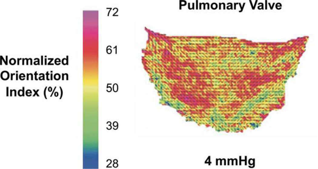
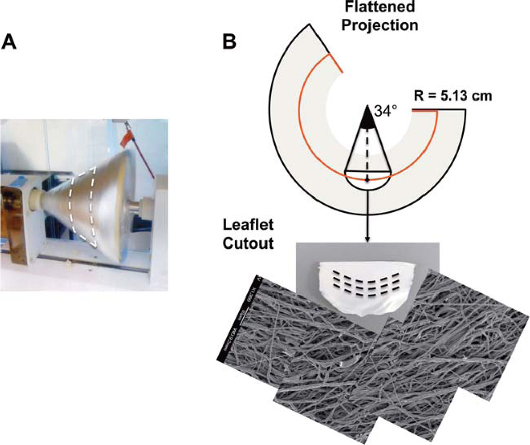
From direct measurements of pulmonary heart valve collagen fiber structure6 a change in angle of alignment of ~34° over the length of the leaflet was observed (Fig. 1). This fiber structure was found to well fit with a circle 5.13 cm in radius. To mimic this structure, conical mandrels of varying pitch angles were designed and fabricated with a 15 cm base so that when projected flat they produced a circle of radius 5.13 cm [Fig. 2(A,B)]. For electrospinning, poly(ester urethane)urea (PEUU; synthesized using previously described methods,15 was dissolved at 12% w/v in 1,1,1,3,3,3-hexafluoroisopropanol (Sigma) and fed through a stainless steel tube (ID = 1.19 mm) at a flow rate of 1.5 mL h−1. The tube was oriented horizontally and perpendicular to the axis of mandrel rotation and charged to 11 kV. The collector mandrel was charged to −5 kV. This mandrel was rotated at 1720 RPM to achieve a tangential velocity at the target radius of 4.5 m s−1 during the electrospinning process, the speed determined to be necessary to induce appropriate fibrous alignment.14 Prior to scaffold removal from the mandrel, a line was drawn on the electrospun mat using a solvent resistant marker to indicate the target radius of 5.13 cm. This line was readily visible under scanning electron microscopy (SEM). To validate that the tangential velocity was the sole variable controlling curvilinear alignment, a second conical mandrel was fabricated with twice the height, and therefore, half of the original opening angle. Electrospinning was performed as described above, again targeted at a radius 5.13 cm. As a control, scaffolds fabricated using a cylindrical mandrel rotated with a tangential velocity of 4.5 m s−1 were also tested.
FIGURE 1.
A. Orientation angle and degree of alignment as measured by small angle light scattering of a human pulmonary valve cusp. Adopted from Joyce et al.6 [Color figure can be viewed in the online issue, which is available at wileyonlinelibrary.com.]
FIGURE 2.
A. Photograph of the conical mandrel during production of curvilinear electrospun sheets. B. Illustration of the flattened, conical electrospun sheet showing a partial circle of radius 5.13 cm which produces curvilinear oriented fibers of the appropriate scale. (Bottom) Image of the excised leaflet and mosaic of scanning electron micrograms taken at 1-mm spacings along the length of the excised scaffold. [Color figure can be viewed in the online issue, which is available at wileyonlinelibrary.com.]
Scanning electron microscopy and structural analysis
For imaging, PEUU scaffolds were Au/Pd sputter coated under vacuum to a thickness of 3.5 nm and mounted with known orientation with respect to original mandrel dimensions. Sets of 19 images were taken at 1 mm spacing along the circumferential direction of the scaffold immediately adjacent to the radius of interest. Structural characterization was completed using a fully automated image analysis program as previously described.16 From each image, the main fiber alignment angle, orientation index (quantification of fiber alignment), fiber diameter, and intersection density were automatically extracted.
Uniaxial and biaxial mechanical testing
For uniaxial testing constructs were sectioned for uniaxial mechanical testing using a dog-bone shaped punch (Ray–Ran Testing Equipment). Sections were cut from each specimen along the radius of interest in both the circumferential direction and radial direction. An MTS Tytron 250 Micro-Force Testing Workstation with a 25 mm min−1 crosshead speed was used to mechanically evaluate each section according to ASTM D638-98. Planar biaxial tests were performed according to established methods.14 Briefly, testing was performed in phosphate buffered saline at room temperature, with test protocols maintained a constant ratio of membrane tension throughout cycling.
Suture retention strength
Two 5 × 15 mm2 strips were sectioned from each scaffold for suture retention testing. Sections were oriented so that one would be cut parallel to the preferred fiber direction and one would be cut perpendicular. These were considered circumferential and radial directions, respectively, as would be appropriate if the constructs were cut into leaflets. Testing was performed according to American National Standard Institute—Association for the Advancement of Medical Instruments (ANSI/AAMI) VP20 standards. A single loop of 4–0 braided polyester suture (Syneture) was placed in each section with a 2 mm bite and then pulled at 120 mm min−1 (MTS Tytron 250 MicroForce Testing Workstation). Suture retention strength was defined as the peak load before pullout/(suture diameter × sample thickness).
Leaflet strain mapping
Electrospun PEUU sheets fabricated on either cylindrical or conical mandrels were cut into the size and shape of human pulmonary valve leaflets and labeled evenly with fiducial markers at an approximate spacing of 2 mm. The electrospun leaflets were then installed in a trileaflet configuration within a mock flow loop developed previously.17 The valve assembly was submerged in a refractive index matching glycerin-water (70:30) solution and transvalvular pressure was quasi-statically increased from 0 to 40 mmHg. Two high-speed cameras (A504k Basler, Germany) were utilized to image surface deformations. Fiducial markers were digitized and used to construct a three dimensional strain map as described previously.18
Statistical analyses
All data were presented as mean ± standard derivation. Statistical significance was determined using one-way analysis of variance (ANOVA) with the Holm–Sidak method for post hoc pairwise comparisons.
RESULTS
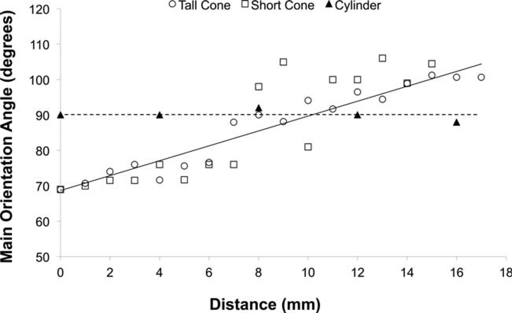
Fabricated scaffolds were found to possess highly anisotropic microstructures. Structural analysis quantified that the fibers that comprised these materials were all highly aligned with an orientation index > 0.6.16 The fibers in scaffolds fabricated using conical mandrels possessed a main angle of alignment that consistently changed along the length of the material by ~1.8° per millimeter (Fig. 3). None of the other structural parameters studied (nodal density, fiber diameter, and branching density) changed along the length of each section. Conversely, as expected, scaffolds fabricated on the cylindrical control mandrel possessed a consistent main angle of alignment along section length.
FIGURE 3.
Quantitative analysis of the change in main angle of alignment versus linear distance on two differently sized conical mandrel and a reference cylindrical mandrel.
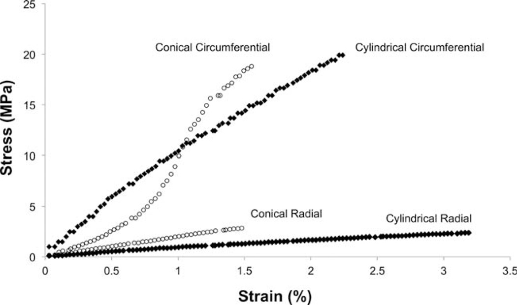
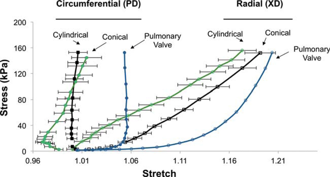
In agreement with previous reports,14 uniaxial mechanical testing demonstrated pronounced differences in mechanical responses between the circumferential and radial axes of constructs fabricated on cylindrical mandrels. Similar behavior was observed from electrospun constructs fabricated on conical mandrels except for a noticeable toe region in the circumferential axis (Fig. 4). This toe region was not apparent in constructs fabricated on a cylindrical mandrel, nor was it apparent in the radial axis of any group studied. No statistically significant difference was observed in suture retention between the circumferential and radial axes of constructs fabricated on the conical mandrel; however the radial (cross-preferred) direction of scaffolds from the cylindrical mandrel possessed higher suture retention strength than for the circumferential direction. Both orientations of every construct evaluated in this study possessed suture retention strength in excess of commercially available ePTFE vascular graft material (23 N mm−2)19 (Table I). Biaxial mechanical testing demonstrated pronounced mechanical anisotropy in all constructs evaluated and no significant difference was found in peak stretches at physiologic loading levels between constructs fabricated on a cylindrical mandrel and those fabricated on a conical mandrel. (Fig. 5) Further, the electrospun constructs were found to have similar mechanical anisotropy to the native pulmonary valve.
FIGURE 4.
Uniaxial stress strain curves from representative constructs produced on cylindrical and conical mandrels.
TABLE I.
Uniaxial Mechanical Properties of Electrospun Scaffolds Fabricated on Conical and Cylindrical Mandrels
| Ultimate Tensile Strength (MPa) |
Breaking Strain (%) |
Suture Retention Strength (N mm−2) |
|
|---|---|---|---|
| Conical mandrel (circumferential) | 16.2 ± 1.6a | 173 ± 18e | 71.4 ± 2.6h |
| Cylindrical mandrel (circumferential) | 12.2 ± 0.9b | 151 ± 22e | 69.4 ± 9.5h |
| Conical mandrel (radial) | 3.3 ± 1.3c | 240 ± 37f | 64.9 ± 6.2h |
| Cylindrical mandrel (radial) | 6.4 ± 1.1d | 431 ± 40g | 102 ± 8.4i |
Significance between groups (p<0.05) within each measured parameter is indicated by a unique letter.
FIGURE 5.
The biaxial mechanical response of scaffolds fabricated on conical and cylindrical mandrels in comparison to native pulmonary valve. All data are presented as mean ± standard deviation where applicable. [Color figure can be viewed in the online issue, which is available at wileyonlinelibrary.com.]
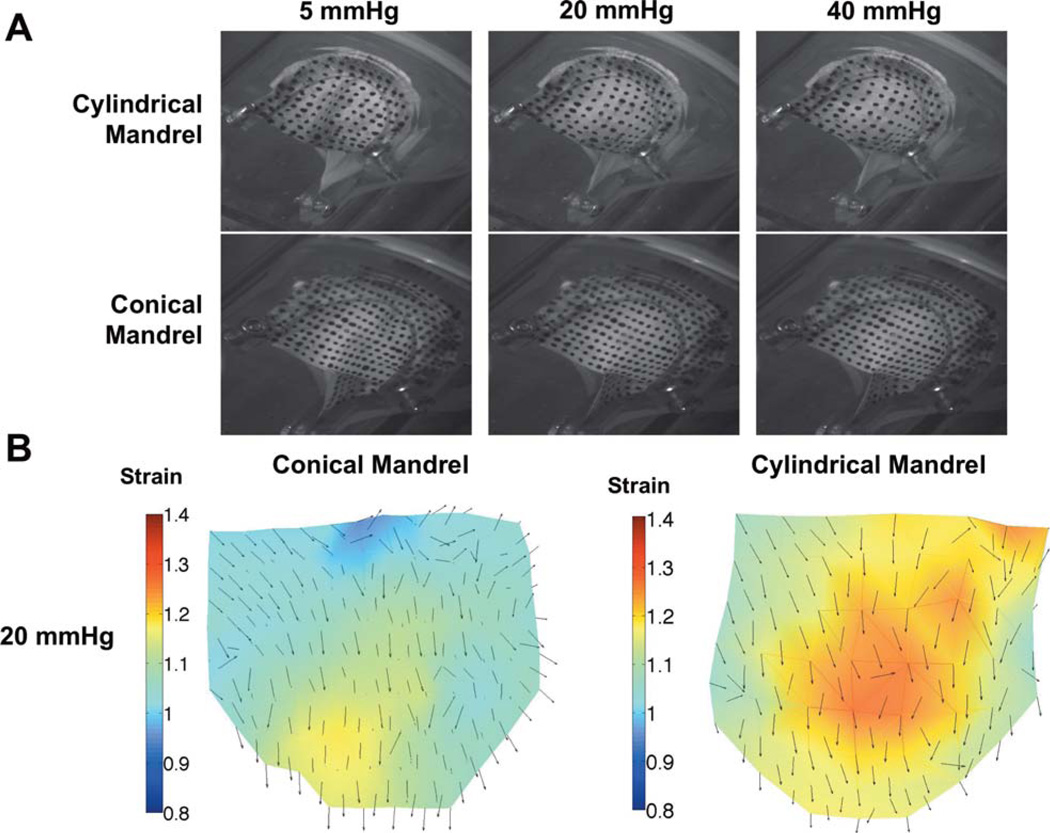
Both linear and curvilinear structured engineered leaflets were found to be capable of full coaptation under minimal physiologic pressure [Fig. 6(A)]. No leaking was observed in either valve. Digital image analysis revealed pronounced differences in the strain maps between the two leaflet groups [Fig. 6(B)]. The leaflets from the cylindrical mandrel exhibited non-uniform strain patterns with localized regions of high strain in the belly region and commissure, while the curvilinear electrospun group experienced lower overall strain and a more uniform strain distribution.
FIGURE 6.
A. Macroscopic images of the two types of scaffolds mounted in a trileaflet orientation under quasi-static loading. (20 mmHg is physiologic loading, 40 mmHg is hyperphysiologic) B. Quantified strain maps derived from quasi-static loading demonstrating a more uniform strain distribution for leaflet scaffolds fabricated with curvilinear fiber geometries. [Color figure can be viewed in the online issue, which is available at wileyonlinelibrary.com.]
DISCUSSION
Previous attempts to fabricate polymeric scaffolds with mechanical behaviors similar to valve leaflets have focused on mimicking organ level mechanical response, and have achieved appropriate levels of planar mechanical anisotropy14 and flexural modulus.20,21 More sophisticated approaches have attempted to better replicate the highly aligned, laminar microstructure by employing hydrogels reinforced with polycaprolactone (PCL),22 poly(glycerol sebacate)/poly(ε-caprolactone),23 or combining electrospinning and microfabrication techniques.24 Nevertheless, these constructs neglect to address larger scale features such as the spatially varying fibrous orientation over the surface of an entire heart valve leaflet. As the field progresses toward whole organ replacement, more complex fabrication techniques may be necessary to expand the design space available at both the microstructural and tissue levels. It was hypothesized that scaffolds with biomimetic curvilinear fiber orientations would eliminate the unnatural strain concentrations predicted to arise from linearly aligned fibers, while maintaining the physiologic mechanical anisotropy necessary for organ level function.
Recently, Fisher et al. reported on a technique for fabricating electrospun scaffolds with curvilinear structures for knee meniscus tissue engineering.25 In that report, the polymer was electrospun onto a disk rotating at high speeds in order to circumferentially align the constituent fibers. However, in utilizing a rotating disk more complex electrospinning modifications such as multiple polymer electrospinning for improved pore size26 or concurrent cell electrospraying may not be as readily implemented due to electrostatic repulsions between electrospinning and electrospraying jets.27
This work presents a different methodology for creating electrospun scaffolds with curvilinear microarchitectures. This was accomplished by electrospinning onto a conical mandrel rotating at a tangential velocity associated with aligned fiber morphologies. Consistent with previous reports,14 scaffolds fabricated in this manner on both cylindrical and conical mandrels were generally mechanically appropriate for cardiovascular biomaterial application and possessed highly anisotropic microstructures as well as planar biaxial mechanics that mimic the anisotropy of the native pulmonary valve at physiological load levels (Fig. 5). Unlike traditional scaffolds fabricated on cylindrical mandrels, the constructs fabricated in this work possessed constituent fibers with a main angle of orientation that changed by 30° along a linear distance consistent with human or ovine valvular geometry (Fig. 3). As predicted by previous structural analysis and modeling,7 localized regions of high strain were observed in linearly aligned leaflets under physiological pressure [Fig. 6(B)]. When implanted in vivo, these localized regions of high strain are potential regions for stress concentration and may trigger failure mechanisms. Further, given the observed difference in regional strains, the mechanical cues transduced to interstitial cells in these two scaffolds is likely quite different. Therefore, employing a curvilinear scaffold in a tissue engineering paradigm may result in improved tissue formation and more homogenous ECM deposition.
Several additional studies will logically follow this work in order to best evaluate this technique for potential use in fabricating engineered heart valve tissue replacements. First, a blood compatibility study could be valuable in determining thrombogenicity and troubleshooting potential issues prior to animal implantations. While it is possible that scaffolds could be infiltrated with cells in vivo, it is likely that a confluent external layer of viable cells, particularly VECs or endothelial progenitor cells, would be of interest. While most of the pertinent features of valve function can be assessed under the quasi-static testing performed here, such as coaptation and surface strains, further studies could also be undertaken with full human pulmonary hemodynamics to assess flexural properties under complex time varying flows. These flexural characteristics may need to be optimized in order to most genuinely reproduce native hemodynamics. Related to this last point, previous work20 has demonstrated methodologies for tuning flexural rigidity in electrospun scaffolds that would be compatible with the fabrication modalities presented.
CONCLUSIONS
A technique for the consistent production of electrospun scaffolds with a curvilinear constituent fiber population was presented. As hypothesized, these biomimetic scaffolds were observed to be free from high strain regions when loaded in a trileaflet assembly under physiologic pressures. Thus, this biomimetic technique for the formation of micro-fibrous tissue engineering scaffolds with controlled curvilinear fiber architecture provides a means to better reproduce salient organ level characteristics of native leaflet structure and function.
Acknowledgments
Contract grant sponsor: NIH; contract grant number: HL-068816
Contract grant sponsor: NIH Biomechanics in Regenerative Medicine T32 Doctoral Training Program; contract grant number: T32 EB 3392-5
REFERENCES
- 1.Ferencz C, Rubin JD, McCarter RJ, Brenner JI, Neill CA, Perry LW, Hepner SI, Downing JW. Congenital heart disease: Prevalence at livebirth. The Baltimore–Washington infant study. Am J Epidemiol. 1985;121:31–36. doi: 10.1093/oxfordjournals.aje.a113979. [DOI] [PubMed] [Google Scholar]
- 2.Vesely I, Boiughner D. Analysis of the bending behaviour of porcine xenograft leaflets and of natural aortic valve material: Bending stiffness, neutral axis and shear measurements. J Biomech. 1989;22:222–227. doi: 10.1016/0021-9290(89)90016-x. [DOI] [PubMed] [Google Scholar]
- 3.Jana S, Tefft BJ, Spoon DB, Simari RD. Scaffolds for tissue engineering of cardiac valves. Acta Biomater. 2014;10:2877–2893. doi: 10.1016/j.actbio.2014.03.014. [DOI] [PubMed] [Google Scholar]
- 4.Mol A, Smits AIPM, Bouten CVC, Baaijens FPT. Tissue engineering of heart valves: Advances and current challenges. Expert Rev Med Dev. 2009;6:259–275. doi: 10.1586/erd.09.12. [DOI] [PubMed] [Google Scholar]
- 5.Sacks MS, Schoen FJ, Mayer JE. Bioengineering challenges for heart valve tissue engineering. Annu Rev Biomed Eng. 2009;11:289–313. doi: 10.1146/annurev-bioeng-061008-124903. [DOI] [PubMed] [Google Scholar]
- 6.Joyce EM, Liao J, Schoen FJ, Mayer JE, Sacks MS. Functional collagen fiber architecture of the pulmonary heart valve cusp. Ann Thorac Surg. 2009;87:1240–1249. doi: 10.1016/j.athoracsur.2008.12.049. [DOI] [PMC free article] [PubMed] [Google Scholar]
- 7.Fan R, Bayoumi AS, Chen P, Hobson CM, Wagner WR, Mayer JE, Sacks MS. Optimal elastomeric scaffold leaflet shape for pulmonary heart valve leaflet replacement. J Biomech. 2013;46:662–669. doi: 10.1016/j.jbiomech.2012.11.046. [DOI] [PMC free article] [PubMed] [Google Scholar]
- 8.Ramaswamy S, Gottlieb D, Engelmayr GC, Aikawa E, Schmidt DE, Gaitan-Leon DM, Sales VL, Mayer JE, Sacks MS. The role of organ level conditioning on the promotion of engineered heart valve tissue development in vitro using mesenchymal stem cells. Biomaterials. 2010;31:1114–1125. doi: 10.1016/j.biomaterials.2009.10.019. [DOI] [PMC free article] [PubMed] [Google Scholar]
- 9.Engelmayr GC, Sales VL, Mayer JE, Sacks MS. Cyclic flexure and laminar flow synergistically accelerate mesenchymal stem cell-mediated engineered tissue formation: Implications for engineered heart valve tissues. Biomaterials. 2006;27:6083–6095. doi: 10.1016/j.biomaterials.2006.07.045. [DOI] [PubMed] [Google Scholar]
- 10.Kim BS, Nikolovski J, Bonadio J, Mooney DJ. Cyclic mechanical strain regulates the development of engineered smooth muscle tissue. Nat Biotechnol. 1999;17:979–983. doi: 10.1038/13671. [DOI] [PubMed] [Google Scholar]
- 11.Lee CH, Shin HJ, Cho IH, Kang YM, Kim IA, Park KD, Shin JW. Nanofiber alignment and direction of mechanical strain affect the ECM production of human ACL fibroblast. Biomaterials. 2005;26:1261–1270. doi: 10.1016/j.biomaterials.2004.04.037. [DOI] [PubMed] [Google Scholar]
- 12.Huey DJ, Athanasiou KA. Tension-compression loading with chemical stimulation results in additive increases to functional properties of anatomic meniscal constructs. PLoS One. 2011;6:e27857. doi: 10.1371/journal.pone.0027857. [DOI] [PMC free article] [PubMed] [Google Scholar]
- 13.De Jonge N, Kanters FMW, Baaijens FPT, Bouten CVC. Strain-induced collagen organization at the micro-level in fibrin-based engineered tissue constructs. Ann Biomed Eng. 2013;41:763–774. doi: 10.1007/s10439-012-0704-3. [DOI] [PubMed] [Google Scholar]
- 14.Courtney T, Sacks MS, Stankus J, Guan J, Wagner WR. Design and analysis of tissue engineering scaffolds that mimic soft tissue mechanical anisotropy. Biomaterials. 2006;27:3631–3638. doi: 10.1016/j.biomaterials.2006.02.024. [DOI] [PubMed] [Google Scholar]
- 15.Guan J, Sacks MS, Beckman EJ, Wagner WR. Synthesis, characterization, and cytocompatibility of elastomeric, biodegradable poly(ester-urethane)ureas based on poly(caprolactone) and putrescine. J Biomed Mater Res. 2002;61:493–503. doi: 10.1002/jbm.10204. [DOI] [PubMed] [Google Scholar]
- 16.D’Amore A, Stella JA, Wagner WR, Sacks MS. Characterization of the complete fiber network topology of planar fibrous tissues and scaffolds. Biomaterials. 2010;31:5345–5354. doi: 10.1016/j.biomaterials.2010.03.052. [DOI] [PMC free article] [PubMed] [Google Scholar]
- 17.Hildebrand DK, Wu ZJ, Mayer JE, Sacks MS. Design and hydrodynamic evaluation of a novel pulsatile bioreactor for biologically active heart valves. Ann Biomed Eng. 2004;32:1039–1049. doi: 10.1114/b:abme.0000036640.11387.4b. [DOI] [PubMed] [Google Scholar]
- 18.Amini R, Voycheck CA, Debski RE. A method for predicting collagen fiber realignment in non-planar tissue surfaces as applied to the glenohumeral capsule during clinically relevant deformation. J Biomech Eng. 2013:1–36. doi: 10.1115/1.4026105. [DOI] [PMC free article] [PubMed] [Google Scholar]
- 19.Lee JC, Peitzman AB. Damage-control laparotomy. Curr Opin Crit Care. 2006;12:346–350. doi: 10.1097/01.ccx.0000235213.63988.9a. [DOI] [PubMed] [Google Scholar]
- 20.Amoroso NJ, D’Amore A, Hong Y, Rivera CP, Sacks MS, Wagner WR. Microstructural manipulation of electrospun scaffolds for specific bending stiffness for heart valve tissue engineering. Acta Biomater. 2012;8:4268–4277. doi: 10.1016/j.actbio.2012.08.002. [DOI] [PMC free article] [PubMed] [Google Scholar]
- 21.Durst CA, Cuchiara MP, Mansfield EG, West JL, Grande-Allen KJ. Flexural characterization of cell encapsulated PEGDA hydrogels with applications for tissue engineered heart valves. Acta Biomater. 2011;7:2467–2476. doi: 10.1016/j.actbio.2011.02.018. [DOI] [PMC free article] [PubMed] [Google Scholar]
- 22.Tseng H, Puperi D, Kim E, Ayoub S, Shah J, Cuchiara M, West J, Grande-Allen K. Anisotropic poly(ethylene glycol)/polycaprolactone hydrogel-fiber composites for heart valve tissue engineering. Tissue Eng Part A. 2014 Oct;20(19–20):2634–2645. doi: 10.1089/ten.tea.2013.0397. [DOI] [PMC free article] [PubMed] [Google Scholar]
- 23.Eslami M, Vrana NE, Zorlutuna P, Sant S, Jung S, Masoumi N, Khavari-Nejad RA, Javadi G, Khademhosseini A. Fiber-reinforced hydrogel scaffolds for heart valve tissue engineering. J Biomater Appl. 2014;29:399–410. doi: 10.1177/0885328214530589. [DOI] [PubMed] [Google Scholar]
- 24.Masoumi N, Annabi N, Assmann A, Larson BL, Hjortnaes J, Alemdar N, Kharaziha M, Manning KB, Mayer JE, Khademhosseini A. Tri-layered elastomeric scaffolds for engineering heart valve leaflets. Biomaterials. 2014;35:7774–7785. doi: 10.1016/j.biomaterials.2014.04.039. [DOI] [PMC free article] [PubMed] [Google Scholar]
- 25.Fisher MB, Henning EA, Söegaard N, Esterhai JL, Mauck RL. Organized nanofibrous scaffolds that mimic the macroscopic and microscopic architecture of the knee meniscus. Acta Biomater. 2012;9:4496–4504. doi: 10.1016/j.actbio.2012.10.018. [DOI] [PMC free article] [PubMed] [Google Scholar]
- 26.Baker BM, Gee AO, Metter RB, Nathan AS, Marklein RA, Burdick JA, Mauck RL. The potential to improve cell infiltration in composite fiber-aligned electrospun scaffolds by the selective removal of sacrificial fibers. Biomaterials. 2008;29:2348–2358. doi: 10.1016/j.biomaterials.2008.01.032. [DOI] [PMC free article] [PubMed] [Google Scholar]
- 27.Seol Y-J, Kim K-H, Kim IA, Rhee S-H. Osteoconductive and degradable electrospun nonwoven poly(epsilon-caprolactone)/CaO-SiO2 gel composite fabric. J Biomed Mater Res A. 2010;94:649–659. doi: 10.1002/jbm.a.32738. [DOI] [PubMed] [Google Scholar]


