Abstract
G protein-coupled receptors (GPCRs) signal primarily through G proteins or arrestins. Arrestin binding to GPCRs blocks G protein interaction and redirects signaling to numerous G protein-independent pathways. Here we report the crystal structure of a constitutively active form of human rhodopsin bound to a pre-activated form of the mouse visual arrestin, determined by serial femtosecond X-ray laser crystallography. Together with extensive biochemical and mutagenesis data, the structure reveals an overall architecture of the rhodopsin-arrestin assembly, in which rhodopsin uses distinct structural elements, including TM7 and Helix 8 to recruit arrestin. Correspondingly, arrestin adopts the pre-activated conformation, with a ~20° rotation between the N- and C- domains, which opens up a cleft in arrestin to accommodate a short helix formed by the second intracellular loop of rhodopsin. This structure provides a basis for understanding GPCR-mediated arrestin-biased signaling and demonstrates the power of X-ray lasers for advancing the frontiers of structural biology.
G protein-coupled receptors (GPCRs) comprise the largest family of cell surface receptors, which signal primarily via G proteins or arrestins1,2. Upon activation, GPCRs recruit heterotrimeric G proteins and subsequently G protein-coupled receptor kinases (GRKs), which phosphorylate GPCRs to allow the high affinity binding to arrestin3. Arrestin binding to the receptors blocks their interactions with G proteins and leads to the receptor’s desensitization4. The binding of arrestins to GPCRs also initiates numerous cellular signaling pathways that are independent of G proteins. Arrestin-mediated signaling is therefore a central component of the GPCR functional network.
GPCRs are targets of one-third of the current clinically used drugs. Recent studies have demonstrated that G-protein and arrestin pathways are distinct and can be pharmacologically modulated independently using biased GPCR ligands, which selectively modulate either G-protein or arrestin pathways5. Biased GPCR ligands are often preferred over unbiased agonists and antagonists, as they selectively direct the receptor to a subset of partners and can deliver therapeutic benefits with fewer undesirable side effects. Research toward biased ligands has become a new trend for GPCR-targeting therapeutics6.
The molecular mechanisms of GPCR signaling have been unraveled by recent breakthroughs in GPCR structural biology7–10. In the antagonist-bound state, GPCRs assume a closed conformation with the cytoplasmic ends of the transmembrane (TM) helices packed closely with each other7,9, thus blocking the interactions with G proteins or arrestins. In contrast, agonist binding promotes conformational changes in GPCRs, including a dramatic movement within the cytoplasmic side of the TM domain8,11–14, thus allowing activated receptors to recruit G proteins or arrestins to mediate downstream signaling. However, arrestin coupling to GPCRs may require a conformation of the receptor different from that required for coupling with G proteins14,15.
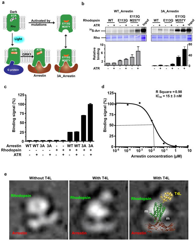
Rhodopsin is a prototypical GPCR responsible for light perception7. Along with β2AR, rhodopsin has served as a model system for studying GPCR signaling16. Figure 1a shows rhodopsin binding to G protein and arrestin. Light induces isomerization of 11-cis-retinal to all-trans-retinal (ATR), which activates rhodopsin and promotes its interactions with G protein17,18. Light-activated rhodopsin is then phosphorylated by rhodopsin kinase (GRK1), leading to high affinity recruitment of arrestin that terminates the G protein signaling. Activation of rhodopsin can also be achieved through mutations, including the E1133.28Q /M2576.40Y mutation, which yields a constitutively active rhodopsin19 (Superscripts in residues refer to the Ballesteros-Weinstein numbering20). The crystal structure of bovine rhodopsin has been determined in the inactive, resting state7, the ligand-free state21,22, and the ligand-activated state in complex with a G protein peptide23. Arrestin structures have also been determined in the inactive24,25 and pre-activated form1,2. Recent electron microscopy (EM) analysis has revealed the assembly and conformational dynamics of the β2AR-β-arrestin complex26. Here we report the crystal structure of an active form of human rhodopsin bound to a pre-activated mouse visual arrestin, determined by serial femtosecond crystallography (SFX). The structure has been confirmed by EM, double electron-electron resonance (DEER), hydrogen-deuterium exchange mass spectrometry (HDX), cell-based rhodopsin-arrestin interaction assays, and site-specific disulfide cross-linking experiments. Our study provides a molecular basis for understanding GPCR-mediated arrestin-biased signaling.
Figure 1. Rhodopsin-arrestin interactions and complex assembly.
a, Diagram of the binding of rhodopsin (Rho) with G-protein and arrestin as described in the main text. Labels are 11-cis retinal (ECR) and all-trans-retinal (ATR).
b, Rhodopsin and arrestin interaction determined by pull-down assay in the absence and presence of ATR (top panel). Middle panel: rhodopsin loading controls. Bottom panel: Relative binding of 35S-labelled arrestin was determined by densitometry (n=3, error bars=SD).
c, Binding of His8-MBP-rhodopsin (E1133.28Q /M2576.40Y) protein to biotin-MBP-arrestin (WT and 3A) measured by AlphaScreen in the absence or presence of 5 μM ATR. The first six columns are controls (luminescence signals in the presence of only one of the binding partners; n=3, error bars=SD).
d, Competition of arrestin binding to rhodopsin was determined by a homologous AlphaScreen assay and the IC50 value was derived from repeat experiments (n=3, error bars=SD).
e, Negative stain EM images of rhodopsin-arrestin complexes without or with T4L at the N-terminus; Right panel: Overlay of the EM image with the structures of T4L, rhodopsin and arrestin. m: detergent micelle.
Characterization and crystallization of the rhodopsin-arrestin complex
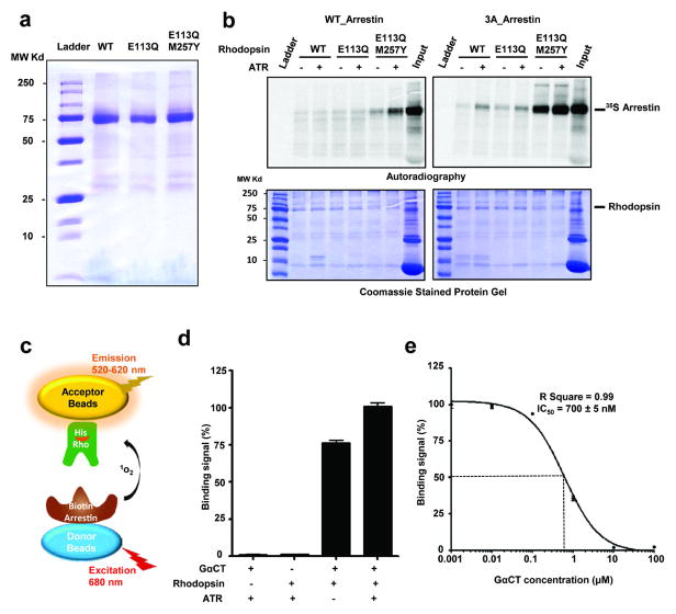
To characterize the rhodopsin-arrestin interaction, we expressed and purified E1133.28Q and E1133.28Q/ M2576.40Y mutant receptors (Extended Data Fig. 1a). These mutations were introduced in the context of the N2NtermC/N282ECL3C mutant that is known to create a disulfide bond that increases rhodopsin stability without affecting its activity27–29. The N2NtermC/N282ECL3C mutant is referred to as our wild type (WT) control. To determine the interaction between rhodopsin and arrestin, we developed a bead binding pull-down assay. In this assay, rhodopsin expressed as a fusion with a maltose-binding protein (MBP) at its N-terminus was bound to amylose beads, which were then used to pull down in vitro translated arrestin labeled with 35S. Figure 1b shows that WT arrestin has weak background binding to WT rhodopsin. The E1133.28Q mutation increased WT arrestin binding by 2–3 fold, and the E1133.28Q /M2576.40Y mutation further increased the binding of WT arrestin in the presence of all-trans-retinal (4–8 fold). In contrast to the relatively weak binding of WT arrestin, the binding of 3A_arrestin, a pre-activated form of arrestin that obviates the need for receptor phosphorylation for high affinity binding through three alanine mutations in L374, V375, and F376 in the C-terminal tail of arrestin, is much stronger. In the absence of all-trans-retinal, we observed a nearly 30-fold increase of 3A_arrestin binding to the E1133.28Q /M2576.40Y receptor. All-trans-retinal further increased 3A_arrestin binding to the E1133.28Q /M2576.40Y receptor by ~60-fold above the binding of WT arrestin to WT rhodopsin (Fig. 1b and Extended Data Fig. 1b).
We also measured rhodopsin-arrestin interactions using AlphaScreen assays (Extended Data Fig. 1c) with His8-tagged rhodopsin and biotin-tagged arrestin. WT arrestin interacted weakly with the E1133.28Q /M2576.40Y rhodopsin, regardless of the presence of all-trans-retinal (Fig. 1c). As a positive control, the GαCT peptide, a high affinity peptide variant of the C-terminus of G-transducin (Gt)30, readily interacted with the E1133.28Q /M2576.40Y receptor in the absence of all-trans-retinal, and addition of all-trans-retinal slightly increased this interaction (Extended Data Fig. 1d). Quantitative competition using unlabeled 3A_arrestin or GαCT with the E1133.28Q /M2576.40Y receptors revealed an IC50 value of 15 nM and 700 nM for the binding of 3A_arrestin and the GαCT peptide, respectively (Fig. 1d and Extended Data Fig. 1d). The strength of the interaction between the E1133.28Q /M2576.40Y rhodopsin and the 3A_arrestin is in a similar range as the estimated Kd value of 30–80 nM for the binding of arrestin to the fully activated phosphorylated rhodopsin31.
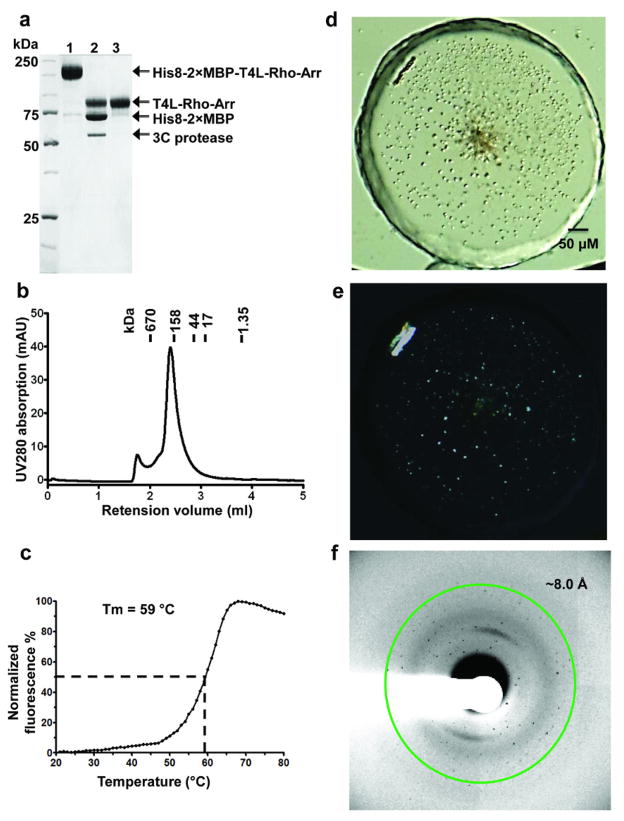
Mixing individually purified proteins did not yield a stable 1:1 complex, nor did it lead to crystallization. Extensive biochemical data support a 1:1 stoichiometry in the rhodopsin-arrestin complex32,33. Therefore, we engineered a fusion protein in which 3A_arrestin is linked by a 15-residue linker to the C-terminus of E1133.28Q /M2576.40Y rhodopsin. We expressed and purified the rhodopsin-arrestin fusion protein, as well as a T4 lysozyme (T4L)-rhodopsin-arrestin fusion, in which a T4L is fused to the N-terminus of rhodopsin to increase the soluble surface for crystallization (Extended Data Fig. 2a). The T4L-rhodopsin-arrestin fusion protein is monomeric and relatively stable with a Tm of 59 °C (Extended Data Fig. 2b–c). Negative stain EM images revealed that E1133.28Q /M2576.40Y rhodopsin and 3A_arrestin form a stable complex with arrestin bound to the cytoplasmic side of rhodopsin (Fig. 1e). The T4L-rhodopsin-arrestin fusion protein formed crystals with sizes in the range of 5 to 15 μm under various lipid cubic phase (LCP) crystallization conditions (Extended Data Fig. 2d–e). Despite extensive optimization, the crystals diffracted only to 6–8 Å at synchrotron sources (Extended Data Fig. 2f). We thus turned our attention to the emerging method of SFX34 with an LCP injector (LCP-SFX)35,36.
Structure determination by serial femtosecond crystallography
Because of the small size of crystals, we hypothesized that diffraction by X-ray free electron laser (XFEL) would improve data quality given the advantages of intense and very short XFEL pulses for micrometer-size crystals. In the LCP-SFX method, a stream of gel-like LCP with fully hydrated microcrystals runs continuously in vacuum across the 1.5 μm-diameter XFEL beam, which delivers 120 X-ray pulses per second with less than 50 fs pulse duration and sufficient intensity to capture crystal diffraction patterns with a single pulse. Within ~12 h of run time, we collected over 5 million detector frames, of which 22,262 had more than 40 diffraction spots as determined by the Cheetah hit-finding software37. Diffraction patterns from 18,874 crystals could be indexed and integrated using CrystFEL38. The data were processed according to the apparent point group of 4/mmm with a large unit cell (a=b=109.2 Å and c=452.6 Å). The diffraction was anisotropic with resolution limits of 3.8 Å and 3.3 Å along the a*/b* and c* axes, respectively (Supplementary Table 1a and Fig. 5).
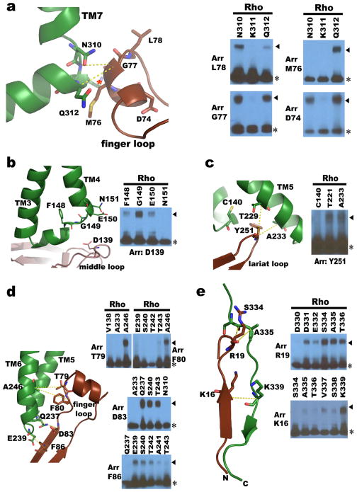
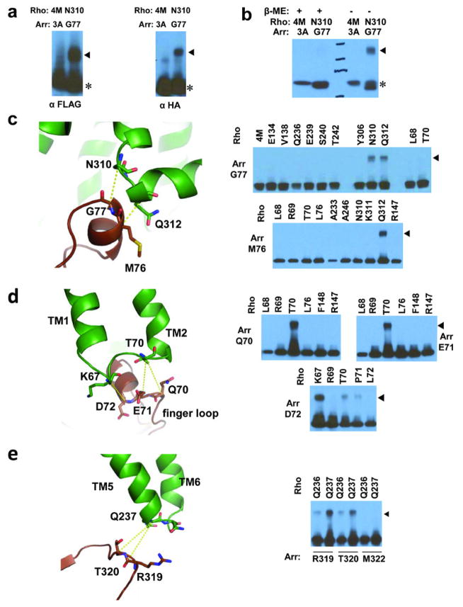
Figure 5. Validation of the rhodopsin-arrestin interface by disulfide bond cross-linking.
a–e, Structure and cross-linking of arrestin with rhodopsin. Panels are arrestin finger loop with rhodopsin TM7 and helix 8 (a); arrestin middle loop with rhodopsin ICL1 (b); arrestin lariat loop residue Y251 with rhodopsin TM5 (c); arrestin β-strand interface residues with residues of rhodopsin TM5, ICL3, and TM6 (d); and arrestin’s N-terminus with rhodopsin’s C-tail (e). Rhodopsin K311 is marked with a red star and arrestin M76 is show in full for clarity. Part of the computational model for the full rhodopsin-arrestin complex was used in panel (e).
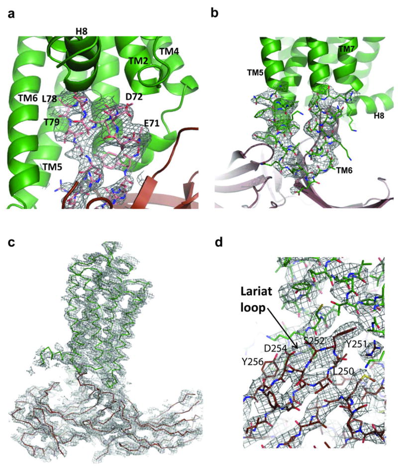
The crystals appeared to be pseudo-merohedrally twinned in P212121 (Supplementary Table 2) and the structure was solved by molecular replacement using known structures of active rhodopsin39 and pre-activated arrestin1 (Details in methods). The structure contains four rhodopsins (residues 1–326), four arrestins (residues 12–361 with a small missing loop of residues 340–342), and three T4Ls (residues 2–161 in complexes A and D; residues 2–12 and 58–162 in complex C; no T4L was modeled in Complex B due to poor density) (Figure 2). The final structure was refined to Rwork and Rfree of 25.2% and 29.3%, respectively, with excellent geometry (Supplementary Table 1b). The overall arrangement of the T4L-rhodopsin-arrestin complex is well supported by the electron density maps (Extended Data Fig. 3), including a 3000 K simulated annealing omit map. Because of the twinned nature of the datasets, we performed extensive structure-validation experiments, including DEER, HDX, cell-based rhodopsin-arrestin interaction assays and site-specific disulfide cross-linking. Below we describe the rhodopsin-arrestin structure and the results of validation experiments.
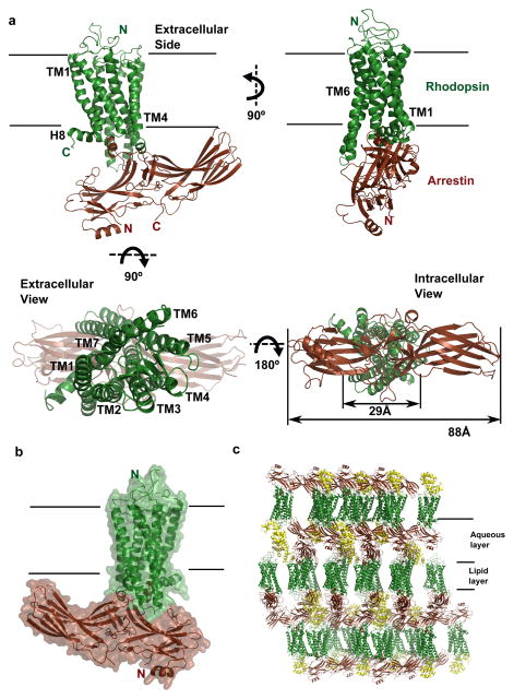
Figure 2. The structure of the rhodopsin-arrestin complex.
a, The structure of the rhodopsin-arrestin complex in four orientations. The relative dimensions of rhodopsin and arrestin are shown in the intracellular view. TM1-TM7 indicates rhodopsin transmembrane helices 1–7; H8 is intracellular Helix 8.
b, An overall view of the rhodopsin-arrestin complex shown with transparent solid surface. T4 Lysozyme (T4L) is omitted from this view.
c, Crystal packing diagram of the rhodopsin-arrestin complex with T4L as yellow ribbon model.
Overall structure of the rhodopsin-arrestin complex
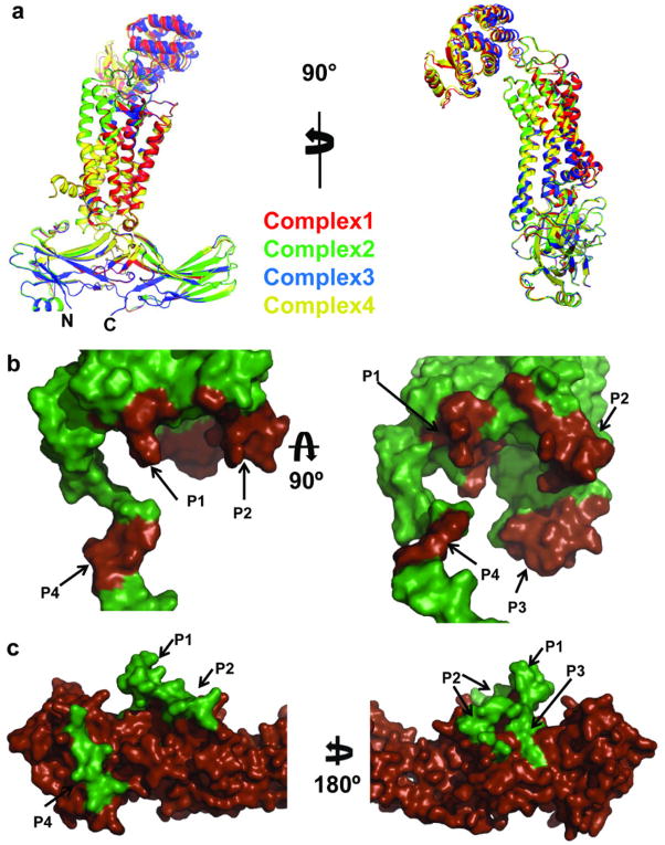
The most striking feature of the rhodopsin–arrestin complex is the asymmetric binding of arrestin to rhodopsin (Fig. 2) and this asymmetric arrangement is similar in all four complexes in the asymmetric unit, providing an independent confirmation of the rhodopsin-arrestin complex assembly (Extended Data Fig. 4). Figure 2a shows one rhodopsin-arrestin complex in four 90° orientations. From the intracellular (IC) view, rhodopsin and arrestin have similar heights, but the width of arrestin is nearly three times that of rhodopsin. Figure 2b shows the rhodopsin–arrestin complex in a transparent surface, whose overall arrangement of the domains can be fit into the EM images (Fig. 1e). Figure 2c shows the layered or Type I packing of the complex in the crystal lattice with alternating hydrophilic and hydrophobic layers comprising arrestin, T4L, and rhodopsin, respectively (Fig. 2c). This arrangement allows the complex to form extensive packing interactions that involve all soluble portions of the proteins, with the arrestin being the central mediator for packing with T4L, rhodopsin, and arrestin from neighboring symmetry related molecules.
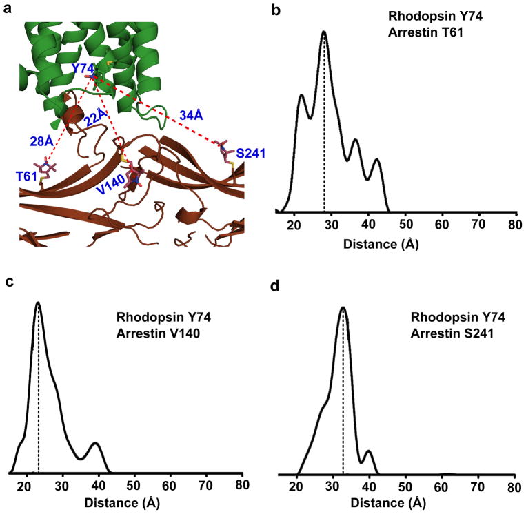
To validate the assembly of the rhodopsin-arrestin complex, we used DEER to determine intermolecular distances within the complex40. The DEER distances from residue Y742.41 of rhodopsin to three arrestin residues (T61, V140, and T241) measured in a non-fused rhodopsin-arrestin complex were 28 Å, 23 Å and 33 Å, closely matching the distances of 28 Å, 22 Å, and 34 Å, respectively, as observed in the crystal structure (Fig. 3). The intramolecular distances in the active arrestin bound to light-activated phosphorylated rhodopsin have also been studied extensively by DEER41, and all of them match exceedingly well with the crystal structure (Supplementary Table 3). Together, these data support that the complex formed by fusion proteins closely resembles the physiologically relevant complex formed by individual proteins.
Figure 3. DEER validation of rhodopsin-arrestin complex assembly.
a, An overall view of rhodopsin-arrestin assembly showing the three intermolecular distances based on the models of the R1 nitroxide pairs at rhodopsin residue Y742.41 and three arrestin residues T61, V140, and S241 based on the crystal structure.
b–d, The experimental distance distributions between the nitroxide spin labeled R1 pairs of rhodopsin Y742.41 and bovine arrestin S60, V139, and L240, which are in equivalent positions to mouse arrestin T61(b), V140 (c), and S241(d) as labeled in the figure. Y axes are the probability of distance distribution.
The rhodopsin-arrestin interface
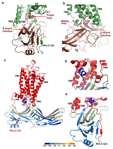
The four rhodopsin-arrestin complexes in the asymmetric unit adopt nearly identical interfaces (Extended Data Fig. 4a), which are stabilized by intermolecular interactions as summarized in Supplementary Table 4. The total surface area buried in the interface is 1350 Å2, which is substantially smaller than the area (2576 Å2) buried in the β2AR-Gs complex8. Unlike the continuous interface observed in the β2AR-Gs complex, the rhodopsin-arrestin complex has four distinct arrestin interface patches (Fig. 4a–b and Extended Data Fig. 4b). The first arrestin interface patch consists of the finger loop (residues Q70 to L78), which adopts a short α-helix and forms extensive interactions with the C-terminus of TM7 and the N-terminus of Helix 8, as well as the loop residues (ICL1) of rhodopsin. Interactions of arrestin with TM7 of rhodopsin are of particular interest because conformational changes in TM7 have been implicated in arrestin-biased signaling14,15. Moreover, the close interactions between rhodopsin’s Helix 8 and arrestin have been shown to be essential for high-affinity binding of arrestin to the activated rhodopsin42. The second arrestin interface patch is formed by the middle loop (residue V140 region) and the lariat loop (residue Y251 region) that interact with the ICL2 of rhodopsin, and the arrestin back loop (R319 and T320) that interacts with the C-terminus of TM5. The middle and lariat loops are close to each other in the inactive arrestin, but move apart upon its activation to form a cleft that accommodates the ICL2 of rhodopsin, which adopts a short helix (Fig. 4a–b). The positions of the finger loop and the lariat loop are supported by a composite omit 2Fo-Fc electron density map (Extended Data Fig. 3d). The third arrestin interface patch is the β-strand (residues 79–86), which follows the finger loop and interacts with residues from TM5, TM6 and ICL3 of rhodopsin. The fourth arrestin putative interface patch is mostly between its N-terminal β-strand (residues 11–19) and the C-terminal tail of rhodopsin, which was not visible in the electron density map due to the apparent flexibility of this region but was computationally modeled based on HDX and disulfide cross-linking data described below (Extended Data Fig. 5). Consistent with the crystal structure, these arrestin elements have been implicated in various aspects of arrestin activation and receptor binding43,44.
Figure 4. The rhodopsin-arrestin interface and its validation by HDX.
a–b, Two overall views showing the four interface patches of the rhodopsin-arrestin complex.
c–d, Mapping of HDX on the rhodopsin-bound arrestin structure. Rhodopsin is colored in red and arrestin is colored based on the exchange rate differences between free 3A_arrestin and rhodopsin-bound arrestin as shown in Extended Data Fig. 6a. This figure was made using a computational model of the full rhodopsin-arrestin complex.
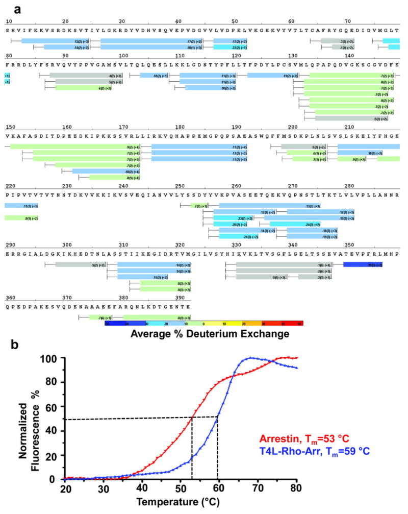
To further characterize the rhodopsin-arrestin interfaces, we performed three additional sets of validation experiments. The first was HDX, which probes the dynamics and stability of protein complexes45. Compared with free arrestin, the rhodopsin-bound arrestin has several regions that are protected from exchange, including the finger loop and the N-terminal β-sheets, consistent with their location in the rhodopsin-binding interface (Fig. 4c–d, and Extended Data Fig. 6a). The hydrogen to deuterium exchange rate of arrestin in the complex is lower than that for free arrestin across the whole protein, indicating that arrestin is stabilized by complex formation, consistent with the results of previous HDX experiments46 and thermal stability assays, which revealed that the melting temperature of free arrestin is six degrees lower than that of the complex (53 ° C vs. 59 ° C, Extended Data Fig. 6b).
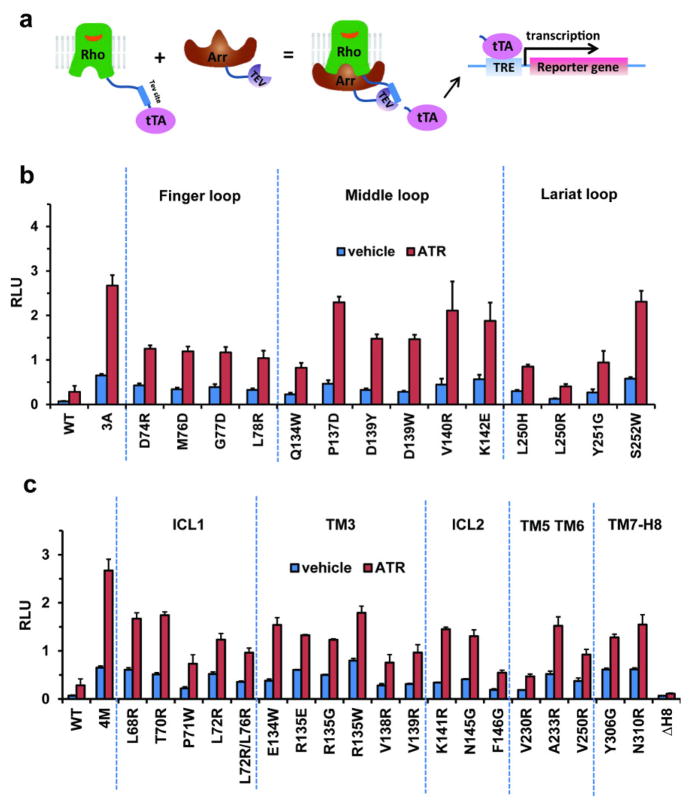
The second set consisted of Tango assays47, which have been used for probing GPCR-arrestin interactions (Extended Data Fig. 7a). WT rhodopsin and WT arrestin had a very low basal interaction and all-trans-retinal increased the binding by ~3-fold. In contrast, E1133.28Q /M2576.40Y rhodopsin showed a high level of interaction with the pre-activated 3A_arrestin, and addition of all-trans-retinal further increased the binding signal by ~5-fold. Mutations in finger loop (D74, M76, G77, and L78), middle loop (Q134 and D139), and lariat loop (L250 and Y251) decreased rhodopsin-arrestin binding (Extended Data Fig. 7b). Correspondingly, mutations in rhodopsin residues involved in arrestin binding also weakened the interaction (Extended Data Fig. 7c), consistent with the complex crystal structure.
The third set consisted of site-specific disulfide cross-linking experiments, which have been used to validate structures based on the geometry requirements for disulfide bond formation (Cα –Cα distances of 5–9 Å and appropriate side-chain orientations). We engineered cysteine pairs at the binding interface of arrestin and rhodopsin, which were tagged with FLAG and HA, respectively. Over 314 co-expression combinations were tested and monitored by SDS-PAGE followed by Western blotting (Extended Data Fig. 8). The results are summarized in Supplementary Table 5. Every interface residue in arrestin was included in the study and the results closely agree with the crystal structure. For example, the distances from the Cα atom of the finger loop residue G77 of arrestin to the Cα atoms of N3107.57, K3118.48 and Q3128.49 in rhodopsin fit the requirement for disulfide bond formation (Fig. 5a). G77C cross linked efficiently with N3107.57C and Q3128.49C, but not with K3118.48 C because the Cβ of K3118.48 points away from G77 (Fig. 5a). Neither did G77C show cross-linking with a large set of other rhodopsin residues, indicating the high specificity of the cross-linking experiments (Extended Data Fig. 8c and Supplementary Table 5). In contrast, several other mutants in the finger loop region (D74C, M76C, and L78C) readily cross-linked with Q3128.49C from Helix 8 (Fig. 5a). The cross-linking results of these four finger loop residues not only matched the crystal structure, but also agreed well with the results from the Tango assays (Extended Data Fig. 7b). In addition, mutants of three N-terminal finger loop residues (Q70C, E71C, and D72C) were cross-linked to mutants in rhodopsin ICL1 T70ICL1C and K67ICL1C, respectively (Extended Data Fig. 7d).
We also observed cross-linking of the arrestin middle loop (D139) with rhodopsin ICL2 (G149ICL2) (Fig. 5b); of the arrestin lariat loop (Y251) with rhodopsin TM5 (T2295.64 and A2335.68) (Fig. 5c); of the arrestin β-strand (residues 79–86) that follows the finger loop with rhodopsin TM5, TM6, and ICL3 (Fig. 5d). Additional cross-linking was observed in two back-loop residues R319C and T320C of arrestin with Q237ICL3C of TM5 in rhodopsin (Extended Data Fig. 8e). Furthermore, extensive crosslinking of the arrestin N-terminus with the C-terminal tail of rhodopsin was detected, including R19 of arrestin with S334Cterm of rhodopsin (Fig. 5e), K16 of arrestin with S338Cterm and K339Cterm of rhodopsin, and V11 and S10 of arrestin with the final eight residues of rhodopsin (Supplementary Table 5). Together, these cross-linking experiments further validated the interface assembly of the rhodopsin-arrestin complex.
Possible structural mechanisms for biased signaling: G protein vs. arrestin
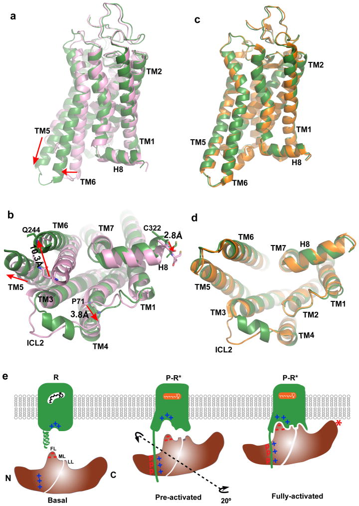
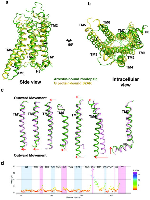
The rhodopsin-arrestin complex represents the first crystal structure of a GPCR bound to arrestin and provides an opportunity to examine the mechanism of arrestin-biased signaling. Although a crystal structure of G protein-bound rhodopsin is not available, a number of rhodopsin structures bound to GαCT have been determined11,23,39 and reveal that the arrangement of TM helices in light-activated rhodopsin is similar to that in the G protein-bound β2AR complex, with the exception of TM6, whose outward movement in β2AR is much more pronounced upon binding to G protein8. The arrestin-bound rhodopsin has its intracellular end of TM6 moved outward by ~10 Å relative to its inactive structure (Fig. 6a–b and Extended Data Fig. 9). This is in contrast to the 14 Å outward movement of TM6 reported in the G protein-bound β2AR complex8. Compared to the GαCT-bound rhodopsin11, arrestin-bound rhodopsin has additional conformational differences in TM1, TM4, TM5, and TM7 (Fig. 6c–d and Extended Data Fig. 9), and these unique structural features may constitute essential elements for arrestin-biased signaling.
Figure 6. Structural basis of arrestin-biased signaling and arrestin recruitment.
a–b, Two views of structural overlays of arrestin-bound rhodopsin (green) with inactive rhodopsin (pink).
c–d, Two views of structural overlays of arrestin-bound rhodopsin (green) with GαCT peptide-bound rhodopsin (orange).
e, A cartoon model of arrestin recruitment by a phosphorylated and active rhodopsin. In the dark state, the receptor is inactive (R-state) and arrestin is in the closed state (basal state). Receptor activation and phosphorylation (P-R* state) allow the phosphorylated C-terminal tail of rhodopsin to bind to the N-domain of arrestin (pre-activated state), thus displacing the arrestin C-terminal tail. This displacement destabilizes the polar core of arrestin, which allows a 20° rotation between the arrestin N- and C- domains, leading to the opening of the middle loop (ML) and lariat loop (LL) to accommodate the ICL2 helix of rhodopsin (fully-activated state). The activated receptor also opens the cytoplasmic side of the TM bundle to adopt the finger loop (FL) of arrestin.
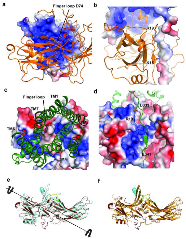
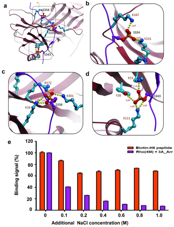
The molecular assembly observed in the rhodopsin-arrestin complex also provides a general model for arrestin recruitment by phosphorylated rhodopsin-like class A GPCRs. In the computational model of the full complex, the highly cationic N-terminal domain of arrestin is paired with the C-terminal tail of rhodopsin (Extended Data Fig. 10). Based on the extensive disulfide crosslinking data and computation modeling, phosphorylated S334, S338 and S343 can form tight ionic interactions with three positively charged pockets at the N-terminus of arrestin (Extended Data Figure 11a–d). These results support a model of arrestin activation by phosphorylated rhodopsin through the C-tail exchange mechanism (Fig. 6e)2. The displacement of the arrestin C-terminus by the phosphorylated rhodopsin C-tail destabilizes the polar core of arrestin48, thus allowing for a 20° rotation of the N- and C- domains of arrestin that opens a cleft between the middle and lariat loops into which the ICL2 helix of rhodopsin can fit. The ionic interaction between rhodopsin and arrestin is consistent with the fact that it is highly salt sensitive in our AlphaScreen assay (Extended Data Fig. 11e), in agreement with the salt sensitive binding of phosphorylated rhodopsin to arrestin43,48. Importantly, the cytoplasmic face of the rhodopsin TM bundle is highly positively charged whereas the finger loop (residues 70–78) contains three conserved negatively charged residues (E71, D72, and D74) (Extended Data Fig. 10). Thus, the interaction of arrestin with the rhodopsin TM bundle is mediated not only by shape but also by charge complementarity. Arrestins are highly conserved with only four subtypes in vertebrates. In contrast, there are hundreds of GPCRs, with cytoplasmic interfaces that are largely non-conserved. However, the positive charge property is widely presented on the cytoplasmic side of a number of GPCR structures (Extended Data Fig. 12). Electrostatic interactions between arrestins and GPCRs may represent an adaptive mechanism for arrestins to pair promiscuously with the large number of GPCRs.
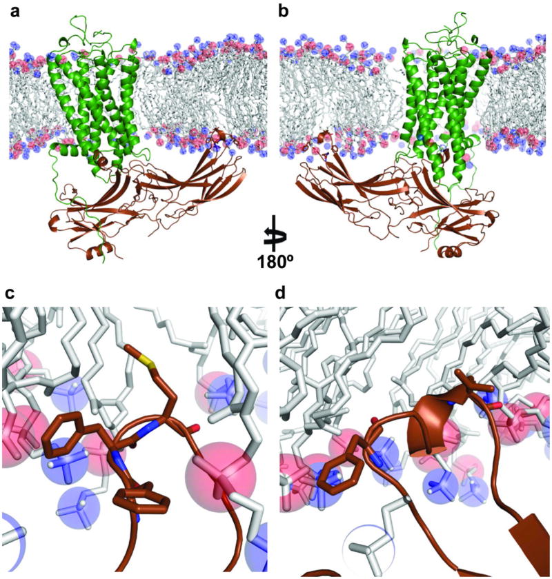
The asymmetric orientation of the bound arrestin with regard to the relative positions of its N-C domains in respect to the membrane has important implication in its binding to rhodopsin (Fig. 2a–b). Such asymmetric assembly brings the arrestin C-domain toward the membrane, with the C-edge either being touched or embedded in the membrane layer (Extended Data Figure 13). The C-edge is comprised of conserved hydrophobic residues (F197, F198, M199, F339, and L343). It has been puzzling why single alanine mutations at these residues would affect arrestin binding to rhodopsin given how far away they are from the receptor43. The close proximity of these hydrophobic residues to the lipid membrane may provide an explanation for the effects of their mutations on binding to rhodopsin. GPCR signaling regulator proteins are normally membrane associated through lipid modifications, as is the case for GRK1 and the G-protein subunits Gα and Gβγ. Yet, there is no known lipid modification for any of the arrestins. We speculate that the conserved hydrophobic patch at the C-edge of arrestin may function as a lipid-interacting module that helps to stabilize its interaction with the receptor. Furthermore, one primary function of arrestin is to mediate endocytosis of ligand-activated GPCRs and the highly asymmetric nature of the arrestin assembly may facilitate the membrane curvature for subsequent endocytotic processes. Alternatively, the remote C-edge could serve as the binding site of the second rhodopsin, which has been proposed to form dimers in the rod outer-segment disc membrane49.
LCP-SFX is a new technology that has been used to determine several crystal structures35,36,50. Rhodopsin-arrestin is a challenging membrane protein complex and obtaining a structure of this complex at a sufficiently high resolution was an intractable task using existing methods that include synchrotron-based crystallography and cryo-EM26. The rhodopsin-arrestin complex structure reported here demonstrates the utility of the X-ray lasers when combined with SFX and an LCP crystal delivery system35. The SFX method is relatively new and under continuous development. Given its success in solving the rhodopsin-arrestin structure, we expect that X-ray lasers, with further method development, will continue to provide breakthrough insights into biology and chemistry.
Methods
Protein Preparation
We used human rhodopsin and mouse visual arrestin-1 in this study. The T4L-rhodopsin-arrestin fusion protein was expressed using a tetracycline-inducible expression cassette encoding a fusion protein with His8-MBP-MBP followed by a 3C protease cleavage site at the N-terminus of the T4L-rhodopsin-arrestin. In this engineered construct, we have fused a cysteine-free T4L (residues 2–161 with C54T and C97A) to the N terminus of a rhodopsin that contains four mutations: N2NtermC and N282ECL3C to form a disulfide bond, and E1133.28Q and M2576.40Y for constitutive receptor activity. The C terminus of rhodopsin was fused to 3A_arrestin (L374A, V375A, F376A, residues 10–392) with a 15 amino acid linker (AAAGSAGSAGSAGSA).
The fusion protein constructs were expressed in HEK293S cells (Invitrogen) transiently transfected using Lipofectamine 2000 (Invitrogen). Cells were transfected at a density of 2×10⁶ cells/ml at a 100 ml scale in SFM4TransFx-293 (HyClone). Six hours post transfection, cells were diluted ten-fold with CDM4HEK293 medium (HyClone). When the cell density reached approximately 4×10⁶ cells/ml, protein expression was induced by the addition of doxycycline to a final concentration of 1 μg/ml. After 24 h induction, cells were harvested, resuspended in hypotonic buffer (20 mM HEPES-Na, pH 7.5, 10 mM NaCl, 10 mM MgCl2) supplemented with EDTA-free protease inhibitor cocktail (Roche), followed by Dounce homogenization. The lysate was centrifuged at 45,000 rpm at 4 °C for 1 h. Then membranes were solubilized in 20 mM Tris-HCl, pH 7.4, 100 mM NaCl, 10% glycerol, 0.5% (w/v) n-dodecyl-β-D-maltopyranoside (DDM, Anatrace), 0.1% (w/v) cholesteryl hemisuccinate (CHS, Anatrace), and protease inhibitor cocktail for two hours at 4 °C. The supernatant was isolated by centrifugation at 45,000 rpm for one hour, and incubated with amylose beads (New England Biolabs) at 4 °C overnight. Typically 10 ml of resin were used for supernatant from one liter of the original cell culture. The resin was washed with 200 ml of washing buffer (10 mM Tris-HCl, pH 7.4, 100 mM NaCl, 0.005% (w/v) lauryl maltose neopentyl glycol (MNG-3, Anatrace), 0.001% (w/v) CHS) and the protein was eluted with washing buffer containing 10 mM maltose. The eluted fusion protein was concentrated to 40–50 mg per 1 ml and the His8-MBP-MBP tag was cleaved by overnight incubation with 3C protease at 4 °C. The cleaved His8-MBP-MBP tag was removed by incubating with 300 μl Ni2+-NTA beads (Qiagen) for three hours at 4 °C. The purified T4L-rhodopsin-arrestin was collected and concentrated to 30 mg/ml for crystallization.
WT rhodopsin and rhodopsin mutants E1133.28Q and E1133.28Q /M2576.40Y used for MBP pull-down and AlphaScreen assays were expressed from the same vector with His8-MBP tag at the N-terminus. Protein expression and purification were similar as for the rhodopsin-arrestin fusion protein used for crystallization, with the difference that proteins were not eluted, but remained bound to beads.
To generate biotinylated proteins for the AlphaScreen assays, WT and 3A_arrestin (residues 10–392) open reading frames were cloned with N-terminal avitag-MBP tag into the first expression cassette of a modified pET-Duet expression vector (Novagen), and the biotin ligase gene BirA was cloned into the second cassette. The 14 amino acid avitag contains a single lysine that is efficiently biotinylated in vivo by BirA protein51. BL21 (DE3) cells transformed with the expression plasmid were grown in LB broth at 16 °C to an OD600 of ~1.0 and induced with 0.1 mM IPTG in the presence of 40 μM biotin for 16 h. Cells were harvested, resuspended in 50 ml extraction buffer (20 mM Tris-HCl, pH 8.0, 150 mM NaCl, and 10% glycerol) per two liters of cells, and passed three times through a French Press with pressure set at 1000 Pa. The lysate was centrifuged at 16,000 rpm in a Sorvall SS-34 rotor for 30 min, and the supernatant was loaded on a 5 ml amylose HP column (GE Healthcare). The column was washed with 100 ml of wash buffer (20 mM Tris-HCl, pH 8.0, 150 mM NaCl, and 10% glycerol) and eluted in buffer containing 20 mM Tris-HCl, pH 8.0, 150 mM NaCl and 20 mM maltose. The eluted biotin-MBP-arrestin was concentrated and further purified by size exclusion chromatography through a HiLoad 16/60 Superdex 200 column (GE Healthcare) in 20 mM Tris-HCl, pH 8.0, and 150 mM NaCl. Monomeric protein was collected for further assay.
Untagged 3A_arrestin (residues 10–392) was expressed as a His6-SUMO fusion protein from the expression vector pSUMO (LifeSensors). The expression and purification of untagged arrestin followed the same method as for biotin-MBP-arrestin, except that the His6-SUMO tag was cleaved overnight with SUMO protease52 at a protease/protein ratio of 1:1000 in the cold room.
MBP pull-down assay
Arrestin was cloned into the pCITE-4a vector (Novagen) to allow for transcription from a T7 promoter. The TNT Quick Coupled Transcription and Translation kit was used according to the manufacturer’s protocol (Promega), to express 35S-methionine-labelled WT arrestin and 3A_arrestin (L374A, V376A, and F376A). Radiolabelled WT arrestin and mutant arrestin proteins were incubated with His8-MBP-rhodopsin fusion protein immobilized to 50 μl of maltose agarose bead suspension. Proteins and beads were incubated at 4 °C for one hour on a rotating platform in binding buffer containing 20 mM Tris-HCl, pH 7.4, 100 mM NaCl and 0.02% DDM/0.004% CHS. The beads were then washed three times with binding buffer and resuspended in 400 μl elution buffer (20 mM Tris-HCl, pH 7.4, 100 mM NaCl, 0.02% DDM/0.004% CHS and 100 mM maltose). The eluates were concentrated and incubated at room temperature for 15 minutes with 2 × loading dye. Samples were separated on 12% sodium dodecyl sulfate (SDS)-denaturing polyacrylamide gels. Gels were stained with Coomassie R-250, dried at 70 °C for 90 minutes, and exposed overnight to a phosphor storage screen. Results were visualized on a PhosphorImager (Fuji).
Assays for the interactions between rhodopsin and arrestin or G protein peptide
Interactions between rhodopsin and arrestin were assessed by luminescence-based AlphaScreen assay (Perkin Elmer), which our group has used extensively to determine ligand-dependent protein-protein interactions of nuclear receptors. The AlphaScreen principle is illustrated in Fig. 1c. Briefly, biotinylated arrestin was bound to streptavidin-coated donor beads and His8-tagged rhodopsin was bound to nickel-chelated acceptor beads. The donor and acceptor beads were brought into close proximity by the interactions between rhodopsin and arrestin, which were measured in the presence or absence of all-trans-retinal (Sigma). When excited by a laser beam of 680 nm, the donor bead emits singlet oxygen that activates thioxene derivatives in the acceptor beads, which releases photons of 520–620 nm as the binding signal. The experiments were conducted with 100 nM of rhodopsin and arrestin proteins in the presence of 5 μg/ml donor and acceptor beads in a buffer of 50 mM MOPS-Na, pH 7.4, 50 mM NaF, 50 mM CHAPS, and 0.1 mg/ml bovine serum albumin. The results were based on an average of three experiments with standard errors typically less than 10%. GαCT (TGGRVLEDLKSCGLF) and biotinylated GαCT were synthesized by Peptide 2.0. For the competition assay, different amounts of untagged arrestin or GαCT were added to the reaction to compete with tagged arrestin or GαCT for rhodopsin binding.
Thermal stability assay
The thermal stability assay was performed with the thiol-specific fluorochrome N-[4-(7-diethylamino-4-methyl-3-coumariny)phenyl]maleimide (CPM) as described previously53. Briefly, 10 μg of protein was diluted with dilution buffer (20 mM Tris-HCl, pH 7.5, 200 mM NaCl, 0.005% MNG-3/CHS) to 195 μl, while CPM dye stock (4 mg/ml in DMSO) was freshly diluted to 0.2 mg/ml in the dark. After 5 min of incubation at room temperature for both protein and CPM dye separately, 5 μl of diluted CPM dye was added to the protein sample and the protein/dye mix transferred immediately into a sub-micro quartz fluorometer cuvette (Starna Cells) and measured in a Cary Eclipse spectrofluorometer (Agilent). Assays were performed from 20 °C to 80 °C with a slope of 2 °C increase per minute at an excitation wavelength of 387 nm and an emission wavelength of 463 nm. All data were processed using GraphPad Prism and fit using the Boltzmann sigmoidal equation to determine the melting temperature (Tm) as inflection point of the melting curves.
Crystallization
T4L-rhodopsin-arrestin crystals were grown in lipid cubic phase (LCP)54. Protein solution (~30 mg/ml) was mixed with monopalmitolein (9.7 MAG, from Nu-Chek Prep, Inc) containing 10% cholesterol at a 1:1 ratio (w/w) using a coupled syringe mixer55 and 50 nl boluses of protein-laden LCP were dispensed on 96-well glass sandwich plates (Molecular Dimensions or Marienfeld-Superior) and overlaid with 0.8 μl precipitant solutions using a Gryphon LCP robot (Art Robbins Instruments) or an NT8-LCP robot (Formulatrix). Multiple initial hits were identified by using screens of 30% PEG 400 in combination of 100 mM or 400 mM salts from the StockOptions Salt kit (Hampton Research)56. Crystals that reached full size (around 10–20 μm) within four days at 20 °C were harvested from the mesophase and were flash frozen in liquid nitrogen without additional cryoprotectant. Crystals used for synchrotron data collection were grown in 0.05 M magnesium acetate, 0.05 M sodium acetate, pH 5.0 and 28% PEG 400. Crystals for LCP-SFX were prepared in 100 μL gas-tight Hamilton syringes as described36,57. About 5 μl of protein-laden LCP in the presence of 5-fold molar excess of all-trans-retinal was slowly injected into 60 μl mother liquid buffer (0.15 M ammonium phosphate, pH 6.4 and 32% PEG 400) using a coupled syringe mixing device55. Crystals were grown in several syringes at 20 °C, consolidated and transferred into the LCP injector35 for XFEL diffraction data collection. The average crystal size was 5–10 μm as determined under a polarized light microscope. The phase diagram for 9.7 MAG suggests that this MAG is a suitable host lipid for extruding LCP in vacuum at 20 °C, where evaporative cooling created problems when 9.9 MAG was used as a host LCP lipid35.
Data collection (Synchrotron)
A partial 8.0 Å synchrotron dataset was collected at 100 K using an X-ray beam at the wavelength of 1.0 Å at the 21 ID-D beam line of LS-CAT and at 23-ID-D of GM-CAT at the Advanced Photon Source at Argonne National Laboratory. A full 7.7 Å dataset was collected from a single crystal (~20 microns in size) using 10 μm beam size and 0.1 s exposures per 0.1° oscillation with a Pilatus 6M pixel detector at the X10SA beam line at the Swiss Light Source. The observed reflections were reduced, merged, and scaled with XDS58 with statistics shown in Supplementary Table 1a. The L-test plot of the 7.7 Å dataset produced a curve that fits a perfectly twinned crystal.
Data collection (XFEL)
LCP-SFX experiments were carried out at the Coherent X-ray Imaging (CXI) instrument59 at the Linac Coherent Light Source (LCLS) in the SLAC National Accelerator Laboratory (Menlo Park, California, USA). X-ray pulses of 50 fs duration at a wavelength of 1.3 Å (9.5 keV) were attenuated to ~3% (3·1010 photons/pulse) and focused to ~1.5 μm diameter at the interaction point using Kirkpatrick-Baez mirrors60. Rhodopsin-arrestin complex crystals in LCP were injected across the XFEL beam using an LCP injector35 with a 50 μm diameter nozzle at a flow rate of ~0.2 μL/min. Diffraction patterns were collected at 120 Hz using the Cornell-SLAC Pixel Array Detector (CSPAD). Over 5 million data frames were collected corresponding to ~12 hours of data acquisition time. Of these frames, ~0.45% images contained potential crystal hits as identified using Cheetah61 (more than 40 Bragg peaks of 1–20 pixels in size and a signal to noise ratio better than 6 after local background subtraction). Of the potential crystal hits, 18,874 diffraction patterns could be auto-indexed by CrystFEL38 using a combination of MOSFLM62, XDS58 and DirAx63. An integration radius of only two pixels was used to avoid overlapping with neighboring peaks due to the high spot density resulting from the large unit cell dimensions. Partial reflections from different crystals in random orientations were merged using a Monte Carlo integration across the crystal rocking curve of each reflection64. The resolution was anisotropic with ~3.3 Å resolution along the c*-axis and ~3.8 Å resolution along the a*/b* axes. The data used for the structure refinement were truncated at 3.8Å/3.8Å/3.3Å using the get_hkl program of CrystFEL38 based on the criteria of data correlation coefficient (CC*), which is 0.87 at the highest resolution shell (Supplementary Table 1a). The use of CC* of 0.5 as resolution cutoff has been recently recommended for X-ray diffraction65. The resolution cutoff for several published XFEL structures follows this criterion, including the 5HT2B GPCR XFEL structure36, which has a CC* of 0.74. The statistics of the final data used in structure refinement are shown in Supplementary Table 1b.
Structure determination
The XFEL data were initially merged according to the apparent Laue group of 4/mmm, and molecular replacement searches were performed in all possible space groups of 4/m and 4/mmm. The best structure solution was found in P43. Based on analysis of the Zanuda program66, we determined that the most likely space group was P212121 and that the crystals were physically twinned. The data were reprocessed with the Laue group of mmm and molecular replacement searches were performed in P212121. This space group assignment resulted in the best statistics and map quality out of several possibilities of space groups (Supplementary Table 2).
The crystals appeared to be pseudo-merohedrally twinned based on L-test analysis67. Despite the challenge of twinned data, the rhodopsin-arrestin complex structure was solved by the molecular replacement method implemented in Phaser68 using the models of constitutively active rhodopsin, pre-activated arrestin, and T4L (PDB codes: 4A4M39, 4J2Q1, and 3SN68, respectively). Four molecules of rhodopsin and four molecules of arrestin were found sequentially by molecular replacement search, resulting in four very similar rhodopsin-arrestin assemblies. Four T4Ls were also found in the aqueous layer with its C-terminal residue in a position to form a covalent bond with the first residue of rhodopsin, supporting the correct positioning of T4Ls by molecular replacement.
The structure was initially refined against the XFEL data without twin law to an Rfree-factor of ~36% and the model maps from the data were of sufficient quality to interpret the overall structure of the rhodopsin-arrestin complex (Extended Data Fig. 3). The model then underwent iterated cycles of manual building into 2Fo-Fc maps with Coot69 and refinement with REFMAC70 and the PHENIX71, where rigid body, individual position, group B-factor, and TLS refinements were used along with NCS restraints and twin law (k, h, -l). The arrestin residues 70–78 and 165–175, which were not included in the molecular replacement model, were manually placed into the density map. These two regions of arrestin became visible because they are either engaged in direct interaction with rhodopsin or involved in crystal packing. Regions with poor density were removed from the final model, including T4L from the B complex and the N-domain of T4L (residues 13–57) from the C complex. We did not observe clear electron density for the all-trans retinal, which was thus not included in the structure. The structure has been carefully refined to the final state that has excellent geometry and refinement statistics (Supplementary Table 1b). Ramachandran plot analysis indicates that 100% of the residues are in favorable or allowed regions (no outliers). The final structure was validated with MolProbity, which revealed an all-atom-clash score of 1.47 and MolProbity score of 1.1372.
The real-space correlation coefficients against a 2mFo-DFc map for each chain of the structure on a per residue basis using the CCP4 EDSTATS program73 or the MolProbity program in Phenix indicated an overall good fit between the structure and the electron density map. The density fit correlation in Coot was low with the structure from Phenix twinned refinement because the map from the MTZ file with map coefficients produced by phenix.refine was not in absolute scale. This problem was overcome by using the 2Fo-Fc CNS format map from phenix.refine, which generated a normal correlation in Coot, similar to those from EDSTATS and MolProbity. All structural figures were prepared using PyMOL74.
Cell-based assays for rhodopsin-arrestin interactions (Tango Assays)
For the cell-based Tango assay47, we generated fusion constructs consisting of rhodopsin (1–321), a tobacco etch virus (TEV) protease cleavage site (TEV site), and the transcriptional activator tTA (Rho-TEV site-rTA) as well as of arrestin (10–392) and TEV protease (Arr-TEV protease). HTL cells were a gift from Dr. Barnea and Dr. Axel (Brown University and Columbia University). 10 ng Rho-TEV site-tTA construct were transfected together with 10 ng Arr-TEV protease plasmid and 1 ng of phRG-tk Renilla luciferase expression vector into HTL cells using Xtremgene (Roche). One day after transfection, cells were induced by vehicle (DMSO) or all-trans-retinal (10 μM) overnight. Cells were harvested and lysed in Passive Lysis Buffer (Promega). Luciferase activity was measured using the Dual Luciferase Kit (Promega) according to manufacturer’s instructions.
Mutagenesis
Site-directed mutagenesis was carried out using the QuickChange method (Agilent). Mutations and all plasmid constructs were confirmed by sequencing prior to protein expression, MBP-pull down assay, Tango assay, and AlphaScreen assay.
EM studies of the rhodopsin-arrestin complex
Samples were prepared as previously described75. Briefly, the sample was applied to a freshly glow-discharged carbon coated copper grid and allowed to adhere for 10 seconds before being reduced to a thin film by blotting. Immediately after blotting 3 μl of a 1% solution of uranyl formate was applied to the grid and blotted off directly. This was repeated three times. Data were acquired using a Tecnai F20 Twin transmission electron microscope operating at 200 kV, with a dose of ~40 e−/Å2 and nominal underfocus ranging from 2 to 3 μm. Images were automatically collected at a nominal magnification of 62,000 × and pixel size of 0.273 nm. All images were recorded with a Tietz F416 4k × 4k pixel CCD camera utilizing Leginon data collection software76. Experimental data were processed by the Appion software package77, which interfaces with the Leginon database infrastructure. ~6000 particles were automatically extracted from 54 EM-micrographs78 and the particle stack was then aligned and sorted using the XMIPP reference-free maximum likelihood alignment79. Several exemplary 2D averages are shown in Figure 1e, which were derived from class averages for the complex with or without T4L, computed from ~14000 particles selected from 155 EM-micrographs.
In-cell disulfide bond cross-linking
The open reading frames of full-length arrestin with C-terminal FLAG tag and full length rhodopsin with C-terminal HA tag were cloned into pcDNA6. Cysteine mutations (41 for arrestin and 51 for rhodopsin) were systematically introduced into arrestin and rhodopsin in these two DNA vectors. AD293 cells were split one day before transfection at 50,000 cells/well in a 24-well plate. Cells were grown for one day, then transfected with 100 ng rhodopsin constructs (pcDNA6-rho-3HA) plus 100 ng arrestin plasmid (pcDNA6-Arr-3FLAG) by Lipofectamine 2000 (DNA/Lipofectamine 2000 ratio of 1:2) in each well. Cells were grown for 2 days after transfection, and were then treated at room temperature with H2O2, which was freshly diluted in the cell culture medium to a final concentration of 1 mM. After 5 min treatment with H2O2, the medium was aspirated and 100 μl of CelLytic M (Sigma C2978) were added to each well and the plate was shaken for 10 min at room temperature. Cell lysates were transferred to 1.5 ml tubes and spun at 16,000 x g at 4 °C for 5 min. The supernatants (10 μl) were mixed with an equal volume of 2×SDS loading buffer (without reducing agents) for 5 min at room temperature, and loaded onto a protein gel for Western blot analysis. HRP-conjugated anti-FLAG (Sigma M2) and anti-HA (Sigma) antibodies were used to probe for free and cross-linked arrestin and rhodopsin proteins.
Hydrogen-Deuterium Exchange Mass Spectrometry (HDX)
HDX was carried out as described previously80, with the following modifications: 1) the solution handling and mixing was performed with a LEAP Technologies Twin HTS PAL liquid handling robot housed inside a temperature-controlled cabinet held at 4 °C and 2) decyl maltose neopentyl glycol (DMNG) was used in place of DDM in the exchange buffer. Briefly, all stock solutions and dilutions were made using the 7TM HDX buffer (50 mM HEPES (pH 7.5), 150 mM NaCl, 2% (v/v) glycerol, 0.01% (m/v) CHS and 0.05% (m/v) DMNG in either H2O or in D2O for on-exchange). All HDX protein stock solutions were prepared at 15 μM in the 7TM HDX H2O buffer. On-exchange was carried out in triplicate for predetermined times (10, 30, 60, 900 and 3600 sec) at 4 °C by mixing 5 μL of stock protein solution with 20 μL of D2O on-exchange buffer. Exchange was quenched by adding 25 μL of quench solution (100 mM NaH2PO4, 0.02% DMNG, and 15 mM TCEP at pH 2.4) to the reaction. Digestion was performed in line with chromatography using an in-house packed pepsin column. Peptides were captured and desalted on a C8 trap. Peptides were then separated across a 5 μ 10×1 mm Betasil C8 column (Thermo Fisher Scientific) with a linear gradient of 12–40% acetonitrile in 0.3% formic acid over a short 5 min gradient to limit back exchange with the solvent.
Mass spectra were acquired in the range of m/z 300–2000 at a resolution of 60,000 for 8 min in positive ion mode on a Q Exactive mass spectrometer (Thermo Fisher Scientific) equipped with an ESI source operated at a capillary temperature of 225 °C and spray voltage of 3.5 kV. The intensity weighted average m/z value (centroid) of each peptide’s isotopic envelope was calculated with the Workbench program81 and converted to % deuterium values. Back-exchange correction was based on an estimated 70% deuterium recovery and accounting for the known 80% deuterium content of the on-exchange buffer. The Workbench software used P-values lower than 0.05 for two consecutive time points to determine significance. Sequence coverage experiments for these proteins were carried out in the 7TM HDX buffer and LC system described above, but with a longer 60 min gradient. 75 pmol of protein were loaded onto the column. For sequencing, tandem mass spectra were obtained using data-dependent acquisition with 30 second dynamic exclusion, where the top five most abundant ions in each scan were selected and subjected to CID fragmentation. Each scan was the average of 3 microscans under normal scan mode in both MS and MS/MS. Peptides were identified by searching spectra against an in-house database using the mascot search engine as described previously45.
Generation of a stable cell line expressing bovine rhodopsin mutant Y74C/C140S/C316S and rhodopsin preparation
The rhodopsin mutant Y74C/C140S/C316S gene82 was PCR-amplified from the pMT vector by using two flanking primers containing NheI and NotI restriction sites and subcloned into vector PB-T-PAF83. The insert in the resulting plasmid termed PB-Rho-Y74C was verified by automated DNA sequencing.
HEK293S GnTI− cells84 were cultured in DMEM/F12 (Wisent) supplemented with 10% heat inactivated FBS (Life Technologies) and 100 U/ml penicillin/streptomycin (Life Technologies) and incubated at 37 °C, 5% CO2. For transfection, cells were plated in 6-well plates at a density of ~600,000 cells per well. The following day, cells were co-transfected with 4 μg of PB-Rho-Y74C, 0.5 μg of PB-RB83 and 0.5 μg of pCyL4383,85 using JetPrime (PolyPlus) reagent following the manufacturer’s instructions and medium was replaced by fresh medium 4 hours later. (Plasmids PB-T-PAF and PB-RB were provided by James Rini, University of Toronto, Canada, and pCyL43 by the Wellcome Trust Sanger Institute, UK). Two days after transfection, cells were transferred to a 100-mm tissue culture plate. Dual drug selection was started the following day, using 10 μg/ml puromycin (Bioshop) and 5 μg/ml blasticidin (Bioshop) and lasted for 2 week. Cells were then transferred to larger flasks and finally to pleated roller bottles (Thermo Scientific) containing 250 ml of DMEM/F12 supplemented with 10% heat inactivated FBS and 100 U/ml of penicillin and streptomycin. Roller bottles were incubated at 37 °C, 5% CO2 and rotated at 0.1 rpm. Expression was induced after 5–6 days by replacing medium with 250 ml of fresh medium containing 1 μg/ml doxycycline (Bio Basic) and 1 μg/ml aprotinin (Bioshop). On day 3 after induction, cells were harvested, using PBS-EDTA with protease inhibitor tablet (Roche) to detach cells. Cell pellets were flash frozen in liquid nitrogen and stored at −80°C until purification.
For purification, cell pellets with rhodopsin mutant Y74C/C140S/C316S were incubated with 11-cis retinal to reconstitute rhodopsin which was purified and spin labeled with 1-oxyl-2,2,5,5-tetramethyl-3-pyrroline-3-methyl methanethiosulfonate (MTSSL) as previously described41.
Incorporation of Spin Labeled Rhodopsin into Nanodiscs
Nanodiscs were prepared by mixing cholate solubilized lipid (70% POPC + 30% POPS), scaffolding protein MSP1E3D186, and rhodopsin (in 90 mM β-OG) in a molar ratio of 140:1:0.1. The OG and cholate were removed from the mixture by dialysis against buffer D (20 mM MOPS, 150 mM NaCl, pH 6.8). The nanodiscs were further purified by passing them over a nickel NTA column to remove any receptor not incorporated into the discs. Upon elution from the nickel column with imidazole, the nanodiscs were buffer exchanged into buffer D containing 10% glycerol.
Spin Labeling of Arrestin Mutants
C-terminally truncated mutants of arrestin, lacking endogenous cysteines, have been shown to bind to non-phosphorylated rhodopsin87. Single-cysteine mutants in this background were expressed in E. coli, as described88, spin labeled in buffer D overnight using a 10-fold molar excess of MTSSL. The base mutant also contained two alanine substitutions (F85A and F197A) which have been shown to disrupt arrestin-1 oligomerization88. Non-covalently bound spin label was removed from the sample by extensive washes with buffer D using Amicon 10 kDa concentrators.
DEER Spectroscopy of the rhodopsin-arrestin fusion complex
Preparations of rhodopsin (Y742.41C) and bovine arrestin (S60C, V139C, and L240C, which correspond to the mouse arrestin T61C, V140C, and T241C) and their spin labelling were performed as described previously41. For DEER measurements, the spin-labeled proteins were mixed in 1:1 ratio in the dark and loaded into quartz capillaries (1.5 mm ID and 1.8 mm OD). The samples were irradiated for 30 sec within the capillaries using a tungsten light source with a 500 nm cutoff filter. Immediately after irradiation, the samples were flash frozen in liquid nitrogen, and loaded into an EN 5107D2 resonator for Q band DEER measurements. Measurements were performed at 80K on a Bruker Elexsys 580 spectrometer with a Super Q-FTu Bridge. A 36-ns π-pump pulse was applied to the low field peak of the nitroxide field swept spectrum, and the observer π/2 (16 ns) and π (32 ns) pulses were positioned 50 MHz (17.8 G) upfield, which corresponds to the nitroxide center line. Model-free distance distributions were obtained from the raw dipolar evolution data using the LabVIEW (National Instruments) program “LongDistances” that can be downloaded from http://www.biochemistry.ucla.edu/biochem/Faculty/Hubbell/.
To estimate the median distances, the distance distributions were integrated and normalized to the maximum amplitude. The median distance was estimated as that corresponding to 0.5 of the integrated intensity. The modeled distances between nitroxide spinlabels are based on the crystal structure of the rhodopsin-arrestin complex. R1 nitroxide sidechains were modeled into the structure using common R1 rotamers89,90.
9.7 MAG/Water Temperature-Composition Phase Diagram
The phase diagram was constructed based on small- and wide-angle X-ray scattering measurements made in the heating direction. Sample preparation and X-ray scattering measurements and analysis were as previously described55,91. The phases identified include the lamellar crystalline (Lc) or solid phase, the fluid isotropic (FI) or liquid phase, and the following liquid crystalline phases: lamellar liquid crystal (Lα), cubic-Ia3d and cubic-Pn3m. A separate aqueous phase observed in equilibrium with the solid or liquid crystalline phases is indicated by Aq. The phase diagram shows that the solid Lc phase stabilizes under equilibrium conditions below ~8 °C. The latter is some 10 °C below that observed with 9.9 MAG (monoolein)91 and is similar to what was found with 7.9 MAG92. This low solidification temperature enabled use in the current project of 9.7 MAG as a host lipid for LCP-SFX data collection in an evacuated sample chamber at 20 °C, where evaporative cooling created problems for measurements with 9.9 MAG but not with 7.9 MAG35. The maximum water carrying capacity of 9.7 MAG resides at ~50 %(w/w) water, which is considerably greater and smaller than that of 9.9 MAG91 and 7.7 MAG93, respectively. These observations indicate that the cubic mesophase of 9.7 MAG has larger aqueous channels compared to 9.9 MAG that are more like those of 7.7 MAG. This is consistent with 9.7 MAG supporting the growth of rhodopsin-arrestin-T4L crystals where the complex has sizable extra-membrane bulk best accommodated in a large aqueous channel. This parallels the observations made with 7.7 MAG as a host lipid for the β2AR-Gs complex structure determination8.
Molecular Modeling of the Full Length Rhodopsin-Arrestin Complex
Energy-based conformational modeling of the rhodopsin-arrestin complex was performed with the ICM-Pro molecular suite 94, using a global energy optimization procedure similar to the one described recently for modeling of the full-length complex of CRFR195. Protein sequences of human rhodopsin and mouse arrestin were obtained from the Uniprot database (http://www.uniprot.org/). Starting from the crystallographically determined structure of the complex, the modeling procedure was used to add unresolved residues of the C-terminus (residues 327–345) of the human rhodopsin structure, as well as missing residues in the arrestin loop (residues 340–342) of the mouse arrestin structure. The final model did not include the last 3 residues of rhodopsin (346–348), which lack well defined crosslinking contacts and appear flexible. Initial conformations of the short loop in arrestin were predicted with the fast “build model” ICM algorithm, followed by extensive energy optimization in internal coordinates. Conformational optimization of the rhodopsin C-terminal peptide was guided by soft pairwise harmonic distance restraints derived from disulfide crosslinking data. The restraints introduced between Cβ atoms of the crosslinked residues were graded according to the crosslinking strength listed in Supplementary Table 5, from very strong, with the penalty function starting at 5 Å distance, to medium at 7 Å distance and very weak at 12 Å. The C-terminal peptide conformation and conformation of the contact side chains of the arrestin were optimized to convergence (3 independent simulations of 106 steps) using global optimization procedure in internal coordinates with improved conformational energy terms for protein and peptides 96. A special backbone closure sampling procedure was applied to the loop regions to allow efficient optimization. The global optimization runs were executed in parallel on a Linux multicore server resulting in similar best energy conformations (<3 Å RMSD; root mean squared deviation) for the C-terminal peptide residues.
The best energy-optimized conformation of this region suggests that the extended C-terminus peptide runs antiparallel along the N-terminal β-strand of arrestin. This conformation of the C-terminus satisfied all 17 medium to strong disulfide crosslinking restraints for this region (Supplementary Table 5), while making a number of specific polar interactions and salt bridges of D331, E332 and E341side chains with arrestin basic residues (Extended Data Figure 5). These modeling results suggest that though the rhodopsin C-terminus is rather flexible, some low energy conformations may be preferable even in non-phosphorylated rhodopsin. Moreover, independent modeling of the complex with phosphorylated serine residues Ser334, Ser338 and Ser343 in the C-terminus of rhodopsin resulted in a similar conformation of this domain. The interactions within phosphorylated complex, however, are greatly enhanced by as many as seven additional salt bridges between negatively charged phosphates and the positively charged lysine and arginine residues within the N- terminal domain of arrestin (Extended Data Figure 11).
Extended Data
Extended Data Fig. 1. Constitutively active rhodopsin interacts with arrestin and GαCT.
a. SDS-PAGE of N-terminally MBP-tagged WT and mutant rhodopsin.
b. Non-cropped versions of the pull-down assay gels shown in Fig. 1B. The interactions between mouse WT arrestin and human WT or E1133.28Q rhodopsin are very weak. In contrast, the interaction between constitutively active rhodopsin (E1133.28Q /M2576.40Y) and pre-activated L374A/V375A/F376A arrestin (3A_arrestin) is strong and is further increased in the presence of 10 μM all-trans retinal. Input: 5% of the binding reaction. Bottom panels show the rhodopsin loading controls.
c, Schematic representation of the AlphaScreen assay.
d. AlphaScreen binding assay between E1133.28Q /M2576.40Y rhodopsin and GαCT (TGGRVLEDLKSCGLF) in the presence and absence of 5 μM all-trans retinal. The two left columns show the controls with “peptide only” and “rhodopsin only”. (n=3, error bars=SD).
e. Determination of the affinity of the interaction between rhodopsin E1133.28Q /M2576.40Y and GαCT by homologous competition. His6 -MBP-rhodopsin mutant protein was immobilized on Ni-acceptor beads and biotinylated GαCT on streptavidin donor beads. Binding between rhodopsin and arrestin brings donor and acceptor beads into close proximity, resulting in the indicated binding signal. Non-biotinylated GαCT competed for the interaction with an IC50 of ~700 nM (n=3, error bars=SD).
Extended Data Fig. 2. Purification and crystallization of T4L-rhodopsin-arrestin.
a, Purification of the T4L-rhodopsin-arrestin (T4L-Rho-Arr) complex. His8-MBP-MBP-T4L-Rho-Arr complex was first purified by amylose column chromatography (lane1). The His8-MBP-MBP tandem tag was then released by cleavage with 3C protease (lane 2) and removed by binding to Ni-NTA beads to recover pure T4L-rhodopsin-arrestin (T4L-Rho-Arr) protein (lane 3).
b, Analytical gel filtration profile of the T4L-rhodopsin-arrestin complex. T4L-rhodopsin-arrestin eluted mostly as monomers with a small proportion of oligomers. The molecular weights of protein standards are indicated at the top.
c, Thermal stability shift analysis of T4L-rhodopsin-arrestin. T4L-rhodopsin-arrestin is relatively stable with a Tm of 59 °C.
d, Crystals of T4L-rhodopsin-arrestin in lipidic cubic phase under bright field illumination (top) and polarized light (bottom).
e, X-ray diffraction pattern of a T4L-rhodopsin-arrestin crystal recorded at LS-CAT of APS. The green ring indicates the position of reflections at 8.0 Å resolution.
Extended Data Fig. 3. Electron density map for the overall complex and the key interfaces based on the XFEL data.
a, A 2Fo–Fc electron density map contoured at 1 σ of the arrestin finger loop, which forms the key interface with TM7 and Helix 8.
b, A 2Fo-Fc electron density map contoured at 1 σ of the loop between TM5 and TM6, which forms the key interface with the β-strand following the finger loop.
c, A 3000K simulated annealing omit map (2Fo-Fc electron density map contoured at 1 σ) calculated from the 3.8Å/3.8Å/ 3.3Å XFEL data supports the overall arrangement of the rhodopsin-arrestin complex. In all panels, the complex structure is shown with rhodopsin colored in green, arrestin in brown and T4L in yellow.
f, Stereo views of the lariat loop with a 2Fo-Fc composite omit map at 1 σ calculated from the 3.8Å/3.8Å/ 3.3Å truncated XFEL data. Key residues are labeled.
Extended Data Fig. 4. Structure similarity of the four rhodopsin-arrestin complexes in the asymmetric units and the interface between rhodopsin and arrestin.
a, Two 90° views of the superposition of the four rhodopsin-arrestin complexes are shown as cartoon representation. The four complexes have an RMSD of less than 0.5 Å in the Cα atoms of rhodopsin and arrestin.
b, Close-up view of arrestin-binding sites in rhodopsin. The four arrestin-binding sites (P1–P4) are highlighted in brown on the rhodopsin surface. The rhodopsin C-terminal tail/arrestin interface (P4) is based on computational modeling and disulfide crosslinking data.
c, Rhodopsin-binding sites in arrestin. The four rhodopsin-binding sites (P1-P4) are highlighted in green on the arrestin surface.
Extended Data Fig. 5. Conformational modeling of the rhodopsin-arrestin full length complex.
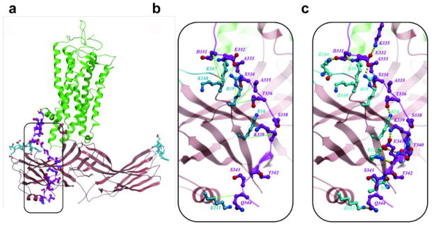
a, An overview of the computational model.
b, Predicted interactions of the rhodopsin C-terminus with arrestin, showing strong to medium pairwise restraints between Cβ atoms of rhodopsin and arrestin residues identified by disulfide crosslinking.
c, same as in b, but showing predicted hydrogen bonding and ionic interactions for the C-terminal residues of rhodopsin.
Extended Data Fig. 6. Dynamics of free 3A_arrestin and rhodopsin-bound arrestin determined by HDX.
a, HDX perturbation map between rhodopsin-bound arrestin and free arrestin, which is derived from the difference in the HDX rate between rhodopsin-bound arrestin and free arrestin. The bars below the arrestin sequence represent the peptide fragments resolved by mass spectrometry and the colors of the bars indicate the relative decrease in deuterium exchange (color code at bottom).
b, The thermal stability of free 3A_arrestin and the rhodopsin-arrestin complex shows that the rhodopsin-arrestin complex is more stable than free 3A_arrestin.
Extended Data Fig. 7. Cell based Tango assays to validate the rhodopsin-arrestin interface.
a, Cartoon illustration of the Tango assay for rhodopsin-arrestin interactions in cells.
b–c, Mutations of key arrestin (b) and rhodopsin (c) residues that mediate the rhodopsin-arrestin interactions. Tango assay were performed in the absence or presence of 10 μM all-trans-retinal (ATR). (n=3, error bars=SD).
Extended Data Fig. 8. Control experiments for disulfide bond cross-linking specificity.
a, The product of the cross-linking reaction of finger loop residue G77C with N3107.57C of TM7 was confirmed by western blots using anti-FLAG antibody (which detects arrestin-FLAG fusion) and anti-HA antibody (which detects rhodopsin-HA fusion). The cross-linked products are marked with arrow heads, and free-arrestin and free-rhodopsin are indicated by asterisks. Arrestin (3A) and rhodopsin (4M) without cysteine mutations do not form cross-linked products.
b, The cross-linked product of finger loop residue G77C with N3107.57C of TM7 was sensitive to treatment with reducing agents, indicating the cross-linking is mediated through disulfide bond formation.
c, A close-up view of arrestin finger loop residues M76C and G77C and their cross-linking with rhodopsin, which shows that G77C was specifically cross-linked to N3107.57C of TM7 and Q3128.49 of Helix 8, and M76C was cross-linked to N3107.57C of TM7 and Q3128.49C of Helix 8, but not to other residues.
d, Structure and cross-linking of finger loop N-terminal residues Q70C, E71C, and D72C of arrestin to T70C and K67C from ICL1 of rhodopsin.
e, Structure and cross-linking of arrestin back loop residues R319C and T320C to Q237ICL3C from TM5 of rhodopsin.
Extended Data Fig. 9. Structure comparison of the arrestin-bound rhodopsin with the β2-adrenergic receptor in complex with Gs protein (PDB code: 3SN6) and the inactive rhodopsin (PDB code: 1F88).
a, Superposition of arrestin-bound rhodopsin (green) with Gs protein-bound β2 adrenergic receptor (light yellow). The major conformational changes are indicated by arrows.
b, An intracellular view of a superposition of arrestin-bound rhodopsin (green) and Gs protein-bound β2-adrenergic receptor (light yellow).
c, Overlays of arrestin-bound rhodopsin (green) with inactive rhodopsin (pink) reveals specific conformational changes in each TM helix. The arrows indicate outward movements of TM helices.
d, RMSD of Cα atom differences between arrestin-bound rhodopsin and inactive rhodopsin shows the large conformational changes in TM5 and TM6.
Extended Data Fig. 10. Structure of rhodopsin-bound arrestin and its comparison with inactive and “pre-activated” arrestin.
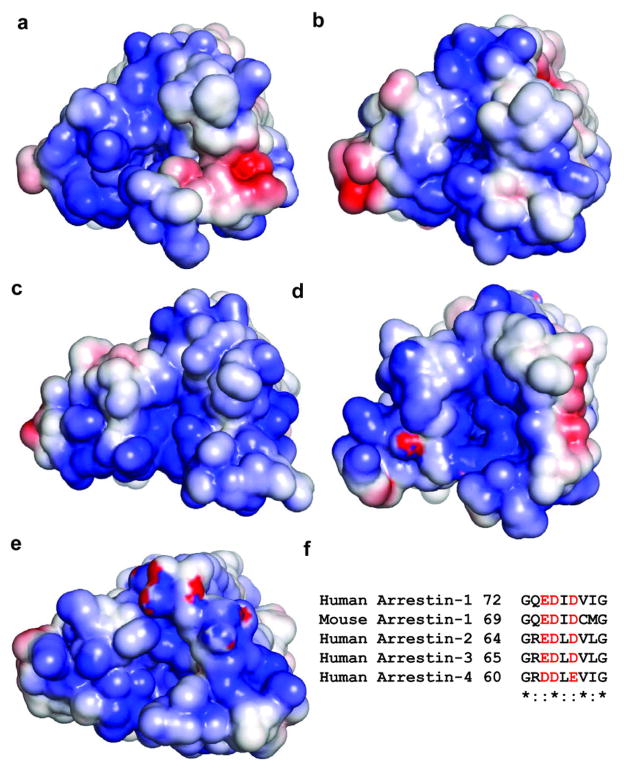
a–b, The charge potential surface map of rhodopsin from the rhodopsin-arrestin bound complex shows that the cytoplasmic rhodopsin TM bundle surface is positively charged (blue) whereas its C-terminal tail is negatively charged (red).
c–d, Charged surface of arrestin from the rhodopsin-arrestin bound complex shows that the arrestin finger loop is negatively charged (red) and its N-terminal β-strand interface is positively charged (blue). The charge distribution in rhodopsin and arrestin is complementary to each other for their interactions.
e, Comparison of rhodopsin-bound arrestin (light blue) with inactive arrestin (brown, PDB code: 1CF1), showing an ~20° rotation between the N- and C- domains of arrestin.
f, Comparison of rhodopsin-bound arrestin (dark brown) with pre-activated arrestin (light brown, PDB code: 4J2Q), showing conformational changes in the finger loop, which adopts an α-helical conformation (cyan) in the complex. The extended finger loop conformation would protrude into the rhodopsin TM bundle and is not compatible with receptor binding.
Computational model for the full rhodopsin-arrestin complex is shown in panels (b) and (d).
Extended Data Fig. 11. A computational model of phosphorylated rhodopsin in complex with arrestin and salt sensitivity of the rhodopsin-arrestin interaction.
a–d, An overall view (a) and close-up views (b–d) of the computational model of the rhodopsin C-tail with phospho-serine at positions 334, 338 and 343 in complex with arrestin.
e, The AlphaScreen control (biotin-His6) shows much less salt sensitivity than the interaction between His-tag-rhodopsin and biotin arrestin, which is very sensitive to salt, with an IC50 of around 200 mM NaCl (100 mM NaCl added to 100 mM salt of the original assay buffer) (n=3, error bars=SD).
Extended Data Fig. 12. A positive charge property is commonly found at the cytoplasmic side of GPCRs.
a–e, Surface charge potential of the cytoplasmic side of selected agonist bound GPCR structures: β1AR, PDB code: 2Y02 (a); β2AR, PDB code: 3PDS (b); A2A adenosine receptor, PDB code: 3QAK (c); serotonin receptor 5HT1B, PDB code: 4IAR (d); serotonin receptor 5HT2B, PDB code: 4IB4 (e). Positive and negative charge potentials are shown in blue and red, respectively.
f, Sequence alignment of the finger loop region highlighting negatively charged residues (shown in red), which are conserved in all subtypes of arrestins.
Extended Data Fig. 13. A possible role of the arrestin C-edge in lipid binding.
a,b The asymmetric assembly of the rhodopsin-arrestin complex in the presence of a lipid membrane bilayer, showing the C-edge of arrestin dipping into the lipid layer.
c,d, A close-up view of the C-edge of arrestin in the membrane layer, where the conserved hydrophobic side chains are shown. The figure was made using the computational model for the full rhodopsin-arrestin complex.
Acknowledgments
Portions of this research were carried out at the Linac Coherent Light Source (LCLS) at the SLAC National Accelerator Laboratory. LCLS is an Office of Science User Facility operated for the U.S. Department of Energy Office of Science by Stanford University. We thank staff members of the Life Science Collaborative Access Team (ID-21) of the Advanced Photon Source (APS) for assistance in data collection at the beam lines of sector 21, which is in part funded by the Michigan Economic Development Corporation and the Michigan Technology Tri-Corridor (Grant 085P1000817), and the General Medicine Collaborative Access Team for assistance in data collection at the beam lines of sector 23 (ID-23), funded in part with Federal funds from the National Cancer Institute (ACB-12002) and the National Institute of General Medical Sciences (AGM-12006). Use of APS was supported by the Office of Science of the US Department of Energy, under Contract No. DE-AC02-06CH11357. This work was supported in part by the Jay and Betty Van Andel Foundation, Ministry of Science and Technology (China) grants 2012ZX09301001 and 2012CB910403, 2013CB910600, XDB08020303, 2013ZX09507001, Amway (China), National Institute of Health grants, DK071662 (H.E.X.); GM073197 and GM103310 (C.S.P and B.C); GM102545 and GM104212 (K. M.); EY011500 and GM077561 (V.V.G.), the National Institutes of Health Common Fund in Structural Biology grants P50 GM073197 (V.C. and R.C.S.), P50 GM073210 (M.C.), and GM095583 (P.F.); National Institute of General Medical Sciences PSI: Biology grants U54 GM094618 (V.C., V.K., and R.C.S.), GM108635 (V.C.), U54 GM094599 (P.F.), GM097463 (J. S.), and U54 GM094586 (JCSG); NSF Science and Technology Center award 1231306 (J.C.H.S., P.F. and U.W); Swiss National Science Foundation grant 31003A_141235 (J.S); the Canada Excellence Research Chair program and the Anne & Max Tanenbaum Chair in Neuroscience at the University of Toronto (O.P.E.); and Science Foundation Ireland, grant 12/IA/1255 (M.C.). Parts of this work were also supported by the Helmholtz Gemeinschaft, the DFG Cluster of Excellence Center for Ultrafast Imaging, and the BMBF project FKZ 05K12CH1 (H.N.C., A.B., C.G., O.Y., T.W.); the Irene and Eric Simon Brain Research Foundation (R.L.). We thank Axel Brunger and Oliver Zeldin for analyzing the XFEL data and for advising on refinement; Bill Weis for advice on twin refinement and structure validation; James Rini for advice on the piggyBac expression system; Andrey Lebedev for his advice regarding the Zanuda program and the choice of the space group; and Angela Walker for final editing of the manuscript. We also thank the TianHe research and development team of National University of Defense Technology (NUDT) for computational resources.
Footnotes
Contributions: Y.K. initiated the project, developed the expression and purification methods for rhodopsin-arrestin complex, and bulk-purified expression constructs and proteins used in LCP crystallization for the SFX method; X.E.Z. collected the synchrotron data, helped with the SFX data collection, processed the data, and solved the structures; X.G. expressed and purified rhodopsin-arrestin complexes, characterized their binding and thermal stability, discovered the initial crystallization conditions with 9.7 MAG, prepared most crystals for synchrotron data collection, prepared all crystals for the final data collection by SFX, helped with SFX data collection, and established the initial cross-linking method for the rhodopsin-arrestin complex; Y.H. designed and performed Tango assays and disulfide bond cross-linking experiments; C.Z. developed the mammalian expression methods; P.W.dW helped with XFEL data processing and performed computational experiments; J.K., M.H.E.T., K. M. S-P., K. P., J. M., Y.J., X.Y.Z., and Q.C. performed cell culture, mutagenesis, protein purification, rhodopsin-arrestin binding experiments; W.L. and A.I. grew crystals and collected synchrotron data at APS and SFX data at LCLS, G.W.H. and Q.X. determined and validated the structure. Z.Z. and V.K. constructed the full model, the phosphorylated rhodopsin-arrestin model, and help writing the paper; D.W., S.L., D.J., C.K., Sh.B., and N.A. Z. helped with XFEL data collection and initial data analysis; S.B., M.M., and G.J.W. set up the XFEL experiment, performed the data collection, and commented on the paper. A.B., T.W., C.G., O.Y., and H.C. helped with XFEL data collection and data analysis, processed the data and helped with structure validation. G.M. W., B.P., and P.G. performed HDX experiments and helped with manuscript writing. J.L. helped initiate this collaborative project and with writing the paper. M.W. collected the 7.7 Å dataset at Swiss Light Source. A.M., C.S.P., and B.C. were responsible for EM images of rhodopsin-arrestin complexes. M.T. and Y.Z. performed mass spec experiments to validate the protein contents in the crystals; D. L. and M.C. provided the 9.7 MAG phase diagram and helped with SFX data collection and with writing the paper. J.S.T. provided a computational model of the rhodopsin-arrestin complex and helped with discussion and writing; K. D. and Y.D. helped with data analysis and twinning problems; R.J.L. constructed single-Cys arrestin-1 mutants for DEER and tested their binding to rhodopsin; S.A.V. expressed these mutants in E. coli and purified them; V.V.G. provided arrestin genes, designed single-Cys arrestin-1 mutants for DEER, and helped analyzing the data and writing the paper. Y.H. and H.J. performed computational modeling, figure preparation, and helped writing the paper; J.C.H.S. and U.W. designed the LCP injector and helped with data collection. Sh.B., S.R.-C., C.C., J. C., C.K., I.G. P. F., and R. F. helped with data collection, on site crystal characterization as well as data analysis, and validation of the structure. L.N.C. and O.P.E. prepared the rhodopsin mutant for DEER measurements. N.V.E. and W.L.H. performed DEER experiments and helped with manuscript writing. R.C.S. supervised crystal growth, data collection, structure solution and validation, and helped with manuscript writing. V.C. was the PI of the LCLS data collection, supervised crystal growth, data collection at APS and LCLS, structure solution and validation, and helped with manuscript writing; K. M. supervised research, analyzed data, and helped writing the paper. H.E.X. conceived the project, designed the research, performed synchrotron and LCLS data collection and structure solution, and wrote the paper with contributions from all authors.
The coordinates of the rhodopsin-arrestin complex and diffraction data have been deposited in the Protein Data Bank under accession number 4ZWJ.
References
- 1.Kim YJ, et al. Crystal structure of pre-activated arrestin p44. Nature. 2013;497:142–146. doi: 10.1038/nature12133. [DOI] [PubMed] [Google Scholar]
- 2.Shukla AK, et al. Structure of active beta-arrestin-1 bound to a G-protein-coupled receptor phosphopeptide. Nature. 2013;497:137–141. doi: 10.1038/nature12120. [DOI] [PMC free article] [PubMed] [Google Scholar]
- 3.Pitcher JA, Freedman NJ, Lefkowitz RJ. G protein-coupled receptor kinases. Annual review of biochemistry. 1998;67:653–692. doi: 10.1146/annurev.biochem.67.1.653. [DOI] [PubMed] [Google Scholar]
- 4.Wilden U, Hall SW, Kuhn H. Phosphodiesterase activation by photoexcited rhodopsin is quenched when rhodopsin is phosphorylated and binds the intrinsic 48-kDa protein of rod outer segments. Proceedings of the National Academy of Sciences of the United States of America. 1986;83:1174–1178. doi: 10.1073/pnas.83.5.1174. [DOI] [PMC free article] [PubMed] [Google Scholar]
- 5.Reiter E, Ahn S, Shukla AK, Lefkowitz RJ. Molecular mechanism of beta-arrestin-biased agonism at seven-transmembrane receptors. Annual review of pharmacology and toxicology. 2012;52:179–197. doi: 10.1146/annurev.pharmtox.010909.105800. [DOI] [PMC free article] [PubMed] [Google Scholar]
- 6.Kenakin TP. Biased signalling and allosteric machines: new vistas and challenges for drug discovery. British journal of pharmacology. 2012;165:1659–1669. doi: 10.1111/j.1476-5381.2011.01749.x. [DOI] [PMC free article] [PubMed] [Google Scholar]
- 7.Palczewski K, et al. Crystal structure of rhodopsin: A G protein-coupled receptor. Science. 2000;289:739–745. doi: 10.1126/science.289.5480.739. [DOI] [PubMed] [Google Scholar]
- 8.Rasmussen SG, et al. Crystal structure of the beta2 adrenergic receptor-Gs protein complex. Nature. 2011;477:549–555. doi: 10.1038/nature10361. [DOI] [PMC free article] [PubMed] [Google Scholar]
- 9.Cherezov V, et al. High-resolution crystal structure of an engineered human beta2-adrenergic G protein-coupled receptor. Science. 2007;318:1258–1265. doi: 10.1126/science.1150577. [DOI] [PMC free article] [PubMed] [Google Scholar]
- 10.Katritch V, Cherezov V, Stevens RC. Structure-function of the G protein-coupled receptor superfamily. Annual review of pharmacology and toxicology. 2013;53:531–556. doi: 10.1146/annurev-pharmtox-032112-135923. [DOI] [PMC free article] [PubMed] [Google Scholar]
- 11.Standfuss J, et al. The structural basis of agonist-induced activation in constitutively active rhodopsin. Nature. 2011;471:656–660. doi: 10.1038/nature09795. [DOI] [PMC free article] [PubMed] [Google Scholar]
- 12.Xu F, et al. Structure of an agonist-bound human A2A adenosine receptor. Science. 2011;332:322–327. doi: 10.1126/science.1202793. [DOI] [PMC free article] [PubMed] [Google Scholar]
- 13.Wang C, et al. Structural basis for molecular recognition at serotonin receptors. Science. 2013;340:610–614. doi: 10.1126/science.1232807. [DOI] [PMC free article] [PubMed] [Google Scholar]
- 14.Wacker D, et al. Structural features for functional selectivity at serotonin receptors. Science. 2013;340:615–619. doi: 10.1126/science.1232808. [DOI] [PMC free article] [PubMed] [Google Scholar]
- 15.Liu JJ, Horst R, Katritch V, Stevens RC, Wuthrich K. Biased signaling pathways in beta2-adrenergic receptor characterized by 19F-NMR. Science. 2012;335:1106–1110. doi: 10.1126/science.1215802. [DOI] [PMC free article] [PubMed] [Google Scholar]
- 16.Zhou XE, Melcher K, Xu HE. Structure and activation of rhodopsin. Acta Pharmacol Sin. 2012;33:291–299. doi: 10.1038/Aps.2011.171. [DOI] [PMC free article] [PubMed] [Google Scholar]
- 17.Gurevich VV, Hanson SM, Song XF, Vishnivetskiy SA, Gurevich EV. The functional cycle of visual arrestins in photoreceptor cells. Prog Retin Eye Res. 2011;30:405–430. doi: 10.1016/j.preteyeres.2011.07.002. [DOI] [PMC free article] [PubMed] [Google Scholar]
- 18.Smith SO. Insights into the activation mechanism of the visual receptor rhodopsin. Biochem Soc T. 2012;40:389–393. doi: 10.1042/BST20110751. [DOI] [PubMed] [Google Scholar]
- 19.Han M, Smith SO, Sakmar TP. Constitutive activation of opsin by mutation of methionine 257 on transmembrane helix 6. Biochemistry. 1998;37:8253–8261. doi: 10.1021/bi980147r. [DOI] [PubMed] [Google Scholar]
- 20.Ballesteros JA, Weinstein H. Integrated methods for the construction of three dimensional models and computational probing of structure-function relations in G-protein coupled receptors. Methods in Neurosciences. 1995;25:366–428. [Google Scholar]
- 21.Park JH, Scheerer P, Hofmann KP, Choe HW, Ernst OP. Crystal structure of the ligand-free G-protein-coupled receptor opsin. Nature. 2008;454:183–187. doi: 10.1038/nature07063. [DOI] [PubMed] [Google Scholar]
- 22.Scheerer P, et al. Crystal structure of opsin in its G-protein-interacting conformation. Nature. 2008;455:497–502. doi: 10.1038/nature07330. [DOI] [PubMed] [Google Scholar]
- 23.Choe HW, et al. Crystal structure of metarhodopsin II. Nature. 2011;471:651–655. doi: 10.1038/nature09789. [DOI] [PubMed] [Google Scholar]
- 24.Hirsch JA, Schubert C, Gurevich VV, Sigler PB. The 2.8 A crystal structure of visual arrestin: a model for arrestin’s regulation. Cell. 1999;97:257–269. doi: 10.1016/s0092-8674(00)80735-7. [DOI] [PubMed] [Google Scholar]
- 25.Granzin J, et al. X-ray crystal structure of arrestin from bovine rod outer segments. Nature. 1998;391:918–921. doi: 10.1038/36147. [DOI] [PubMed] [Google Scholar]
- 26.Shukla AK, et al. Visualization of arrestin recruitment by a G-protein-coupled receptor. Nature. 2014;512:218–222. doi: 10.1038/nature13430. [DOI] [PMC free article] [PubMed] [Google Scholar]
- 27.Standfuss J, Zaitseva E, Mahalingam M, Vogel R. Structural impact of the E113Q counterion mutation on the activation and deactivation pathways of the G protein-coupled receptor rhodopsin. Journal of molecular biology. 2008;380:145–157. doi: 10.1016/j.jmb.2008.04.055. [DOI] [PMC free article] [PubMed] [Google Scholar]
- 28.Xie G, Gross AK, Oprian DD. An opsin mutant with increased thermal stability. Biochemistry. 2003;42:1995–2001. doi: 10.1021/bi020611z. [DOI] [PubMed] [Google Scholar]
- 29.Standfuss J, et al. Crystal structure of a thermally stable rhodopsin mutant. Journal of molecular biology. 2007;372:1179–1188. doi: 10.1016/j.jmb.2007.03.007. [DOI] [PMC free article] [PubMed] [Google Scholar]
- 30.Martin EL, Rens-Domiano S, Schatz PJ, Hamm HE. Potent peptide analogues of a G protein receptor-binding region obtained with a combinatorial library. The Journal of biological chemistry. 1996;271:361–366. doi: 10.1074/jbc.271.1.361. [DOI] [PubMed] [Google Scholar]
- 31.Zhuang T, et al. Involvement of distinct arrestin-1 elements in binding to different functional forms of rhodopsin. Proceedings of the National Academy of Sciences of the United States of America. 2013;110:942–947. doi: 10.1073/pnas.1215176110. [DOI] [PMC free article] [PubMed] [Google Scholar]
- 32.Bayburt TH, et al. Monomeric rhodopsin is sufficient for normal rhodopsin kinase (GRK1) phosphorylation and arrestin-1 binding. The Journal of biological chemistry. 2011;286:1420–1428. doi: 10.1074/jbc.M110.151043. [DOI] [PMC free article] [PubMed] [Google Scholar]
- 33.Hanson SM, et al. Each rhodopsin molecule binds its own arrestin. Proceedings of the National Academy of Sciences of the United States of America. 2007;104:3125–3128. doi: 10.1073/pnas.0610886104. [DOI] [PMC free article] [PubMed] [Google Scholar]
- 34.Boutet S, et al. High-resolution protein structure determination by serial femtosecond crystallography. Science. 2012;337:362–364. doi: 10.1126/science.1217737. [DOI] [PMC free article] [PubMed] [Google Scholar]
- 35.Weierstall U, et al. Lipidic cubic phase injector facilitates membrane protein serial femtosecond crystallography. Nature communications. 2014;5:3309. doi: 10.1038/ncomms4309. [DOI] [PMC free article] [PubMed] [Google Scholar]
- 36.Liu W, et al. Serial femtosecond crystallography of G protein-coupled receptors. Science. 2013;342:1521–1524. doi: 10.1126/science.1244142. [DOI] [PMC free article] [PubMed] [Google Scholar]
- 37.Barty A, et al. software for high-throughput reduction and analysis of serial femtosecond X-ray diffraction data. J Appl Crystallogr. 2014;47:1118–1131. doi: 10.1107/S1600576714007626. [DOI] [PMC free article] [PubMed] [Google Scholar]
- 38.White TA, et al. CrystFEL: a software suite for snapshot serial crystallography. J Appl Crystallogr. 2012;45:335–341. doi: 10.1107/S0021889812002312. [DOI] [Google Scholar]
- 39.Deupi X, et al. Stabilized G protein binding site in the structure of constitutively active metarhodopsin-II. Proceedings of the National Academy of Sciences of the United States of America. 2012;109:119–124. doi: 10.1073/pnas.1114089108. [DOI] [PMC free article] [PubMed] [Google Scholar]
- 40.Altenbach C, Kusnetzow AK, Ernst OP, Hofmann KP, Hubbell WL. High-resolution distance mapping in rhodopsin reveals the pattern of helix movement due to activation. Proceedings of the National Academy of Sciences of the United States of America. 2008;105:7439–7444. doi: 10.1073/pnas.0802515105. [DOI] [PMC free article] [PubMed] [Google Scholar]
- 41.Kim M, et al. Conformation of receptor-bound visual arrestin. Proceedings of the National Academy of Sciences of the United States of America. 2012;109:18407–18412. doi: 10.1073/pnas.1216304109. [DOI] [PMC free article] [PubMed] [Google Scholar]
- 42.Kirchberg K, et al. Conformational dynamics of helix 8 in the GPCR rhodopsin controls arrestin activation in the desensitization process. Proceedings of the National Academy of Sciences of the United States of America. 2011;108:18690–18695. doi: 10.1073/pnas.1015461108. [DOI] [PMC free article] [PubMed] [Google Scholar]
- 43.Ostermaier MK, Peterhans C, Jaussi R, Deupi X, Standfuss J. Functional map of arrestin-1 at single amino acid resolution. Proceedings of the National Academy of Sciences of the United States of America. 2014;111:1825–1830. doi: 10.1073/pnas.1319402111. [DOI] [PMC free article] [PubMed] [Google Scholar]
- 44.Sommer ME, Hofmann KP, Heck M. Distinct loops in arrestin differentially regulate ligand binding within the GPCR opsin. Nature communications. 2012;3:995. doi: 10.1038/ncomms2000. [DOI] [PMC free article] [PubMed] [Google Scholar]
- 45.West GM, et al. Protein conformation ensembles monitored by HDX reveal a structural rationale for abscisic acid signaling protein affinities and activities. Structure. 2013;21:229–235. doi: 10.1016/j.str.2012.12.001. [DOI] [PMC free article] [PubMed] [Google Scholar]
- 46.Ohguro H, Palczewski K, Walsh KA, Johnson RS. Topographic Study of Arrestin Using Differential Chemical Modifications and Hydrogen-Deuterium Exchange. Protein Sci. 1994;3:2428–2434. doi: 10.1002/pro.5560031226. [DOI] [PMC free article] [PubMed] [Google Scholar]
- 47.Barnea G, et al. The genetic design of signaling cascades to record receptor activation. Proceedings of the National Academy of Sciences of the United States of America. 2008;105:64–69. doi: 10.1073/pnas.0710487105. [DOI] [PMC free article] [PubMed] [Google Scholar]
- 48.Gurevich VV, Benovic JL. Visual arrestin interaction with rhodopsin. Sequential multisite binding ensures strict selectivity toward light-activated phosphorylated rhodopsin. The Journal of biological chemistry. 1993;268:11628–11638. [PubMed] [Google Scholar]
- 49.Fotiadis D, et al. Atomic-force microscopy: Rhodopsin dimers in native disc membranes. Nature. 2003;421:127–128. doi: 10.1038/421127a. [DOI] [PubMed] [Google Scholar]
- 50.Zhang H, et al. Structure of the Angiotensin receptor revealed by serial femtosecond crystallography. Cell. 2015;161:833–844. doi: 10.1016/j.cell.2015.04.011. [DOI] [PMC free article] [PubMed] [Google Scholar]
- 51.Beckett D, Kovaleva E, Schatz PJ. A minimal peptide substrate in biotin holoenzyme synthetase-catalyzed biotinylation. Protein Sci. 1999;8:921–929. doi: 10.1110/ps.8.4.921. [DOI] [PMC free article] [PubMed] [Google Scholar]
- 52.Mossessova E, Lima CD. Ulp1-SUMO crystal structure and genetic analysis reveal conserved interactions and a regulatory element essential for cell growth in yeast. Mol Cell. 2000;5:865–876. doi: 10.1016/s1097-2765(00)80326-3. [DOI] [PubMed] [Google Scholar]
- 53.Alexandrov AI, Mileni M, Chien EYT, Hanson MA, Stevens RC. Microscale fluorescent thermal stability assay for membrane proteins. Structure. 2008;16:351–359. doi: 10.1016/j.str.2008.02.004. [DOI] [PubMed] [Google Scholar]
- 54.Caffrey M, Cherezov V. Crystallizing membrane proteins using lipidic mesophases. Nat Protoc. 2009;4:706–731. doi: 10.1038/nprot.2009.31. [DOI] [PMC free article] [PubMed] [Google Scholar]
- 55.Chen AH, Hummel B, Qiu H, Caffrey M. A simple mechanical mixer for small viscous lipid-containing samples. Chem Phys Lipids. 1998;95:11–21. doi: 10.1016/s0009-3084(98)00060-7. [DOI] [PubMed] [Google Scholar]
- 56.Xu F, Liu W, Hanson MA, Stevens RC, Cherezov V. Development of an Automated High Throughput LCP-FRAP Assay to Guide Membrane Protein Crystallization in Lipid Mesophases. Crystal growth & design. 2011;11:1193–1201. doi: 10.1021/cg101385e. [DOI] [PMC free article] [PubMed] [Google Scholar]
- 57.Liu W, Ishchenko A, Cherezov V. Preparation of microcrystals in lipidic cubic phase for serial femtosecond crystallography. Nat Protoc. 2014;9:2123–2134. doi: 10.1038/nprot.2014.141. [DOI] [PMC free article] [PubMed] [Google Scholar]
- 58.Kabsch W. Integration, scaling, space-group assignment and post-refinement. Acta crystallographica Section D, Biological crystallography. 2010;66:133–144. doi: 10.1107/S0907444909047374. [DOI] [PMC free article] [PubMed] [Google Scholar]
- 59.Boutet S, Williams GJ. The Coherent X-ray Imaging (CXI) instrument at the Linac Coherent Light Source (LCLS) New J Phys. 2010;12:035024. doi: 10.1088/1367-2630/12/3/035024. [DOI] [Google Scholar]
- 60.Siewert F, et al. Ultra-precise characterization of LCLS hard X-ray focusing mirrors by high resolution slope measuring deflectometry. Optics express. 2012;20:4525–4536. doi: 10.1364/OE.20.004525. [DOI] [PubMed] [Google Scholar]
- 61.White TA, et al. Crystallographic data processing for free-electron laser sources. Acta Crystallogr D. 2013;69:1231–1240. doi: 10.1107/S0907444913013620. [DOI] [PMC free article] [PubMed] [Google Scholar]
- 62.Battye TG, Kontogiannis L, Johnson O, Powell HR, Leslie AG. iMOSFLM: a new graphical interface for diffraction-image processing with MOSFLM. Acta crystallographica Section D, Biological crystallography. 2011;67:271–281. doi: 10.1107/S0907444910048675. [DOI] [PMC free article] [PubMed] [Google Scholar]
- 63.Duisenberg AJM. Indexing in Single-Crystal Diffractometry with an Obstinate List of Reflections. J Appl Crystallogr. 1992;25:92–96. doi: 10.1107/S0021889891010634. [DOI] [Google Scholar]
- 64.Kirian RA, et al. Structure-factor analysis of femtosecond microdiffraction patterns from protein nanocrystals. Acta crystallographica Section A, Foundations of crystallography. 2011;67:131–140. doi: 10.1107/S0108767310050981. [DOI] [PMC free article] [PubMed] [Google Scholar]
- 65.Karplus PA, Diederichs K. Linking crystallographic model and data quality. Science. 2012;336:1030–1033. doi: 10.1126/science.1218231. [DOI] [PMC free article] [PubMed] [Google Scholar]
- 66.Lebedev AA, Isupov MN. Space-group and origin ambiguity in macromolecular structures with pseudo-symmetry and its treatment with the program Zanuda. Acta crystallographica Section D, Biological crystallography. 2014;70:2430–2443. doi: 10.1107/S1399004714014795. [DOI] [PubMed] [Google Scholar]
- 67.Padilla JE, Yeates TO. A statistic for local intensity differences: robustness to anisotropy and pseudo-centering and utility for detecting twinning. Acta crystallographica Section D, Biological crystallography. 2003;59:1124–1130. doi: 10.1107/s0907444903007947. [DOI] [PubMed] [Google Scholar]
- 68.Mccoy AJ, et al. Phaser crystallographic software. J Appl Crystallogr. 2007;40:658–674. doi: 10.1107/S0021889807021206. [DOI] [PMC free article] [PubMed] [Google Scholar]
- 69.Emsley P, Lohkamp B, Scott WG, Cowtan K. Features and development of Coot. Acta crystallographica Section D, Biological crystallography. 2010;66:486–501. doi: 10.1107/S0907444910007493. [DOI] [PMC free article] [PubMed] [Google Scholar]
- 70.Murshudov GN, et al. REFMAC5 for the refinement of macromolecular crystal structures. Acta crystallographica Section D, Biological crystallography. 2011;67:355–367. doi: 10.1107/S0907444911001314. [DOI] [PMC free article] [PubMed] [Google Scholar]
- 71.Adams PD, et al. PHENIX: a comprehensive Python-based system for macromolecular structure solution. Acta crystallographica Section D, Biological crystallography. 2010;66:213–221. doi: 10.1107/S0907444909052925. [DOI] [PMC free article] [PubMed] [Google Scholar]
- 72.Chen VB, et al. MolProbity: all-atom structure validation for macromolecular crystallography. Acta crystallographica Section D, Biological crystallography. 2010;66:12–21. doi: 10.1107/S0907444909042073. [DOI] [PMC free article] [PubMed] [Google Scholar]
- 73.Tickle IJ. Statistical quality indicators for electron-density maps. Acta crystallographica Section D, Biological crystallography. 2012;68:454–467. doi: 10.1107/S0907444911035918. [DOI] [PMC free article] [PubMed] [Google Scholar]
- 74.DeLano WL, Lam JW. PyMOL: A communications tool for computational models. Abstr Pap Am Chem S. 2005;230:U1371–U1372. [Google Scholar]
- 75.Moeller A, Kirchdoerfer RN, Potter CS, Carragher B, Wilson IA. Organization of the Influenza Virus Replication Machinery. Science. 2012;338:1631–1634. doi: 10.1126/science.1227270. [DOI] [PMC free article] [PubMed] [Google Scholar]
- 76.Suloway C, et al. Automated molecular microscopy: The new Leginon system. J Struct Biol. 2005;151:41–60. doi: 10.1016/j.jsb.2005.03.010. [DOI] [PubMed] [Google Scholar]
- 77.Lander GC, et al. Appion: An integrated, database-driven pipeline to facilitate EM image processing. J Struct Biol. 2009;166:95–102. doi: 10.1016/j.jsb.2009.01.002. [DOI] [PMC free article] [PubMed] [Google Scholar]
- 78.Voss NR, Yoshioka CK, Radermacher M, Potter CS, Carragher B. DoG Picker and TiltPicker: Software tools to facilitate particle selection in single particle electron microscopy. J Struct Biol. 2009;166:205–213. doi: 10.1016/j.jsb.2009.01.004. [DOI] [PMC free article] [PubMed] [Google Scholar]
- 79.Scheres SHW, Nunez-Ramirez R, Sorzano COS, Carazo JM, Marabini R. Image processing for electron microscopy single-particle analysis using XMIPP. Nat Protoc. 2008;3:977–990. doi: 10.1038/nprot.2008.62. [DOI] [PMC free article] [PubMed] [Google Scholar]
- 80.Goswami D, et al. Time window expansion for HDX analysis of an intrinsically disordered protein. J Am Soc Mass Spectrom. 2013;24:1584–1592. doi: 10.1007/s13361-013-0669-y. [DOI] [PMC free article] [PubMed] [Google Scholar]
- 81.Pascal BD, et al. HDX Workbench: Software for the Analysis of H/D Exchange MS Data. J Am Soc Mass Spectr. 2012;23:1512–1521. doi: 10.1007/s13361-012-0419-6. [DOI] [PMC free article] [PubMed] [Google Scholar]
- 82.Klein-Seetharaman J, et al. Single-cysteine substitution mutants at amino acid positions 55–75, the sequence connecting the cytoplasmic ends of helices I and II in rhodopsin: reactivity of the sulfhydryl groups and their derivatives identifies a tertiary structure that changes upon light-activation. Biochemistry. 1999;38:7938–7944. doi: 10.1021/bi990013t. [DOI] [PubMed] [Google Scholar]
- 83.Li Z, Michael IP, Zhou D, Nagy A, Rini JM. Simple piggyBac transposon-based mammalian cell expression system for inducible protein production. Proceedings of the National Academy of Sciences of the United States of America. 2013;110:5004–5009. doi: 10.1073/pnas.1218620110. [DOI] [PMC free article] [PubMed] [Google Scholar]
- 84.Reeves PJ, Callewaert N, Contreras R, Khorana HG. Structure and function in rhodopsin: high-level expression of rhodopsin with restricted and homogeneous N-glycosylation by a tetracycline-inducible N-acetylglucosaminyltransferase I-negative HEK293S stable mammalian cell line. Proceedings of the National Academy of Sciences of the United States of America. 2002;99:13419–13424. doi: 10.1073/pnas.212519299. [DOI] [PMC free article] [PubMed] [Google Scholar]
- 85.Wang W, et al. Chromosomal transposition of PiggyBac in mouse embryonic stem cells. Proceedings of the National Academy of Sciences of the United States of America. 2008;105:9290–9295. doi: 10.1073/pnas.0801017105. [DOI] [PMC free article] [PubMed] [Google Scholar]
- 86.Bayburt TH, Leitz AJ, Xie G, Oprian DD, Sligar SG. Transducin activation by nanoscale lipid bilayers containing one and two rhodopsins. The Journal of biological chemistry. 2007;282:14875–14881. doi: 10.1074/jbc.M701433200. [DOI] [PubMed] [Google Scholar]
- 87.Hanson SM, et al. Differential interaction of spin-labeled arrestin with inactive and active phosphorhodopsin. Proceedings of the National Academy of Sciences of the United States of America. 2006;103:4900–4905. doi: 10.1073/pnas.0600733103. [DOI] [PMC free article] [PubMed] [Google Scholar]
- 88.Hanson SM, et al. Structure and function of the visual arrestin oligomer. The EMBO journal. 2007;26:1726–1736. doi: 10.1038/sj.emboj.7601614. [DOI] [PMC free article] [PubMed] [Google Scholar]
- 89.Fleissner MR, Cascio D, Hubbell WL. Structural origin of weakly ordered nitroxide motion in spin-labeled proteins. Protein Sci. 2009;18:893–908. doi: 10.1002/pro.96. [DOI] [PMC free article] [PubMed] [Google Scholar]
- 90.Lietzow MA, Hubbell WL. Motion of spin label side chains in cellular retinol-binding protein: correlation with structure and nearest-neighbor interactions in an antiparallel beta-sheet. Biochemistry. 2004;43:3137–3151. doi: 10.1021/bi0360962. [DOI] [PubMed] [Google Scholar]
- 91.Qiu H, Caffrey M. The phase diagram of the monoolein/water system: metastability and equilibrium aspects. Biomaterials. 2000;21:223–234. doi: 10.1016/s0142-9612(99)00126-x. [DOI] [PubMed] [Google Scholar]
- 92.Misquitta Y, et al. Rational design of lipid for membrane protein crystallization. J Struct Biol. 2004;148:169–175. doi: 10.1016/j.jsb.2004.06.008. [DOI] [PubMed] [Google Scholar]
- 93.Misquitta LV, et al. Membrane protein crystallization in lipidic mesophases with tailored bilayers. Structure. 2004;12:2113–2124. doi: 10.1016/j.str.2004.09.020. [DOI] [PubMed] [Google Scholar]
- 94.ICM Manual v. 3.8. MolSoft LLC; La Jolla, CA: 2014. [Google Scholar]
- 95.Coin I, et al. Genetically encoded chemical probes in cells reveal the binding path of urocortin-I to CRF class B GPCR. Cell. 2013;155:1258–1269. doi: 10.1016/j.cell.2013.11.008. [DOI] [PMC free article] [PubMed] [Google Scholar]
- 96.Arnautova YA, Abagyan RA, Totrov M. Development of a new physics-based internal coordinate mechanics force field and its application to protein loop modeling. Proteins. 2011;79:477–498. doi: 10.1002/prot.22896. [DOI] [PMC free article] [PubMed] [Google Scholar]


