Abstract
Acute coronary syndrome (ACS) is frequently associated with the sudden rupture of a vulnerable atherosclerotic plaque within the coronary artery. Several unique physiological features, including a thin fibrous cap accompanied by a necrotic lipid core, are the targeted indicators for identifying the vulnerable plaques. Intravascular ultrasound (IVUS), a catheter-based imaging technology, has been routinely performed in clinics for more than 20 years to describe the morphology of the coronary artery and guide percutaneous coronary interventions. However, conventional IVUS cannot facilitate the risk assessment of ACS because of its intrinsic limitations, such as insufficient resolution. Renovation of the IVUS technology is essentially needed to overcome the limitations and enhance the coronary artery characterization. In this paper, a multi-frequency intravascular ultrasound (IVUS) imaging system was developed by incorporating a higher frequency IVUS transducer (80 to 150 MHz) with the conventional IVUS (30–50 MHz) system. The newly developed system maintains the advantage of deeply penetrating imaging with the conventional IVUS, while offering an improved higher resolution image with IVUS at a higher frequency. The prototyped multi-frequency catheter has a clinically compatible size of 0.95 mm and a favorable capability of automated image co-registration. In vitro human coronary artery imaging has demonstrated the feasibility and superiority of the multi-frequency IVUS imaging system to deliver a more comprehensive visualization of the coronary artery. This ultrasonic-only intravascular imaging technique, based on a moderate refinement of the conventional IVUS system, is not only cost-effective from the perspective of manufacturing and clinical practice, but also holds the promise of future translation into clinical benefits.
I. Introduction
Vulnerable plaque has been hypothesized as an unstable atherosclerosis plaque building up on the walls of arteries, whose rupture is primarily responsible for acute coronary syndrome (AC S) and sudden cardiac death [1]. The thin-cap fibroatheroma (TCFA), which is the phenotype of vulnerable plaque, possesses the unique morphological features of a thin fibrous cap (<65 μm) and a large necrotic core underneath [2]. These morphological features at a tiny scale are frequently used as the indicators of TCFA, and can be used to facilitate the risk assessment of AC S. High-resolution intravascular imaging techniques, which can identify TCFA precisely, are essentially needed to provide a detailed anatomic structure of the coronary artery wall with the goal of evaluating the plaque vulnerability [3], [4].
The catheter-based grayscale intravascular ultrasound (IVUS) imaging, based on the echogenicity of acoustic waves, has been clinically available for 20 years to provide the cross-sectional visualization of the coronary artery wall and the quantitative evaluation of the lumen dimensions and the plaque area [5], [6]. The aperture size of the piezoelectric transducer incorporated at the catheter tip, usually smaller than 0.8 mm, is strictly limited by the confined size of the coronary artery lumen and the curvy structure of coronary artery system [7]. The typical center frequencies of IVUS transducers range from 20 to 40 MHz, providing 70 to 200 μm axial resolution, 200 to 400 μm lateral resolution, and 5 to 10 mm imaging depth [8], [9]. As a result, the spatial resolution of conventional IVUS is insufficient to measure the thin fibrous cap thickness, which is usually less than 65 μm. A newly developed RF backscatter spectrum analysis algorithm, Virtual Histology IVUS system (VH-IVUS), is capable of predicting the plaque vulnerability by characterizing plaque composition [10]–[12]. It is also a fact that data analyzed by VH is displayed on the order of 250 μm, which intrinsically downgrades the reliability of detecting the thin fibrous cap with this technique [13]. Super-harmonic IVUS imaging has been recently developed to image coronary vasa vasorum during contrast agent injection; however, in vivo validation and long-term optimization of this technique are needed to prove its capability to perform accurate vulnerable plaque assessment [14]. Optical coherence tomography (OCT), which utilizes back-scattered infrared light to generate high-speed and high-spatial-resolution (10 to 30 μm) images of microstructures of blood vessels such as the thin fibrous cap, is hypothesized to be a substitute for IVUS [15], [16]. However, the penetration depth through blood and vascular tissues of OCT is shallow. A synergistic approach combining IVUS and OCT seems favorable by simultaneously providing the deep penetration depth of IVUS and the high spatial resolution of OCT [17]. Several designs of integrated IVUS-OCT catheters have previously been evaluated both in vitro and in vivo to demonstrate the feasibility of this dual-modality intravascular imaging technique, which allows more accurate plaque characterization than using IVUS or OCT alone [17]–[20]. Nevertheless, technical requirements such as advancing IVUS-OCT catheter design, increasing the imaging speed, and enhancing the accuracy of the co-registration between IVUS and OCT images must be satisfied before this technique can be implemented in clinical practice [20]. In addition, the manufacturing cost of such a hybrid system will be dramatically increased because two independent systems must be integrated into one single unit, which requires deliberation between translational strategies and long-term clinical utility [21]. Given the fact that OCT is the optical analog of ultrasound, a question is then raised: can ultra-high frequency ultrasonic imaging be considered as an alternative and cost-effective solution to replace OCT? Ultra-high frequency IVUS at 80 MHz has been previously investigated and proved to be able to improve artery characterization with much higher axial resolution [22]. Even though there is a foreseeable drawback that higher frequency ultrasound will have stronger attenuation in the blood and vascular tissue, such transducers at 80 MHz center frequency can still provide an imaging depth of 2 mm, which is comparable to the penetration depth of OCT. In addition, further increasing the frequency and bandwidth of the ultrasound transducer is a possible approach to reach the axial resolution level of OCT.
Although it is hard to identify the vulnerable plaques with conventional IVUS because of its low resolution, it is still a reliable technique that cannot be easily substituted in the near future because of its accurate and deeply penetrating imaging capability [4]. Therefore, compared with integrated IVUS-OCT, incorporating another transducer at a higher frequency into the current IVUS system seems to be a simpler and more cost-effective approach to overcome the resolution limit of IVUS [4]. In this paper, we present the development of a multi-frequency IVUS system by integrating a conventional transducer (35 MHz) and an ultrahigh-frequency transducer (80 to 150 MHz) into a single catheter. Three prototypes of the multi-frequency IVUS catheters with different frequency combinations (35/90 MHz, 35/120 MHz, and 35/150 MHz) were fabricated and evaluated. The two transducer elements were arranged in a back-to-back configuration to facilitate automatic image co-registration at the same longitudinal location of the artery. The flexible catheters were miniaturized to have an outer diameter of 0.95 mm and a front rigid length of 2 mm to enable the catheters’ clinical compatibility. The multi-frequency IVUS imaging was assessed with a tissue-mimicking phantom with and without the presence of blood to evaluate the imaging depth, resolution, and contrast-to-noise ratio (CNR) of the imaging system. In vitro intravascular imaging of human cadaver coronary arteries with atherosclerosis was conducted to demonstrate the merit of multi-frequency IVUS which possesses the complementary nature of both low-frequency and high-frequency transducers. The system provides the deep penetration to image the whole artery wall of the low-frequency transducer and the fine resolution in the lumen area of the high-frequency transducer, allowing more comprehensive visualization of the coronary artery. These results suggest that the multi-frequency IVUS system appears to be a feasible and cost-effective approach to overcome the current limitations of conventional IVUS systems.
II. Method
A. Catheter Design and Fabrication
The square element size of transducer was restricted to be less than 0.8 mm in the conventional IVUS catheter. To fit the two transducers into the small catheter, the transducer element size and thickness were fixed to be 0.5 × 0.5 mm and 0.3 mm, respectively, for various center frequencies (35 MHz, 90 MHz, 120 MHz, and 150 MHz) in this study. Many different piezoelectric materials, including piezoceramics, piezoelectric polymers, and ferroelectric single crystals, can be used when designing a single- element transducer. Choices between the materials are made based on the piezoelectric properties and the specific requirements of the designed transducers such as center frequency, aperture size, and focal depth. Electromechanical coupling coefficient (kt), piezoelectric coefficient (d33) and dielectric permittivity ( ), listed in Table I, are the major parameters that determine the performance of a transducer [23]. Because the transducer aperture size is already determined in this study, the effects caused by dielectric permittivity should be carefully taken into account during the material selection because the dielectric permittivity, together with the surface area of piezoelectric material, determines the electrical impedance of a transducer [22]. An electrical impedance of 50 Ω properly matched to the electronics will result in an optimized sensitivity in both transmitting and receiving. Pb(Zr, Ti)O3 (PZT) ceramics have been widely used in fabrication of IVUS transducers in the frequency range of 20 to 50 MHz [24]. Compared with PZT, the recently developed single crystal Pb(Mg1/3Nb2/3)–PbTiO3 (PMN-PT) (from H. C. Materials Inc., Bolingbrook, IL) exhibits improved piezoelectric performance because of its outstanding kt and d33 (Table I), making it a more favorable candidate for ultrasonic transducer fabrication [25]. In addition, PMN-PT is more suitable for high sensitivity, small aperture ultrasound transducer application in a frequency range of 20 to 100 MHz, such as IVUS transducers, because of its superior dielectric permittivity value ( ), which causes the electrical impedance of the transducer to be better matched with the 50-Ω electronics within a tiny surface area. In consequence, PMN-PT was used in this study to fabricate the 35-MHz and 90-MHz transducer elements for the multi-frequency IVUS catheter. Nevertheless, for a center frequency over 100 MHz, the electrical impedance mismatch between the PMN-PT transducer and the acquisition platform will become significant for the same element size, and it is very challenging to further miniaturize the aperture size of the element to be less than 0.3 mm. A need for materials with even lower dielectric permittivity arises for fabricating transducers with center frequency of over 100 MHz. Lead-free single-crystal lithium niobate (LiNbO3 or LNO) provides a comparable kt to PZT, a much lower dielectric permittivity, and high longitudinal sound speed (v ~ 7340 m/s). It is suitable for designing sensitive large-aperture, high-frequency single-element transducers [26]. Therefore, LNO was selected to fabricate the 120-MHz and 150-MHz transducer elements.
TABLE I.
Piezoelectric Properties of Materials for IVUS Imaging Application.
The combination of two transducer elements in the multi-frequency IVUS catheter shares a similar principle with the integration of a transducer and optical probe in the IVUS-OCT catheter, as well as the hybrid catheter design for the other multi-modality intravascular imaging systems. The design scheme of the intravascular catheter should not only allow for the technical feasibility but also fulfill the clinical requirements. Several studies on the design of integrated IVUS-OCT catheters have been reported individually [17]–[20]. Each of the designs carries its own features and limitations. Based on the curvy structure of the cardiovascular system, a catheter with small outer diameter (OD), short front rigid length, and high flexibility is required to enable the safe delivery of catheter to the coronary artery [20]. Given the fact that the cardiovascular intervention procedure is time-limited, the multi-frequency IVUS system should be able to facilitate accurate fusion of two IVUS in a real-time manner. Based on the previous IVUS-OCT catheter designs, three design schemes for the multi-frequency IVUS catheter, with different configurations of how the two transducers of the same shape are aligned, are presented and summarized in Fig. 1. These design schemes include aligning the two transducers in the configurations of left-and-right, fore-and-aft, and back-to-back. For the left-and-right configuration [Fig. 1(a)], on-line image co-registration can be achieved by implementing a simple post-processing algorithm because the two transducers are imaging the same cross section within each image frame. However, this design scheme has an enlarged OD that is almost double that of the single-element IVUS catheter. The fore-and-aft configuration [Fig. 1(b)] has a satisfactory OD that is the same size as the single-element IVUS catheter, but the increased front rigid length makes it less flexible when going through sharp turns in the cardiovascular system. Moreover, image co-registration must be performed through pull-back scanning because the two transducers have a separation of more than 0.5 mm, which may result in inaccurate image co-registration for the artery walls, which will be changing dynamically during each cardiac cycle. As shown in Fig. 1(c), the back-to-back configuration provides a solution to the image co-registration problem in the fore-and-aft configuration because the two transducers generate images of the same cross section within one frame. This design scheme is preferred to the other two because it aligns the two transducers in the thickness direction, thus having the most effective use of space inside the cylindrical housing, and consequently offers a small OD and short front rigid length. Furthermore, based on the unique feature of back-to-back configuration, the real-time image co-registration at two frequencies can be accomplished by simply rotating one of the IVUS images of the same cross section by 180°.
Fig. 1.
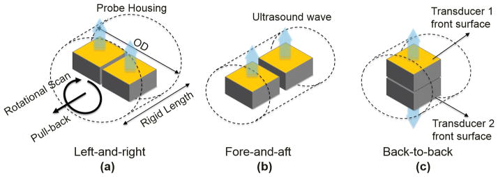
Illustrations of design schemes of multi-frequency IVUS catheter: (a) left-and-right configuration, (b) fore-and-aft configuration, and (c) back-to-back configuration.
In this study, three prototypes of back-to-back multi-frequency IVUS catheters with different frequency combinations (35/90 MHz, 35/120 MHz, and 35/150 MHz) were fabricated and evaluated. The general fabrication techniques described by Cannata et al. were used to prepare the single-element IVUS transducer before assembling them into a catheter [26]. The PMN-PT single crystals were lapped to 30 and 28 μm for the IVUS transducers operating at 35 and 90 MHz, respectively. LNO wafers of 22 and 15 μm were also acquired to fabricate the transducers at 120 and 150 MHz. All of the wafers were sputtered with a 1500-Å chrome/gold layer on both sides to serve as the front and back electrodes. Because of the difficulties of lapping the piezoelectric material down to a thickness less than 5 μm, only the 35- and 90-MHz transducers had a matching layer made of a mixture of Insulcast 501 (ITW Polymers Coatings North America, Montgomeryville, PA) and 2 to 3 μm silver particles. The matching layer was cast on to the front electrode of piezoelectric material, and then lapped to the designed thickness listed in Table II. Conductive epoxy (E-Solder 3022, Von Roll USA Inc., Schenectady, NY) was cast onto the back electrodes of the wafers, and all of the wafers were lapped to a thickness of 0.3 mm. The transducer element, together with the backing layer, was diced into a 0.5 × 0.5 mm square shape. The front electrode and back electrode were connected to the shielding wires and central wires of the coaxial cable insulated by the epoxy, respectively. A parylene layer (PDS2010, Specialty Coating Systems Inc., Indianapolis, IN) was deposited on to the entire element of the transducers to serve as the second matching layer of the 35- and 90-MHz transducers, and the first matching layer for the 120- and 150-MHz transducers. The thickness of the parylene layer for each transducer is listed in Table II. The two elements of different center frequencies were carefully aligned into the back-to-back configuration before being inserted into a two-window stainless steel cap (0.95 mm OD and 2 mm length). A polyimide layer was bonded by epoxy between the two backings of the IVUS transducers so as to further insulate the electrical signals. A triple-wrapped torque coil (OD: 0.9 mm) was connected to the catheter cap, covering the two electrical wires of the transducers to provide smooth torque translation. The two coaxial cables, a total of four electrical wires, were then connected to the separated channels of an eight-channel slip ring (SRH0317, Prosper M&E Tech Co., Hangzhou, China) to allow for the IVUS signal coupling for the two transducers during the rotational scan. The schematic and photograph of a back-to-back multi-frequency IVUS catheter were shown in Figs. 2(a) and 2(b). The overall size of the multi-frequency IVUS catheter is 0.95 mm in diameter with a front rigid length of 2 mm, which is comparable to the size of a commercial IVUS catheter.
TABLE II.
Properties of the Materials Used in IVUS Transducer Fabrication [26].
| Material | Use | Density (g/cm3) | Longitudinal sound speed (m/s) | Acoustic impedance (MRayl) |
|---|---|---|---|---|
| Insulcast 501 and 2–3μm silver particles | 1st Matching layer for | 3.86 | 1900 | 7.3 |
| 30 MHz (12 μm) | ||||
| 90 MHz (5 μm) | ||||
| Parylene | Second matching layer for | 1.18 | 2200 | 2.6 |
| 30 MHz (12 um) | ||||
| 90 MHz (5 μm); | ||||
| First matching layer for | ||||
| 120 MHz (3 μm) | ||||
| 150 MHz (2 μm) | ||||
| E-Solder 3022 | Backing layer | 3.20 | 1890 | 5.9 |
| EPO-TEK 301 | Insolating epoxy | 1.15 | 2650 | 3.1 |
Fig. 2.
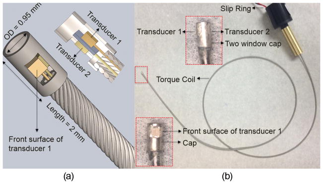
(a) Diagram of back-to-back multi-frequency IVUS catheter. Middle: 3-D diagram. Left-bottom: sectional diagram. (b) Photograph of a multi-frequency IVUS catheter prototype. Enlarged photograph: side view (top) and front view (bottom) of catheter tip.
B. Phantom Preparation and Experimental System Setup
An agar-based tissue-mimicking phantom with silicon carbide powder as the sound scatters (Fig. 3), having a 3-mm diameter lumen in the center, was fabricated to evaluate the CNR and the imaging depth of the multi-frequency IVUS catheter [28], [29]. A polyimide tube with a 1.5 mm OD and a 50 μm wall thickness was placed right next to the central lumen. A graphite rod with a 0.5 mm OD was placed at a distance of 0.5 mm away from the border of central lumen. The polyimide tube wall was designed to be a resolution target which was an analog to the thin fibrous cap. The graphite rod was a target with strong acoustic reflection.
Fig. 3.
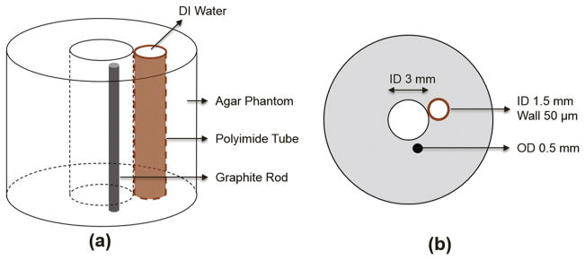
Illustration of agar-based tissue-mimicking phantom: (a) 3-D diagram and (b) sectional diagram.
The experimental imaging setup is illustrated in Fig. 4. A low-frequency pulser (AVTECH AVB2-TB-C, Avtech Electrosystems Ltd., Ogdensburg, NY) and a high-frequency pulser (AVTECH AVB2-TC-C, Avtech Electrosystems Ltd.) were used to excite the low-frequency transducer (35 MHz) and the high-frequency transducer (90, 120, and 150 MHz), respectively. The received RF signals were amplified by 33 dB (Miteq AU1114, Miteq Inc., Hauppauge, NY), and digitized by a 12-bit data acquisition board (Alazar Technologies Inc., Pointe-Claire, Canada) at a sampling frequency of 1.8 Gsample/s. Two function generators were used to synchronize the pulser/receiver, digitizer, and the motor unit, and one of them has a 50 μs time delay with respect to the other. The saved RF data were processed and displayed using a custom-developed LabVIEW program (National Instruments, Austin, TX). During the imaging experiments, the catheter tip was positioned inside the central lumen of the phantom and the catheter was rotated by the motor unit while the phantom and the slip ring were kept stationary.
Fig. 4.
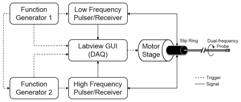
A diagram of the multi-frequency IVUS imaging system.
III. Results and Discussion
A. Transducer Characterization
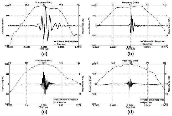
Pulse-echo testing [26] was performed to evaluate the performance of the transducers. An X-cut quartz target, placed at an approximate distance of 1.9 mm away from the transducers, was used as a reflecting target during the tests. The received echo signals in the time domain and the frequency responses of the 35-MHz transducers of the three catheters were recorded and only one of them, as a representative, is shown in Fig. 5(a). The echo signals and the frequency responses of the 90-, 120-, and 150-MHz transducers from the pulse-echo testing are displayed in Figs. 5(b)–5(d), respectively. To evaluate the axial and lateral resolution of the transducers, 6-μm-diameter tungsten wire targets were imaged. The measured center frequency, −6-dB fractional bandwidth, axial resolution, and lateral resolution of these transducers are listed in Table III.
Fig. 5.
Pulse-echo measurement results. Time-domain echo signals and frequency responses of (a) a representative 35-MHz transducer, (b) 90-MHz transducer, (c) 120-MHz transducer, and (d) 150-MHz transducer.
TABLE III.
Measured Center Frequencies, Bandwidths, and Resolutions of the Representative Transducers Used in This Study.
| Designed center frequency (MHz) | 35 | 90 | 120 | 150 |
| Measured center frequency (MHz) | 33.6 | 91.2 | 120.0 | 149.7 |
| −6-dB fractional bandwidth (%) | 47.7 | 42.0 | 24.1 | 28.1 |
| Axial resolution (μm) | 46.0 | 21.5 | 25.7 | 17.2 |
| Lateral resolution (μm) | 231.5 | 123.5 | 105.3 | 87.3 |
The measured center frequencies of these transducers are in reasonably good agreement with the designed center frequencies. The comparisons in Fig. 5 also show that as the center frequency of the transducer increases, the amplitude of the echo signals decreases. These transducers exhibit various bandwidth characteristics. The −6-dB fractional bandwidths of 35- and 90-MHz transducers are 47.4% and 42.0%, respectively, which is attributed to the better piezoelectric properties of the PMN-PT single-crystal as well as the presence of the silver epoxy matching layer. However, because of the missing of the matching layer, the 120- and 150-MHz transducers made from LNO exhibit narrower bandwidths of 24.1% and 28.1%, respectively. Theoretically, a broader bandwidth will result in a shorter pulse length during the monocycle excitation, and then a better axial resolution of a transducer can be achieved because of the broadband characteristics [30]. It should be noted that the axial resolution of the 90-MHz transducer is even better than that of the 120-MHz transducer. This can be explained by the narrowband characteristics of the 120-MHz transducer. These results suggest that the high-frequency transducers ranging from 90 to 150 MHz in this study are potentially capable of resolving the thin fibrous cap in the axial direction. The lateral resolution is primarily dependent on the beam width within the imaging range. Generally, the center frequency of a transducer has a dominant influence on the lateral resolution, and hence a higher frequency transducer is able to provide better lateral resolution. The measured lateral resolutions of different transducers are consistent with this theory; the 150-MHz transducer provides the best lateral resolution of 87.3 μm. The axial resolution (17.2 μm) of the 150-MHz transducer can reach the same level as OCT. However, given that the lateral resolution of the IVUS transducers in this study is approximately four times the axial resolution, the lateral resolution of IVUS is the least competitive aspect when comparing them to OCT.
B. Tissue-Mimicking Phantom Imaging
To evaluate the imaging capability of the multi-frequency IVUS catheter, tissue mimicking phantom images without the presence of blood were initially acquired. The central lumen and the polyimide tube were filled with deionized water. A phantom image [Fig. 6(a)] captured by one of the three 35-MHz IVUS demonstrated an imaging depth of 5 mm at this frequency. The graphite rod was clearly distinguished from the surrounding agar with a strong echo signal followed by an acoustic shadow. The front and back surfaces of the polyimide tube could be identified, but the actual thickness of the polyimide tube could not be precisely resolved because of insufficient resolution. Another important evaluation parameter of an IVUS image is the CNR, which is also critical for the detection of sub-resolution targets. The CNR was calculated as [23], [31]
Fig. 6.

Tissue-mimicking phantom images without presence of blood at (a) 35 MHz, (b) 90 MHz, (c) 120 MHz, and (d) 150 MHz. Dynamic range: 45 dB. Scale bar: 1 mm.
where meant and meann stand for the mean of the signal of the imaging target and the mean of the background noise; vart and varn represent the signal variance of the imaging target and the background noise. In this case, the imaging target is the agar and the background noise is the water-filled lumen within the polyimide tube. The CNR of the phantom image of the 35-MHz transducer is 5.1. The phantom images of the 90- and 120-MHz transducers are shown in Figs. 6(b) and 6(c), respectively. Because resolution has been improved, the front and back surfaces of the polyimide tube could be better differentiated. A more detailed structure around the boundary of the graphite rod could be visualized. Moreover, because of the stronger attenuation of higher frequency ultrasound, a significant decrease in imaging depths, about 2 mm and 1 mm compared with 5 mm for the 35-MHz transducer, was observed at 90 and 120 MHz, respectively. At the same time, the CNRs of the images at 90 and 120 MHz decreased to 2.1 and 1.6, respectively. Fig. 6(d) shows the phantom image generated by the 150-MHz transducer. Although the resolution of the image was further improved, the image could only penetrate to less than 500 μm in depth and provided weaker contrast for the strong acoustic reflectors, such as surface of polyimide tube and boundary of graphite rod. Thus, it appears that transducer at such frequency is not suitable for IVUS imaging applications.
Despite the decreased penetration depth and CNR, IVUS transducers of 90 and 120 MHz are still capable of providing valuable high-resolution information around the inner lumen area. The fused phantom images captured by the 35/90-MHz and 35/120-MHz catheters are shown in Figs. 7(a) and 7(b), respectively. The image co-registration in each imaging pair is accomplished by simply rotating one of the IVUS images by 180°. These results suggest that the multi-frequency catheters can achieve better characterization of the artery tissue by integrating the deep imaging depth of lower frequency transducer and the high resolution of the higher frequency transducer.
Fig. 7.
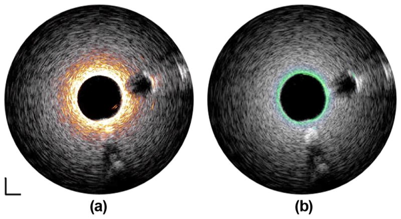
Fused tissue-mimicking phantom images captured by (a) 35/90-MHz multi-frequency IVUS catheter and (b) 35/120-MHz multi-frequency IVUS catheter. White: 35-MHz ultrasound image. Orange: 90-MHz ultrasound image. Green: 120-MHz ultrasound image. Dynamic range: 45 dB. Scale bar: 1 mm.
To further investigate the feasibility of the multi-frequency catheters in a setup that is closer to clinical settings, tissue-mimicking phantom imaging was performed with the presence of blood. The center lumen of the phantom was filled with fresh swine blood and the polyimide tube was still filled with deionized water. As expected, a slightly decreased penetration depth of 4 mm and a reduced CNR value of 3.2 were obtained in the image at 35 MHz [Fig. 8(a)] because of the strong attenuation of the blood in the lumen. As shown in Figs. 8(b)–8(d), the much stronger attenuation of the higher frequency ultrasonic waves in the blood dramatically limits the imaging depth and degrades the image quality. These results indicate that to improve imaging depth with a high-frequency transducer may require the temporary removal of luminal blood during the in vivo imaging, similar to the flushing mechanism in OCT, which is an intrinsic drawback of multi-frequency IVUS imaging.
Fig. 8.

Tissue-mimicking phantom images in presence of blood at (a) 35 MHz, (b) 90 MHz, (c) 120 MHz, and (d) 150 MHz. Dynamic range: 45 dB. Scale bar: 1 mm.
C. In Vitro Intravascular Imaging
Human cadaver coronary artery images acquired at 35, 90, and 120 MHz are displayed in Fig. 9. The 35-MHz transducer provides more complete morphological information of the coronary artery because of the deep penetration depth [Fig. 9(a)]. With the 90-MHz transducer, the three-layered structure (intima, media, and adventitia) indicated by the red arrow is identified in Fig. 9(b) because of the improved axial resolution. However, it is blurred and not apparent in Fig. 9(b). In Fig. 9(c), although the 120-MHz transducer can only image through the intima layer because of the limited penetration depth, an improvement in both axial resolution and lateral resolution is achieved, indicated by a reduced speckle size in the image of the intima layer. The fused image pairs acquired by the 35/90-MHz and 35/120-MHz integrated catheters are shown in Figs. 10(a) and 10(b), respectively. The integrated image pairs, combining the advantages of the high-resolution superficial image of lumen area offered by the high-frequency IVUS transducer (90 or 120 MHz) and the deep penetration image of the entire artery wall provided by the low-frequency transducer (35 MHz), yield a more comprehensive visualization of the artery wall and plaque volume.
Fig. 9.
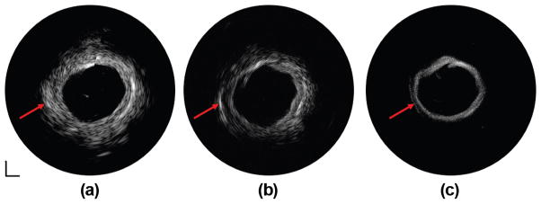
IVUS images of human coronary artery at (a) 35 MHz, (b) 90 MHz, and (c) 120 MHz. Dynamic range: 50 dB. Scale bar: 1 mm.
Fig. 10.
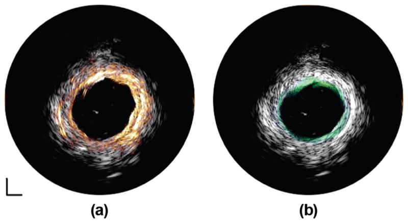
Fused IVUS images of human coronary artery captured by (a) 35/90-MHz multi-frequency IVUS catheter and (b) 35/120-MHz multi-frequency IVUS catheter. White: 35-MHz IVUS image. Orange: 90-MHz IVUS image. Green: 120-MHz IVUS image. Dynamic range: 50 dB. Scale bar: 1 mm.
The performance of the IVUS transducers used in this study are summarized in Fig. 11, including center frequency, imaging depth, imaging contrast, and imaging resolution. The results are in agreement with the classic ultrasound theory that increasing the center frequency of the transducer results in better imaging resolution and decreased imaging depth. Even though different piezoelectric materials were selected to fabricate the IVUS transducers at different center frequencies, there was still some electrical impedance mismatch between the IVUS transducers and electrical system because the transducer aperture size was fixed at 0.5 mm. Future implementation of a matching circuit into the system will potentially solve this issue and improve the overall performance of the multi-frequency IVUS catheter. The lateral resolution of the multi-frequency IVUS catheter system is almost three to four times worse than the axial resolution, which is also the technical barrier and natural shortcoming of all other IVUS systems. There is a significant gap between the conventional IVUS and the competitive technology OCT, indicated by the red dot, regarding the image resolution and penetration depth. Combining a higher frequency IVUS transducer in the frequency range of 90 to 120 MHz with the conventional IVUS catheter is a more feasible and simpler solution to reduce the limitation caused by insufficient resolution and fill the gap between the conventional IVUS and OCT. However, the requirement of temporary removal of luminal blood, with the goal of eliminating the stronger attenuation effect for higher frequency ultrasound, is a weakness of this technology that must be addressed in the future. Although further increasing the center frequency of the transducer to 150 MHz or higher could theoretically reach the resolution level of OCT, the extremely shallow imaging depth and reduced imaging contrast will dramatically degrade the image quality. Thus, it may not be worthwhile to use a transducer with such high frequencies for IVUS applications. As discussed previously, because of its broadband characteristics, the 90-MHz transducer exhibits a better axial resolution than the 120-MHz transducer. This suggests that the integration of a broader bandwidth transducer is favorable to further renovate the multi-frequency IVUS catheters. The newly developed micro-machined PIN-PMN-PT single-crystal 1–3 composite transducer at 40 MHz for IVUS application, providing an improved axial resolution of 43 μm and a comparable penetration depth to conventional IVUS transducers, was investigated [17], [32]. For the possible implementation of 1–3 composite material in multi-frequency IVUS imaging, the proposed 1–3 composite transducers in a frequency range of 60 to 90 MHz, indicated by the blue dashed dot in Fig. 11, serves as a more promising substitute for the high-frequency transducers in the multi-frequency IVUS catheters so that the enhanced resolution can be achieved without excessively sacrificing imaging depth. Furthermore, the mechanical flexibility of 1–3 composite material makes it possible to mechanically focus such a tiny transducer with the intention of further improving the lateral resolution in the near future.
Fig. 11.
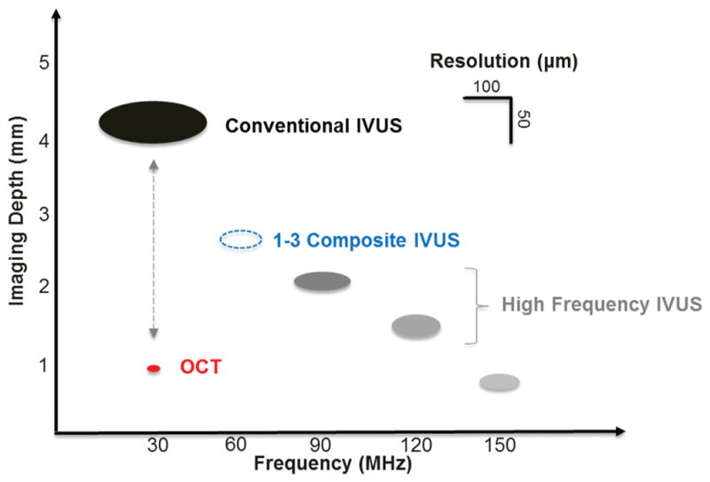
Summaries of IVUS transducers’ performances at different center frequencies in this study, including imaging depth, imaging contrast, and imaging resolution. Red dot: OCT. Dashed blue dot: 1–3 composite IVUS transducer.
IV. Conclusion
We have successfully developed and prototyped multi-frequency IVUS imaging system catheters with three different frequency combinations prepared using PMN-PT and LNO single crystals. The multi-frequency IVUS catheter, with a clinically compatible size of 0.95 mm in diameter, features the back-to-back arrangement of a conventional IVUS transducer and a high-frequency IVUS transducer to achieve accurate co-registration of two IVUS images. The performance of the high-frequency IVUS transducer at different frequency ranges (90, 120, and 150 MHz) was evaluated and compared with find the optimal frequency range for the high-frequency transducer in the multi-frequency IVUS catheter, considering imaging depth, imaging resolution, and CNR. Tissue-mimicking phantom imaging with and without the presence of blood shows that the multi-frequency catheter carries the complementary strengths of the deep imaging depth of the conventional IVUS and the high resolution of the high-frequency transducer. On the other hand, these results also point out a potential weakness of the multi-frequency catheter, which is that flushing of the luminal blood is required to ensure the functionality of this technique. The in vitro human cadaver coronary artery imaging demonstrates the capability of the multi-frequency catheter to provide more comprehensive visualization of the vascular structure and to facilitate the assessment of the vulnerable plaque. Compared with other multi-modality intravascular imaging techniques, the multi-frequency IVUS imaging capitalizes the advantage of cost-effectiveness because only a moderate modification of the current commercial IVUS system is needed. Additionally, the apparent clinical utility of this ultrasonic only technology can be promptly explored during the translational stage because most of the interventional physicians are familiar with the ultrasound technology. The future translation of the multi-frequency IVUS imaging into clinical use will not only consolidate the leading status of the IVUS technology in the interventional cardiology practice, but also lead to patient benefits.
Acknowledgments
This work is supported by the National Institute of Health under grants P41-EB002182 and R01-EB10090.
The authors acknowledge Dr. Z. Chen and Ms. J. Li for providing tissue samples. The authors also thank the individuals who donate their bodies and tissues for the advancement of education and research.
Biographies
 Teng Ma received his B.S.E. degree in 2011 from the University of Michigan, Ann Arbor, MI, majoring in biomedical engineering. He received his M.S. degree in biomedical engineering from the University of Southern California, Los Angeles, CA, in 2013. He joined the NIH Resource Center for Medical Ultrasonic Transducer Technology as a Research Assistant and Ph.D. candidate under the supervision of Dr. K. Kirk Shung and Dr. Qifa Zhou. In 2013, two of his papers were selected as Best Student Paper Finalists and were featured at the 2013 Joint UFFC, EFTF, and PFM Symposium. His research interests include medical ultrasound technology and multi-modality intravascular imaging by combining ultrasonic and optical techniques, such as intravascular ultrasound (IVUS), intravascular optical coherence tomography (IV-OCT), intravascular photoacoustic imaging (IVPA), and acoustic radiation force optical coherence elastography (ARF-OCE). He is also actively working in translational research and medical device commercialization with entrepreneurial spirit to translate innovative technology from research to clinical benefits.
 Mingyue Yu was born in Hebei Province, China. She received a B.E. degree from Tianjin University, China, in 2009. She started her Ph.D. study at the University of Southern California (USC), Los Angeles, CA, in 2013 under the support of the USC Provost’s Fellowship. Under the instruction of Dr. Qifa Zhou and Dr. K. Kirk Shung, Mingyue is conducting her research in the NIH Ultrasonic Transducer Resource Center (UTRC) on high-frequency ultrasonic transducer technology and intravascular ultrasonic imaging.
 Zeyu Chen received a B.E. degree from Central South University, China, in 2012. He is currently a Ph.D. candidate in the Department of Biomedical Engineering at the University of Southern California (USC). Under the direction of Dr. Qifa Zhou and Dr. K. Kirk Shung, he is conducting his research in the NIH Ultrasonic Transducer Resource Center (UTRC) on ultrasonic transducer fabrication.
 Chunlong Fei received his B.S. degree in physics from Wuhan University, China, in 2010. Currently, he is a joint Ph.D. student of the Department of Biomedical Engineering at University of Southern California, Los Angeles, CA, and the School of Physics and Technology at Wuhan University, China. His current research interests include the development of ferroelectric thin/thick films, and fabrication of high-frequency ultrasonic transducers for medical imaging applications.
 K. Kirk Shung obtained a B.S. degree in electrical engineering from Cheng-Kung University in Taiwan in 1968; an M.S. degree in electrical engineering from the University of Missouri, Columbia, MO, in 1970; and a Ph.D. degree in electrical engineering from the University of Washington, Seattle, WA, in 1975. He taught at The Pennsylvania State University, University Park, PA, for 23 years before moving to the Department of Biomedical Engineering, University of Southern California, Los Angeles, CA, as a professor in 2002. He is the Dean’s professor at University of Southern California. He has been the director of the NIH Resource on Medical Ultrasonic Transducer Technology since 1997. Dr. Shung is a life fellow of IEEE and a fellow of the Acoustical Society of America and the American Institute of Ultrasound in Medicine. He is a founding fellow of the American Institute of Medical and Biological Engineering. He received the IEEE Engineering in Medicine and Biology Society Early Career Award in 1985 and was the coauthor of a paper that received the best paper award for the IEEE Transactions on Ultrasonics, Ferroelectrics, and Frequency Control (UFFC) in 2000. He was elected an outstanding alumnus of Cheng-Kung University in Taiwan in 2001. He was selected as the distinguished lecturer for the IEEE UFFC society for 2002–2003. He received the Holmes Pioneer Award in Basic Science from the American Institute of Ultrasound in Medicine in 2010. He was selected to receive the academic career achievement award from the IEEE Engineering in Medicine and Biology Society in 2011. Dr. Shung has published more than 400 papers and book chapters. He is the author of the textbook Principles of Medical Imaging, published by Academic Press in 1992, and the textbook Diagnostic Ultrasound: Imaging and Blood Flow Measurements, published by CRC Press in 2005. He co-edited the book Ultrasonic Scattering by Biological Tissues, published by CRC Press in 1993. He is an associate editor of the IEEE Transactions on Ultrasonics, Ferroelectrics, and Frequency Control and a member of the editorial board of Ultrasound in Medicine and Biology. D r. Shung’s research interests are in ultrasonic transducers, high-frequency ultrasonic imaging, ultrasound microbeams, and ultrasonic scattering in tissues.
 Qifa Zhou received his Ph. D. degree from the Department of Electronic Materials and Engineering of Xi’an Jiaotong University, China, in 1993. He is currently a Research Professor at the NIH Resource on Medical Ultrasonic Transducer Technology and the Department of Biomedical Engineering and Industry & System Engineering at the University of Southern California (USC), Los Angeles, CA. Before joining USC in 2002, he worked in the Department of Physics at Zhongshan University in China; the Department of Applied Physics, Hong Kong Polytechnic University; and the Materials Research Laboratory, The Pennsylvania State University. Dr. Zhou is a fellow of International Society for Optics and Photonics (SPIE) and the American Institute for Medical and Biological Engineering (AIMBE). He is also a senior member of the IEEE Ultrasonics, Ferroelectrics, and Frequency Control (UFFC) Society and a member of the UFFC Society’s Ferroelectric Committee. He is a member of the Technical Program Committee of the IEEE International Ultrasonics Symposium. He is an Associate Editor of the IEEE Transactions on Ultrasonics, Ferroelectrics, and Frequency Control. His current research interests include the development of ferroelectric thin films, MEMS technology, nano-composites, and modeling and fabrication of high-frequency ultrasound transducers and arrays for medical imaging applications, such as photoacoustic imaging and intravascular imaging. He has published more than 130 journal papers in this area.
Contributor Information
Teng Ma, Department of Biomedical Engineering and the National Institutes of Health (NIH) Resource Center for Medical Ultrasonic Transducer Technology, University of Southern California, Los Angeles, CA.
Mingyue Yu, Department of Biomedical Engineering and the National Institutes of Health (NIH) Resource Center for Medical Ultrasonic Transducer Technology, University of Southern California, Los Angeles, CA.
Zeyu Chen, Department of Biomedical Engineering and the National Institutes of Health (NIH) Resource Center for Medical Ultrasonic Transducer Technology, University of Southern California, Los Angeles, CA.
Chunlong Fei, School of Physics and Technology, Wuhan University, Wuhan, Hubei, China.
K. Kirk Shung, Department of Biomedical Engineering and the National Institutes of Health (NIH) Resource Center for Medical Ultrasonic Transducer Technology, University of Southern California, Los Angeles, CA.
Qifa Zhou, Email: qifazhou@usc.edu, Department of Biomedical Engineering and the National Institutes of Health (NIH) Resource Center for Medical Ultrasonic Transducer Technology, University of Southern California, Los Angeles, CA.
References
- 1.Virmani R, Kolodgie FD, Burke AP, Farb A, Schwartz SM. Lessons from sudden coronary death: A comprehensive morphological classification scheme for atherosclerotic lesions. Arterioscler Thromb Vasc Biol. 2000 May;20:1262–1275. doi: 10.1161/01.atv.20.5.1262. [DOI] [PubMed] [Google Scholar]
- 2.Kolodgie FD, Burke AP, Farb A, Gold HK, Yuan J, Narula J, Finn AV, Virmani R. The thin-cap fibroatheroma: A type of vulnerable plaque: The major precursor lesion to acute coronary syndromes. Curr Opin Cardiol. 2001 Sep;16:285–292. doi: 10.1097/00001573-200109000-00006. [DOI] [PubMed] [Google Scholar]
- 3.Garcia-Garcia HM, Gonzalo N, Granada JF, Regar E, Serruys PW. Diagnosis and treatment of coronary vulnerable plaques. Expert Rev Cardiovasc Ther. 2008 Feb;6:209–222. doi: 10.1586/14779072.6.2.209. [DOI] [PubMed] [Google Scholar]
- 4.Puri R, Worthley MI, Nicholls SJ. Intravascular imaging of vulnerable coronary plaque: Current and future concepts. Nat Rev Cardiol. 2011 Mar;8:131–139. doi: 10.1038/nrcardio.2010.210. [DOI] [PubMed] [Google Scholar]
- 5.Potkin BN, Bartorelli AL, Gessert JM, Neville RF, Almagor Y, Roberts WC, Leon MB. Coronary artery imaging with intravascular high-frequency ultrasound. Circulation. 1990 May;81:1575–1585. doi: 10.1161/01.cir.81.5.1575. [DOI] [PubMed] [Google Scholar]
- 6.Aoki J, Abizaid AC, Serruys PW, Ong AT, Boersma E, Sousa JE, Bruining N. Evaluation of four-year coronary artery response after sirolimus-eluting stent implantation using serial quantitative intravascular ultrasound and computer-assisted grayscale value analysis for plaque composition in event-free patients. J Am Coll Cardiol. 2005 Nov 1;46:1670–1676. doi: 10.1016/j.jacc.2005.06.076. [DOI] [PubMed] [Google Scholar]
- 7.Foster FS, Pavlin CJ, Harasiewicz KA, Christopher DA, Turnbull DH. Advances in ultrasound biomicroscopy. Ultrasound Med Biol. 2000 Jan;26:1–27. doi: 10.1016/s0301-5629(99)00096-4. [DOI] [PubMed] [Google Scholar]
- 8.Elliott MR, Thrush AJ. Measurement of resolution in intravascular ultrasound images. Physiol Meas. 1996 Nov;17:259–265. doi: 10.1088/0967-3334/17/4/003. [DOI] [PubMed] [Google Scholar]
- 9.Brezinski ME, Tearney GJ, Weissman NJ, Boppart SA, Bouma BE, Hee MR, Weyman AE, Swanson EA, Southern JF, Fujimoto JG. Assessing atherosclerotic plaque morphology: Comparison of optical coherence tomography and high frequency intravascular ultrasound. Heart. 1997 May;77:397–403. doi: 10.1136/hrt.77.5.397. [DOI] [PMC free article] [PubMed] [Google Scholar]
- 10.Nair A, Kuban BD, Tuzcu EM, Schoenhagen P, Nissen SE, Vince DG. Coronary plaque classification with intravascular ultrasound radiofrequency data analysis. Circulation. 2002 Oct 22;106:2200–2206. doi: 10.1161/01.cir.0000035654.18341.5e. [DOI] [PubMed] [Google Scholar]
- 11.Nasu K, Tsuchikane E, Katoh O, Vince DG, Virmani R, Surmely JF, Murata A, Takeda Y, Ito T, Ehara M, Matsubara T, Terashima M, Suzuki T. Accuracy of in vivo coronary plaque morphology assessment: A validation study of in vivo virtual histology compared with in vitro histopathology. J Am Coll Cardiol. 2006 Jun 20;47:2405–2412. doi: 10.1016/j.jacc.2006.02.044. [DOI] [PubMed] [Google Scholar]
- 12.Nair A, Margolis MP, Kuban BD, Vince DG. Automated coronary plaque characterisation with intravascular ultrasound backscatter: Ex vivo validation. EuroIntervention. 2007 May;3:113–120. [PubMed] [Google Scholar]
- 13.Garcia-Garcia HM, Mintz GS, Lerman A, Vince DG, Margolis MP, van Es GA, Morel MA, Nair A, Virmani R, Burke AP, Stone GW, Serruys PW. Tissue characterisation using intravascular radiofrequency data analysis: Recommendations for acquisition, analysis, interpretation and reporting. EuroIntervention. 2009 Jun;5:177–189. doi: 10.4244/eijv5i2a29. [DOI] [PubMed] [Google Scholar]
- 14.Ma J, Martin K, Dayton PA, Jiang X. A preliminary engineering design of intravascular dual-frequency transducers for contrast-enhanced acoustic angiography and molecular imaging. IEEE Trans Ultrason Ferroelectr Freq Control. 2014 May;61:870–880. doi: 10.1109/TUFFC.2014.6805699. [DOI] [PMC free article] [PubMed] [Google Scholar]
- 15.Brezinski ME, Tearney GJ, Bouma BE, Boppart SA, Hee MR, Swanson EA, Southern JF, Fujimoto JG. Imaging of coronary artery microstructure (in vitro) with optical coherence tomography. Am J Cardiol. 1996 Jan 1;77:92–93. doi: 10.1016/s0002-9149(97)89143-6. [DOI] [PubMed] [Google Scholar]
- 16.Regar E, Schaar JA, Mont E, Virmani R, Serruys PW. Optical coherence tomography. Cardiovasc Radiat Med. 2003 Oct-Dec;4:198–204. doi: 10.1016/j.carrad.2003.12.003. [DOI] [PubMed] [Google Scholar]
- 17.Li J, Li X, Mohar D, Raney A, Jing J, Zhang J, Johnston A, Liang S, Ma T, Shung KK, Mahon S, Brenner M, Narula J, Zhou Q, Patel PM, Chen Z. Integrated IVUS-OCT for real-time imaging of coronary atherosclerosis. JACC Cardiovasc Imaging. 2014 Jan;7:101–103. doi: 10.1016/j.jcmg.2013.07.012. [DOI] [PMC free article] [PubMed] [Google Scholar]
- 18.Li X, Yin J, Hu C, Zhou Q, Shung KK, Chen Z. High-resolution coregistered intravascular imaging with integrated ultrasound and optical coherence tomography probe. Appl Phys Lett. 2010 Sep 27;97:art. no. 133702. doi: 10.1063/1.3493659. [DOI] [PMC free article] [PubMed] [Google Scholar]
- 19.Yin J, Li X, Jing J, Li J, Mukai D, Mahon S, Edris A, Hoang K, Shung KK, Brenner M, Narula J, Zhou Q, Chen Z. Novel combined miniature optical coherence tomography ultrasound probe for in vivo intravascular imaging. J Biomed Opt. 2011 Jun;16:art. no. 060505. doi: 10.1117/1.3589097. [DOI] [PMC free article] [PubMed] [Google Scholar]
- 20.Bourantas CV, Garcia-Garcia HM, Naka KK, Sakellarios A, Athanasiou L, Fotiadis DI, Michalis LK, Serruys PW. Hybrid intravascular imaging: Current applications and prospective potential in the study of coronary atherosclerosis. J Am Coll Cardiol. 2013 Apr 2;61:1369–1378. doi: 10.1016/j.jacc.2012.10.057. [DOI] [PubMed] [Google Scholar]
- 21.Maresca D, Adams S, Maresca B, van der Steen AF. Mapping intravascular ultrasound controversies in interventional cardiology practice. PLoS ONE. 2014;9(5):art. no. e97215. doi: 10.1371/journal.pone.0097215. [DOI] [PMC free article] [PubMed] [Google Scholar]
- 22.Li X, Wu W, Chung Y, Shih WY, Shih WH, Zhou Q, Shung KK. 80-MHz intravascular ultrasound transducer using PMN-PT free-standing film. IEEE Trans Ultrason Ferroelectr Freq Control. 2011 Nov;58:2281–2288. doi: 10.1109/TUFFC.2011.2085. [DOI] [PMC free article] [PubMed] [Google Scholar]
- 23.Li X, Ma T, Tian J, Han P, Zhou Q, Shung K. Micromachined PIN-PMN-PT crystal composite transducer for high-frequency intravascular ultrasound (IVUS) imaging. IEEE Trans Ultrason Ferroelectr Freq Control. 2014 Jul;61:1171–1178. doi: 10.1109/TUFFC.2014.3016. [DOI] [PMC free article] [PubMed] [Google Scholar]
- 24.Lockwood GR, Turnbull DH, Christopher DA, Foster FS. Beyond 30 MHz—Applications of high-frequency ultrasound imaging. IEEE Eng Med Biol Mag. 1996 Nov-Dec;15:60–71. [Google Scholar]
- 25.Zhou Q, Xu X, Gottlieb EJ, Sun L, Cannata JM, Ameri H, Humayun MS, Han P, Shung KK. PMN-PT single crystal, high-frequency ultrasonic needle transducers for pulsed-wave Doppler application. IEEE Trans Ultrason Ferroelectr Freq Control. 2007 Mar;54:668–675. doi: 10.1109/tuffc.2007.290. [DOI] [PubMed] [Google Scholar]
- 26.Cannata JM, Ritter TA, Chen WH, Silverman RH, Shung KK. Design of efficient, broadband single-element (20–80 MHz) ultrasonic transducers for medical imaging applications. IEEE Trans Ultrason Ferroelectr Freq Control. 2003 Nov;50:1548–1557. doi: 10.1109/tuffc.2003.1251138. [DOI] [PubMed] [Google Scholar]
- 27.Snook KA, Zhao JZ, Alves CH, Cannata JM, Chen WH, Meyer RJ, Jr, Ritter TA, Shung KK. Design, fabrication, and evaluation of high frequency, single-element transducers incorporating different materials. IEEE Trans Ultrason Ferroelectr Freq Control. 2002 Feb;49:169–176. doi: 10.1109/58.985701. [DOI] [PubMed] [Google Scholar]
- 28.Teirlinck CJ, Bezemer RA, Kollmann C, Lubbers J, Hoskins PR, Ramnarine KV, Fish P, Fredeldt KE, Schaarschmidt UG. Development of an example flow test object and comparison of five of these test objects, constructed in various laboratories. Ultrasonics. 1998 Feb;36:653–660. doi: 10.1016/s0041-624x(97)00150-9. [DOI] [PubMed] [Google Scholar]
- 29.Ryan LK, Foster FS. Tissue equivalent vessel phantoms for intravascular ultrasound. Ultrasound Med Biol. 1997;23(2):261–273. doi: 10.1016/s0301-5629(96)00206-2. [DOI] [PubMed] [Google Scholar]
- 30.Zhou Q, Lau S, Wu D, Shung KK. Piezoelectric films for high frequency ultrasonic transducers in biomedical applications. Prog Mater Sci. 2011 Feb;56:139–174. doi: 10.1016/j.pmatsci.2010.09.001. [DOI] [PMC free article] [PubMed] [Google Scholar]
- 31.Li PC, O’Donnell M. Elevational spatial compounding. Ultrason Imaging. 1994 Jul;16:176–189. doi: 10.1177/016173469401600303. [DOI] [PubMed] [Google Scholar]
- 32.Yuan J, Rhee S, Jiang XN. 60 MHz PMN-PT based 1–3 composite transducer for IVUS imaging. IEEE Ultrasonics Symp. 2008:682–685. [Google Scholar]


