Abstract
We have developed an interferometric optical microscope that provides three-dimensional refractive index map of a specimen by scanning the color of three illumination beams. Our design of the interferometer allows for simultaneous measurement of the scattered fields (both amplitude and phase) of such a complex input beam. By obviating the need for mechanical scanning of the illumination beam or detection objective lens; the proposed method can increase the speed of the optical tomography by orders of magnitude. We demonstrate our method using polystyrene beads of known refractive index value and live cells.
OCIS codes: (120.3180) Interferometry, (180.6900) Three-dimensional microscopy, (170.3880) Medical and biological imaging
1. Introduction
Digital Holographic Microscopy (DHM) provides unique opportunities to interrogate biological specimens in their most natural condition with no labeling and minimal phototoxicity. The refractive index is the source of image contrast in DHM, which can be related to the average concentration of non-aqueous contents within the specimen, the so-called dry mass [1–3]. Tomographic interrogation of living biological specimens using DHM can thereby provide the mass of cellular organelles [4] as well as three-dimensional morphology of the subcellular structures within cells and small organisms [5]. There are other label-free approaches [6,7] that rely on non-linear light-matter interactions to provide rich molecular-specific information. Compared to such nonlinear techniques, DHM can significantly reduce damage to the specimens and minimally interferes with the cell physiology, because the scattering cross-section of the linear light-matter interaction is much higher. Therefore, DHM is highly suitable for monitoring morphological developments and metabolism of cells and small organisms over an extended period [8,9]. Recently, DHM was also used to quantify cellular differentiation, which promises an exciting opportunity for regenerative medicine where labeling is often not a viable option [10].
A variety of DHM techniques have been demonstrated to measure both the amplitude and phase alterations of the incident beam due to the interrogated sample [11,12]. In transmission phase measurements, the refractive index of the sample and its height are coupled; the measured phase can be due to variation in either height or refractive index distribution within the sample. One approach to acquire the depth-resolved refractive index map is to record two-dimensional phase maps at multiple illumination angles and use a computational algorithm for the three-dimensional reconstruction. The illumination angle on a sample can be varied either by rotating the sample Fig. 1(a) [13] or by rotating the illumination beam Fig. 1(b) [5,14,15]. To achieve higher stability, common-path adaptations of the angle-scan technique were recently presented [16,17]. Tomographic cell imaging has also been demonstrated using partially-coherent light, where the focal plane of objective lens was axially scanned through the sample Fig. 1(c) [18–21]. It is worth nothing that the speed of data acquisition in these techniques is limited by the mechanical scanning of a mirror or sample stage. Recently, we have demonstrated three-dimensional cell imaging using a focused line beam Fig. 1(d), which allows interrogation of the cells as translated on a mechanical stage [22] or continuously flowing in a microfluidic channel [23].
Fig. 1.
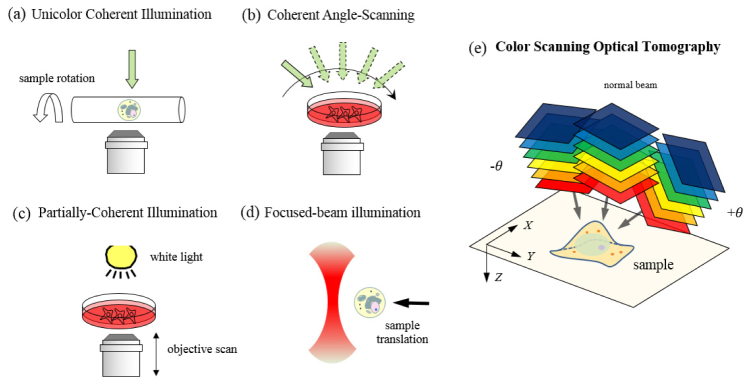
Tomographic optical microscopy in various configurations for three-dimensional refractive index mapping of a specimen: (a) Rotating-sample geometry [13]. (b) Rotating-beam geometry [5,14,15]. (c) Objective-lens-scan geometry [18–21]. (d) Scanning-sample geometry [22,23], and (e) color-scan geometry proposed in this study. The figure (e) also shows the spatial (X,Y,Z) coordinates used for derivation of the formula.
In this paper, we present a unique three-dimensional cell imaging technique that completely obviates the need for scanning optical elements of a microscope. In the proposed method, the depth information is acquired by scanning the wavelength of illumination, which was first proposed in the ultrasound regime [24]. Because scanning the wavelength of a single illumination beam does not provide good depth sectioning, we split the beam into three branches, each of which is collimated and incident onto the specimen at a different angle Fig. 1(e). Both the phase and amplitude images corresponding to the three beams are recorded in a single shot for each wavelength using our novel phase microscope. The wavelength is scanned using an acousto-optic tunable filter whose response time is only tens of microseconds, several orders of magnitude faster than mechanical scanning [25]. In the following sections, we explain the theoretical framework upon which the new technique is founded, and the experimental setup allowing for the measurements required by the theory. Applying our method to polystyrene beads and live biological specimens, we demonstrate the three-dimensional imaging capability of the proposed system for a practically attainable color-scan range of 430 – 630 nm.
2. Scanning color optical tomography
Suppose that we illuminate a sample with a collimated beam at certain wavelength and record the amplitude and phase of the scattered field from the sample. The recorded images will contain the information of the sample’s structure and refractive index. Specifically, the scattered field recorded for a collimated beam of a specific color and illumination angle contains the sample information lying on the Ewald sphere in the spatial frequency space [24]. The arc C in Fig. 2(a) represents a cross-section of the Ewald sphere, where the radius of arc is the inverse of the wavelength and its angular extent is determined by the numerical aperture of the imaging system. Thus by varying the color of illumination, we will retrieve a different portion of the object’s spatial-frequency spectrum. This additional information on the sample effectively improves the three-dimensional imaging capability, as was first explained in the context of ultrasonic tomography [24]. It is important to note that reconstructing the three-dimensional refractive index map of the sample from this mapping in the spatial-frequency space is an ill-posed inverse problem [26], which becomes better posed to solve as we retrieve more regions of the spatial-frequency space by performing additional measurements. One may define the axial resolution of the system as the inverse of the bandwidth or frequency support in the kZ direction. It must be noted that this axial resolution is not necessarily the same for all the transverse frequencies.
Fig. 2.
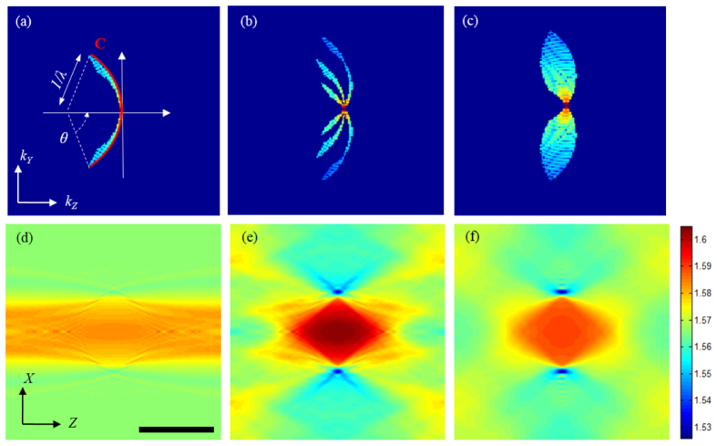
Mapping of the two-dimensional scattered fields in the spatial frequency space for different wavelengths and illumination angles: (a) Single-beam illumination. (b) Three-beam illumination (0, + θ and -θ), and (c) continuous scanning of the illumination angle from –θ to + θ. For this simulation, θ = 32° was used. Figures (d)-(f) are X-Z cross-sections of the refractive index map reconstructed from (a)-(c), respectively. The wavelength is varied from 430 to 630 nm. Imaging objective (60X, NA = 1.2). Scale bar is 10 μm.
Application of the wavelength-scan or color-scan approach for optical microscopy has been discouraged due to the fact that one needs to scan the wavelength over an impractically broad range to achieve reasonably high depth resolution. For a more quantitative assessment of this argument, we simulated three imaging geometries using a 10-μm polystyrene microsphere (immersed in index matching oil of n = 1.56) as a sample. In the first simulation, we assumed that a single collimated beam was incident onto the sample and the illumination wavelength was swept in the range 430 - 630 nm. Figures 2(a) and 2(d) show the vertical cross-sections of retrieved frequency spectrum and reconstructed tomogram, respectively. The spatial-frequency support in Fig. 2(a) is narrow, which explains the elongated shape of bead along the z-direction in Fig. 2(d). Increasing the wavelength range up to 830 nm did not make a visible improvement on the image. This result is consistent with previous studies [27], which showed that wavelength scan alone does not provide the sufficient coverage in the spatial-frequency space. To get around this limitation, we introduce two additional beams to the sample and change their illumination color at the same time. Figure 2(b) shows a cross-section of the retrieved frequency spectrum when three beams are introduced at the angles of 0, + θ and –θ with respect to the optical axis and their colors are changed simultaneously. The reconstructed bead for this case, shown in Fig. 2(e), converges to the true shape of the bead. To make a comparison with the angle-scan tomography, shown in Fig. 1(b), we further simulated the case where the sample was illuminated with a single beam at 530 nm, the average wavelength, and the angle of illumination was varied from –θ to + θ. As one may expect, the retrieved spatial-frequency spectrum in Fig. 2(c) is now continuous, however, the spatial-frequency coverage in the z-direction is comparable to the case of wavelength scan using three beams. This could be also visually seen from a comparison between the extent of the frequency support in the kZ direction for Fig. 2(b) and 2(c).
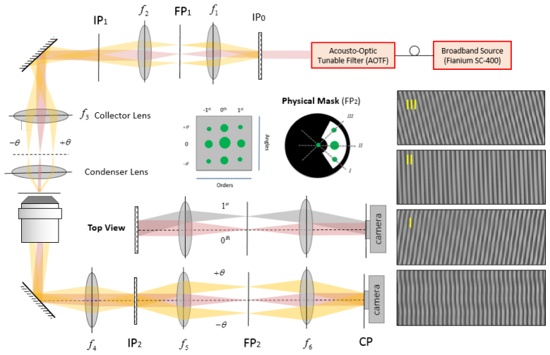
Interferometry-based techniques are highly suitable for measuring the complex amplitude (both amplitude and phase) of the scattered field in the visible range. To record the scattered field of the three incident beams, we built an instrument (Fig. 3) adapted from a Diffraction Phase Microscope (DPM) [28]. Specifically, the output of a broadband source (Fianium SC-400) is tuned to a specific wavelength through a high-resolution acousto-optic tunable filter (AOTF) operating in the range from 400 to 700 nm. The filter bandwidth linearly increases with the wavelength, but stays in the range of 2-7 nm; therefore, we may assume that the illumination used for each measurement is quasi-monochromatic. The output of the AOTF is coupled to a single-mode fiber, collimated and used as the input beam to the setup. A Ronchi grating (40 lines/mm, Edmund Optics Inc.) is placed at a plane (IP0) conjugate to the sample plane (SP) in order to generate three beams incident on the sample at different angles. Note that other than the condenser (Olympus 60 X, NA = 0.8) and the collector lens (f3 = 200 mm) we use a 4F imaging system (f1 = 30 mm, f2 = 50 mm) in order to better adjust the beam diameter and the incident angle on the sample. Using a 4F imaging system also facilitates filtering the beams diffracted by the grating so that only three beams enter the condenser lens. Three collimated beams pass through the microscope objective lens (Nikon 60 X, NA = 1.2) and tube lens (f4 = 200 mm) before arriving at the second Ronchi grating (140 lines/mm, Edmund Optics Inc.) placed at the imaging plane (IP2). There is another 4F imaging system between the grating and the CCD camera (f5 = 100 mm, f6 = 300 mm). The focal lengths of the lenses and the grating period are chosen to guarantee that one period of the grating is imaged over approximately four camera pixels [29]. As shown in Fig. 3, there are nine diffracted orders at the Fourier plane, as opposed to three in the conventional DPM. Three columns correspond to three angles of incidence on the sample while three rows are due to diffraction by the grating in the detection arm. We apply a low-pass filter on the strongest diffracted beam at the center to use it as a reference for the interference. The recorded interferogram provides the information of the sample carried by the three beams. Therefore, the recorded interferogram contains three interference patterns, two of which are oblique (I and III) and the third (II) is vertical. While the three patterns may not be distinguishable in the raw interferogram, one can isolate the information for each incident angle in the spatial frequency domain, i.e., by taking the Fourier transform of the interference pattern.
Fig. 3.
Schematic diagram of the experimental setup: SP (Sample plane); IP (Image plane); FP (Fourier Plane); Condenser lens (Olympus 60 X, NA = 0.8), Objective lens (Nikon 60 X, NA = 1.2). f1 = 30 mm, f2 = 50 mm, f3 = 200 mm, f4 = 200 mm, f5 = 100 mm, and f6 = 300 mm. Non-diffracted order is shown in red while yellow refers to the oblique illumination. Interferograms I, II, and III are decomposition of the raw interferogram (bottom right) into its three components. The physical mask placed at FP2, creates a reference by spatially cleaning the non-diffracted order while passing the 1st order sample beams that correspond to the three incident angles.
3. Data analysis and experimental results
We use an illumination consisting of three beams and record two-dimensional scattered fields after the specimen for different wavelengths. For a monochromatic, plane-wave illumination, the scattered field after specimen can be simply related to the scattering potential f of the specimen in the spatial frequency space. To briefly summarize the theoretical background used for data analysis, the scattering potential is defined as
| (1) |
where λ0 is the wavelength in the vacuum, k0 = 2π/λ0 is the wave number in the free space, nm is the refractive index of surrounding medium, and n(r) is the complex refractive index of the sample [30]. Ignoring the polarization effects of the specimen, the complex amplitude us(r) of the scattered field satisfies the following scalar wave equation,
| (2) |
where k is the wave number in the medium, and u(r) is the total field, which is recorded by the detector, and represents a sum of the incident and scattered field. A more complete theoretical framework taking the vector nature of light in tomographic techniques into account can be found here [14]. When the specimen is weakly scattering, the two-dimensional Fourier transform of the scattered field recorded in various illumination conditions can be mapped onto the three-dimensional Fourier transform of the scattering potential of the object, as was first proposed by E. Wolf [30]:
| (3) |
where F(kX,kY,kZ) is the three-dimensional Fourier transform of scattering potential f(X,Y,Z), and Us(kx,ky;z) is the two-dimensional Fourier transform of the scattered field us(x,y;z) with respect to x and y. The variables kX, kY, and kZ are the spatial frequency components in the object coordinates, while kx, ky and kz refer to the those in the laboratory frame. Therefore, one needs to map the scattered field of the transmitted waves for each illumination condition to the right position in the three-dimensional Ewald’s sphere discussed earlier,
| (4) |
where mx and my are functions of the illumination, which are proportional to the location of of the object’s zero frequencies in the object coordinate. In the case of off-axis interferometry these parameters can be readily calculated using the two-dimensional Fourier transform of the scattered waves, see Fig. 4.
Fig. 4.
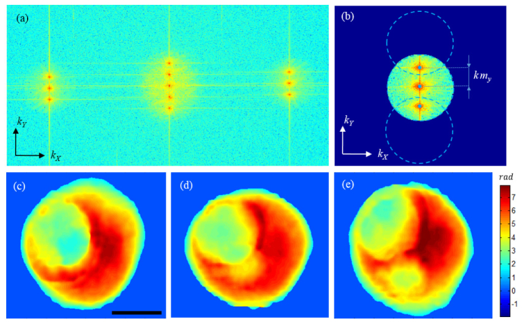
Data processing. (a) Two-dimensional Fourier transform of the raw interferogram, whose magnitude is shown in a logarithmic scale of base 10. (b) Cropping the spatial frequencies using masks defined by the physical numerical aperture. The circles are centered at the object zero frequency location corresponding to the illumination angle. Blue dots show the center points. (c)-(e) Phase maps after unwrapping, which correspond to + θ, normal, -θ beams, respectively. Scale bar is10 μm.
The original formulation in Eq. (3) was derived using the first-order Born approximation., A. Devaney later extended this formulation to allow for the first-order Rytov approximation as well, which resulted in better reconstruction of optically thick specimens [31]. The Rytov formulation use the same equation, Eq. (3), after substituting the scattered field defined as:
| (5) |
where u0(x,y;z) is the incident field. The Rytov approximation is valid when the following criterion is met,
| (6) |
where nδ is the refractive index change within the sample. Therefore, the Rytov approximation is valid when the phase change of propagating light is not large over the wavelength scale. This is in contrast to Born approximation where the total change in the phase itself must be small rather than the phase gradient [24].
In off-axis interferometry adopting a single illumination beam, one can simply extract both the amplitude and phase of the measured field using the Hilbert Transform applied to the raw interferogram [28,32]. In our method adopting three beams, we need to isolate the contribution of each beam prior to retrieving the field information. Figure 4(a) shows the two-dimensional Fourier transform of the raw interferogram that is an autocorrelation of the amplitude leaving the mask in the Fourier plane (FP2). It is interesting to note that unlike the conventional off-axis interferometry where only one diffracted order exists, we have three diffracted beams passing through the physical mask, which create five peaks in the middle of Fig. 4(1) instead of three. The frequency content corresponding to the three beams is initially cropped by a Hanning window Fig. 4(b), the radius of which is determined by the physical numerical aperture of our imaging system. Likewise, a circular mask of the same radius, dotted lines in Fig. 4(b), crops the information corresponding to the oblique illumination beams. The remainder is ascribed to the normal illumination beam. After isolating the frequency content for each illumination angle and shifting the peak, that is the object’s zero frequency, to the origin of spatial-frequency coordinates, one can take the inverse Fourier Transform to retrieve the complex field corresponding to the angle for a specific wavelength. To correct for system aberrations and to separate the scattered fields from the incident field, a set of background images is recorded for an empty region and subtracted from the sample images. These images for background subtraction can be acquired before the measurement, and can be repeatedly used for different samples. Because we record the information of the three illumination angles in a single shot and they all lie within the numerical aperture of the detection objective, there will be a certain degree of overlap for higher spatial-frequency components associated with highly scattered objects. One can potentially account for such a contamination through the use of a priori information about the object and development of a proper algorithm. Implementation of this additional step, however, goes beyond the scope of this specific work. Figure 4(c) through 4(e) show examples of the retrieved phase maps for a hematopoietic stem cell and for the three illumination angles. As explained earlier and in more detail here [33], the complex field information for each incident angle can be mapped onto the object’s spatial-frequency spectrum using Eq. (4). The location of the blue dots relative to the center point determines the parameters mx and my in Eq. (4). As one may expect, since our grating at IP0 diffracts the light only in y-direction, mx = 0 in our setup. Therefore, scanning the color of three beams in our setup provides spatial-frequency coverage similar to scanning the angle of illumination along one direction in angle-scan tomography. This means we may have different resolution in X and Y. For the symmetrical sample used here, however, the X-Z and Y-Z cross sections are similar. After completing the mapping, one can obtain the refractive index map through the three-dimensional inverse Fourier transform.
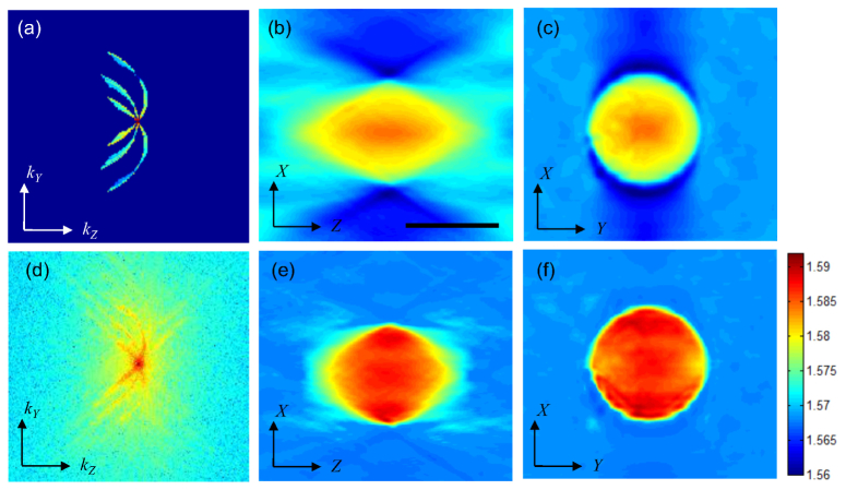
To make a comparison between simulation and experimental data, we conducted experiments on polystyrene microspheres immersed in index matching oil (n = 1.56 at 589.3 nm) in accordance with the simulations done earlier in the previous section. Here it must be noted that in our instrument the illumination angle varies slightly for different wavelengths because of the dispersive nature of the diffraction grating used for creating three illumination beams. The simulation conducted earlier in section 2 reflects this fact where illumination angle has been varied linearly from 24 to 38 degrees with θ = 32° being the average illumination angle. Figure 5(a) shows a vertical cross-section of the spatial-frequency spectrum after completing the mapping of experimental data, which matches well with our simulation; see Fig. 2(b). Figures 5(b) and 5(c) show vertical and horizontal cross-sections, respectively, of the reconstructed tomogram. Optical tomography using a scanning-angle or scanning-objective-lens geometry suffers from the missing cone problem, namely data in the cone-shaped region near the origin of frequency coordinates is not collected, similar to wide-field fluorescence microscopy. Because of this missing information, the reconstructed map is elongated along the optical axis direction and the refractive index value is underestimated. Using a priori information of the object such as non-negativity, we can fill the missing region, suppress the artifacts and improve the quality of reconstruction [33]. Figures 5(e) and 5(f) show vertical and horizontal cross-sections, respectively, of the reconstructed bead after 25 iterations of our regularization algorithm, using non-negativity constraint. In these images, the negative bias around the sample is eliminated and the refractive index value (1.585 ± 0.001) converges to the value obtained with angle-scan tomography and that provided by the manufacturer. It is worth noting that the current algorithm does not compensate for the material dispersion; therefore, the obtained refractive index value is for the mean wavelength. In addition to the non-negativity constraint, we can also use the piecewise-smoothness constraint for further improvement at the cost of additional computation time [34].
Fig. 5.
Spatial-frequency mapping and reconstructed tomogram of a 10 μm Polystyrene bead before/after regularization. (a) Vertical cross-section of the spatial-frequency spectrum before regularization. (b), (c) Reconstructed images in X-Z and X-Y planes, respectively, before regularization. (d) Vertical cross-section of the spatial-frequency spectrum after regularization. (e), (f) Reconstructed images of the bead in X-Z and X-Y planes after regularization. Scale bar is 10 μm.
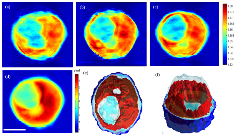
To further demonstrate our method on a biological specimen, we imaged a hematopoietic stem cell (HSC). Study of the morphology and structure of HSCs in a label-free fashion is of particular interest, since labeling would interfere with the differentiation of HSCs and labeled cells cannot be used for therapeutic purposes. A promising result was recently reported, where Chalut et al. demonstrated the use of physical phenotypes acquired with DHM to quantify cellular differentiation of myeloid precursor cells [35]. Figures 6(a) through 6(c) show horizontal cross-sections of the specimen at 2 μm intervals after tomographic reconstruction. The images show varying internal structures at different heights, which clearly demonstrate three-dimensional imaging capability of the proposed method with high axial resolution. As can be seen in Fig. 6(d), these internal structures are not visible in the cumulative phase map or in a single –shot phase image. Figures 6(e) and 6(f) show three-dimensional rendering of the refractive index map at two different angles.
Fig. 6.
Three-dimensional refractive index map of a hematopoietic stem cell: (a)-(c) Horizontal cross-sections of the tomogram at 2 μm intervals. d) Cumulative phase map of the whole cell. (e)-(f) Three-dimensional rendering of the cell using the measured refractive index map, which shows various internal structures. Scale bar is 10 μm.
4. Discussion
For a monochromatic plane wave incident onto a sample, the recorded scattered wave provides only a portion of the spatial-frequency spectrum for the object. Therefore, coherent imaging of complex three-dimensional structures within a specimen requires tomographic data acquisition, namely recording multiple images while varying illumination angles. This is in contrast to the topographic surface measurement [36] or locating a finite number of the scatterers in the three-dimensional space [37], where single-shot imaging may be sufficient. When a light source with reduced spatial coherence [19], temporal coherence, or both [20] is used, the retrieved spatial-frequency spectrum is much broader, but the depth-of-field is significantly reduced. Therefore, one needs to scan the objective focus through the sample to acquire three-dimensional volume data. In this paper, we reported a high-resolution optical microscopy technique using structured illumination of coherent light and wavelength scanning to increase the axial resolution. The idea of changing of the source frequency for better axial resolution was originally proposed decades ago in ultrasonic tomography [24]. However, application of the idea for high-resolution optical microscopy has been discouraged on the grounds that the frequency coverage achieved through wavelength scanning is not sufficient [27]. Our hybrid approach resolves this problem by combining three illumination angles with wavelength scanning to acquire high axial resolution for a practically attainable wavelength range. Using an experimental setup extending the concept of DPM, we recorded the complex amplitude of the scattered field for three illumination beams for each wavelength.
In existing tomographic microcopy, scanning mirrors or moving the focus of objective lens is a barrier for increasing the speed of data acquisition. The method we propose scans the wavelength through an acousto-optic tunable filter, whose transition time is only tens of microseconds. By introducing three beams simultaneously, we can reduce the sampling number by a factor of three as well. In this initial work, we record tomograms in about one second due to limited wavelength switching speed afforded by the manufacturer software, however, this limit can be pushed by orders of magnitude by implementing proper hardware control algorithm and a faster imaging device. We can thereby acquire interferograms required for a single tomogram within milliseconds using a high-speed camera. We also note that the methods included in this report do not correct for material dispersion, which may become noticeable for certain biological specimens in the visible region. For example, the refractive index of the hemoglobin in red blood cells has a strong wavelength dependence in the 355-500 nm range [38]. Nucleic acids have a clearly distinct refractive index profile from proteins at the wavelength close to their absorption peaks [39]. Our method collects images in a broad range of wavelength, each of which contains both material dispersion information as well as structural information of the sample. Extracting material dispersion of the cellular organelles, which is left for a future study, could provide rich molecular-specific information, e.g., relative amount of nucleic acids and proteins, at a subcellular level [4].
Acknowledgments
This work was mainly supported by NIH 9P41EB015871-26A1 and 1R01HL121386-01A1. Peter T.C. So was supported by 5P41EB015871-30, 5R01HL121386-03, 2R01EY017656-06A1, 1U01NS090438-01, 1R21NS091982-01, 5R01NS051320, DP3DK101024-01, 4R44EB012415-02, NSF CBET-0939511, the Singapore-MIT Alliance for Science and Technology Center, the MIT SkolTech initiative, the Hamamatsu Corp. and the Koch Institute for Integrative Cancer Research Bridge Project Initiative. The authors would like to thank Professor George Barbastathis for helpful discussion, and Dr. Jeon Woong Kang for sample preparation and feedback on the manuscript.
References and links
- 1.Barer R., “Refractometry and interferometry of living cells,” J. Opt. Soc. Am. 47(6), 545–556 (1957). 10.1364/JOSA.47.000545 [DOI] [PubMed] [Google Scholar]
- 2.Popescu G., Park Y., Lue N., Best-Popescu C., Deflores L., Dasari R. R., Feld M. S., Badizadegan K., “Optical imaging of cell mass and growth dynamics,” Am. J. Physiol. Cell Physiol. 295(2), C538–C544 (2008). 10.1152/ajpcell.00121.2008 [DOI] [PMC free article] [PubMed] [Google Scholar]
- 3.Sung Y., Tzur A., Oh S., Choi W., Li V., Dasari R. R., Yaqoob Z., Kirschner M. W., “Size homeostasis in adherent cells studied by synthetic phase microscopy,” Proc. Natl. Acad. Sci. U.S.A. 110(41), 16687–16692 (2013). 10.1073/pnas.1315290110 [DOI] [PMC free article] [PubMed] [Google Scholar]
- 4.Sung Y., Choi W., Lue N., Dasari R. R., Yaqoob Z., “Stain-free quantification of chromosomes in live cells using regularized tomographic phase microscopy,” PLoS One 7(11), e49502 (2012). 10.1371/journal.pone.0049502 [DOI] [PMC free article] [PubMed] [Google Scholar]
- 5.Choi W., Fang-Yen C., Badizadegan K., Oh S., Lue N., Dasari R. R., Feld M. S., “Tomographic phase microscopy,” Nat. Methods 4(9), 717–719 (2007). 10.1038/nmeth1078 [DOI] [PubMed] [Google Scholar]
- 6.Freudiger C. W., Min W., Saar B. G., Lu S., Holtom G. R., He C., Tsai J. C., Kang J. X., Xie X. S., “Label-free biomedical imaging with high sensitivity by stimulated Raman scattering microscopy,” Science 322(5909), 1857–1861 (2008). 10.1126/science.1165758 [DOI] [PMC free article] [PubMed] [Google Scholar]
- 7.Tong L., Liu Y., Dolash B. D., Jung Y., Slipchenko M. N., Bergstrom D. E., Cheng J.-X., “Label-free imaging of semiconducting and metallic carbon nanotubes in cells and mice using transient absorption microscopy,” Nat. Nanotechnol. 7(1), 56–61 (2011). 10.1038/nnano.2011.210 [DOI] [PubMed] [Google Scholar]
- 8.Mir M., Wang Z., Shen Z., Bednarz M., Bashir R., Golding I., Prasanth S. G., Popescu G., “Optical measurement of cycle-dependent cell growth,” Proc. Natl. Acad. Sci. U.S.A. 108(32), 13124–13129 (2011). 10.1073/pnas.1100506108 [DOI] [PMC free article] [PubMed] [Google Scholar]
- 9.Cooper K. L., Oh S., Sung Y., Dasari R. R., Kirschner M. W., Tabin C. J., “Multiple phases of chondrocyte enlargement underlie differences in skeletal proportions,” Nature 495(7441), 375–378 (2013). 10.1038/nature11940 [DOI] [PMC free article] [PubMed] [Google Scholar]
- 10.Chalut K. J., Kulangara K., Wax A., Leong K. W., “Stem cell differentiation indicated by noninvasive photonic characterization and fractal analysis of subcellular architecture,” Integr Biol (Camb) 3(8), 863–867 (2011). 10.1039/c1ib00003a [DOI] [PubMed] [Google Scholar]
- 11.Creath K., “Phase-measurement interferometry techniques,” Prog. Opt. 26, 349–393 (1988). 10.1016/S0079-6638(08)70178-1 [DOI] [Google Scholar]
- 12.Reed Teague M., “Deterministic phase retrieval: a Green’s function solution,” J. Opt. Soc. Am. 73(11), 1434–1441 (1983). 10.1364/JOSA.73.001434 [DOI] [Google Scholar]
- 13.Charrière F., Marian A., Montfort F., Kuehn J., Colomb T., Cuche E., Marquet P., Depeursinge C., “Cell refractive index tomography by digital holographic microscopy,” Opt. Lett. 31(2), 178–180 (2006). 10.1364/OL.31.000178 [DOI] [PubMed] [Google Scholar]
- 14.Lauer V., “New approach to optical diffraction tomography yielding a vector equation of diffraction tomography and a novel tomographic microscope,” J. Microsc. 205(2), 165–176 (2002). 10.1046/j.0022-2720.2001.00980.x [DOI] [PubMed] [Google Scholar]
- 15.Isikman S. O., Bishara W., Mavandadi S., Yu F. W., Feng S., Lau R., Ozcan A., “Lens-free optical tomographic microscope with a large imaging volume on a chip,” Proc. Natl. Acad. Sci. U.S.A. 108(18), 7296–7301 (2011). 10.1073/pnas.1015638108 [DOI] [PMC free article] [PubMed] [Google Scholar]
- 16.Kim K., Yaqoob Z., Lee K., Kang J. W., Choi Y., Hosseini P., So P. T., Park Y., “Diffraction optical tomography using a quantitative phase imaging unit,” Opt. Lett. 39(24), 6935–6938 (2014). 10.1364/OL.39.006935 [DOI] [PMC free article] [PubMed] [Google Scholar]
- 17.Hsu W.-C., Su J.-W., Tseng T.-Y., Sung K.-B., “Tomographic diffractive microscopy of living cells based on a common-path configuration,” Opt. Lett. 39(7), 2210–2213 (2014). 10.1364/OL.39.002210 [DOI] [PubMed] [Google Scholar]
- 18.Bon P., Aknoun S., Savatier J., Wattellier B., Monneret S., “Tomographic incoherent phase imaging, a diffraction tomography alternative for any white-light microscope,” Proc. SPIE 8589, 858918 (2013). 10.1117/12.2003426 [DOI] [Google Scholar]
- 19.Bon P., Aknoun S., Monneret S., Wattellier B., “Enhanced 3D spatial resolution in quantitative phase microscopy using spatially incoherent illumination,” Opt. Express 22(7), 8654–8671 (2014). 10.1364/OE.22.008654 [DOI] [PubMed] [Google Scholar]
- 20.Kim T., Zhou R., Mir M., Babacan S. D., Carney P. S., Goddard L. L., Popescu G., “White-light diffraction tomography of unlabelled live cells,” Nat. Photonics 8(3), 256–263 (2014). 10.1038/nphoton.2013.350 [DOI] [Google Scholar]
- 21.Fiolka R., Wicker K., Heintzmann R., Stemmer A., “Simplified approach to diffraction tomography in optical microscopy,” Opt. Express 17(15), 12407–12417 (2009). 10.1364/OE.17.012407 [DOI] [PubMed] [Google Scholar]
- 22.Lue N., Choi W., Popescu G., Badizadegan K., Dasari R. R., Feld M. S., “Synthetic aperture tomographic phase microscopy for 3D imaging of live cells in translational motion,” Opt. Express 16(20), 16240–16246 (2008). 10.1364/OE.16.016240 [DOI] [PMC free article] [PubMed] [Google Scholar]
- 23.Sung Y., Lue N., Hamza B., Martel J., Irimia D., Dasari R. R., Choi W., Yaqoob Z., So P., “Three-dimensional holographic refractive-index measurement of continuously flowing cells in a microfluidic channel,” Phys. Rev. Appl. 1(1), 014002 (2014). 10.1103/PhysRevApplied.1.014002 [DOI] [PMC free article] [PubMed] [Google Scholar]
- 24.A. C. Kak and M. Slaney, Principles of Computerized Tomographic Imaging (Siam, 1988), Vol. 33. [Google Scholar]
- 25.Fang-Yen C., Choi W., Sung Y., Holbrow C. J., Dasari R. R., Feld M. S., “Video-rate tomographic phase microscopy,” J. Biomed. Opt. 16(1), 011005 (2011). 10.1117/1.3522506 [DOI] [PMC free article] [PubMed] [Google Scholar]
- 26.J. Hadamard, Lectures on Cauchy’s Problem in Linear Partial Differential Equations (Courier Corporation, 2014). [Google Scholar]
- 27.Dändliker R., Weiss K., “Reconstruction of the three-dimensional refractive index from scattered waves,” Opt. Commun. 1(7), 323–328 (1970). 10.1016/0030-4018(70)90032-5 [DOI] [Google Scholar]
- 28.Popescu G., Ikeda T., Dasari R. R., Feld M. S., “Diffraction phase microscopy for quantifying cell structure and dynamics,” Opt. Lett. 31(6), 775–777 (2006). 10.1364/OL.31.000775 [DOI] [PubMed] [Google Scholar]
- 29.G. Popescu, Quantitative Phase Imaging of Cells and Tissues (McGraw Hill Professional, 2011). [Google Scholar]
- 30.Wolf E., “Three-dimensional structure determination of semi-transparent objects from holographic data,” Opt. Commun. 1(4), 153–156 (1969). 10.1016/0030-4018(69)90052-2 [DOI] [Google Scholar]
- 31.Devaney A. J., “Inverse-scattering theory within the Rytov approximation,” Opt. Lett. 6(8), 374–376 (1981). 10.1364/OL.6.000374 [DOI] [PubMed] [Google Scholar]
- 32.Ikeda T., Popescu G., Dasari R. R., Feld M. S., “Hilbert phase microscopy for investigating fast dynamics in transparent systems,” Opt. Lett. 30(10), 1165–1167 (2005). 10.1364/OL.30.001165 [DOI] [PubMed] [Google Scholar]
- 33.Sung Y., Choi W., Fang-Yen C., Badizadegan K., Dasari R. R., Feld M. S., “Optical diffraction tomography for high resolution live cell imaging,” Opt. Express 17(1), 266–277 (2009). 10.1364/OE.17.000266 [DOI] [PMC free article] [PubMed] [Google Scholar]
- 34.Sung Y., Dasari R. R., “Deterministic regularization of three-dimensional optical diffraction tomography,” J. Opt. Soc. Am. A 28(8), 1554–1561 (2011). 10.1364/JOSAA.28.001554 [DOI] [PMC free article] [PubMed] [Google Scholar]
- 35.Chalut K. J., Ekpenyong A. E., Clegg W. L., Melhuish I. C., Guck J., “Quantifying cellular differentiation by physical phenotype using digital holographic microscopy,” Integr Biol (Camb) 4(3), 280–284 (2012). 10.1039/c2ib00129b [DOI] [PubMed] [Google Scholar]
- 36.Zhang S., “Recent progresses on real-time 3D shape measurement using digital fringe projection techniques,” Opt. Lasers Eng. 48(2), 149–158 (2010). 10.1016/j.optlaseng.2009.03.008 [DOI] [Google Scholar]
- 37.Brady D. J., Choi K., Marks D. L., Horisaki R., Lim S., “Compressive holography,” Opt. Express 17(15), 13040–13049 (2009). 10.1364/OE.17.013040 [DOI] [PubMed] [Google Scholar]
- 38.Friebel M., Meinke M., “Model function to calculate the refractive index of native hemoglobin in the wavelength range of 250-1100 nm dependent on concentration,” Appl. Opt. 45(12), 2838–2842 (2006). 10.1364/AO.45.002838 [DOI] [PubMed] [Google Scholar]
- 39.Fu D., Lu F.-K., Zhang X., Freudiger C., Pernik D. R., Holtom G., Xie X. S., “Quantitative chemical imaging with multiplex stimulated Raman scattering microscopy,” J. Am. Chem. Soc. 134(8), 3623–3626 (2012). 10.1021/ja210081h [DOI] [PMC free article] [PubMed] [Google Scholar]


