Abstract
Accessing the venous bloodstream to deliver fluids or obtain a blood sample is the most common clinical routine practiced in the U.S. Practitioners continue to rely on manual venipuncture techniques, but success rates are heavily dependent on clinician skill and patient physiology. In the U.S., failure rates can be as high as 50% in difficult patients, making venipuncture the leading cause of medical injury. To improve the rate of first-stick success, we have developed a portable autonomous venipuncture device that robotically servos a needle into a suitable vein under image guidance. The device operates in real time, combining near-infrared and ultra-sound imaging, image analysis, and a 7-degree-of-freedom (DOF) robotic system to perform the venipuncture. The robot consists of a 3-DOF gantry to image the patient's peripheral forearm veins and a miniaturized 4-DOF serial arm to guide the cannula into the selected vein under closed-loop control. In this paper, we present the system architecture of the robot and evaluate the accuracy and precision through tracking, free-space positioning, and in vitro phantom cannulation experiments. The results demonstrate sub-millimeter accuracy throughout the operating workspace of the manipulator and a high rate of success when cannulating phantom veins in a skin-mimicking tissue model.
Keywords: Computer vision, kinematics, mechanism design, medical robots and systems, visual servoing
I. Introduction
VENIPUNCTURE is critical to a plethora of clinical interventions and is the most ubiquitous invasive routine in the U.S., with over 2.7 million procedures performed daily [1], [2]. The procedure is traditionally guided by visual inspection and palpation of the peripheral forearm veins. Once a suitable vein is located, a needle is then inserted into the center of the vessel. Oftentimes, however, it is difficult to estimate the depth of the vein or steer the needle if the vein moves or rolls. In these situations, it is easy for the needle tip to slip and miss the vein or pierce through the back of the vein wall. Poorly introduced needles may then result in complications such as increased pain, internal bleeding, or extravasation.
The challenges of venipuncture are exacerbated in obese and dark-skinned patients where locating a vein can be difficult, as well as in pediatric and geriatric populations where the veins are often small and weak. In total, failure rates are reported to occur in 30–50% of attempts [2]. Repeated failure to start an intravenous (IV) line may necessitate alternative pathways such as central venous catheters or peripherally inserted central catheters [3] that incur a much greater safety risk to the patient and practitioner, as well as added time and cost to the procedure [3], [4]. Consequently, venipuncture is the number one cause of patient and clinician injury in the U.S. [2], [5]. In total, difficult venous access is estimated to cost the U.S. health care system $4.7 billion annually [6].
In recent years, various imaging technologies based on ultra-sound (US) [7], visible (VIS) light [8], or near-infrared (NIR) light [9] have been introduced to aid clinicians in finding veins. However, these technologies rely on the clinician to insert the cannula manually. Furthermore, systems that provide 2-D images of the skin, such as the commercially available VeinViewer (Christie Medical Holdings Inc.) and the AV400 System (AccuVein Inc.), do not provide depth information and lack the resolution to detect subtle vessel movement or rolling. Overall, research findings have been mixed regarding the efficacy of imaging devices, with several studies observing no signifi-cant differences in first-stick success rates, number of attempts, or procedure times in comparison with standard venipuncture [10], [11]. The absence of clinical improvement may suggest that difficult insertion of the cannula, instead of the initial localization of the vein, is the primary cause of failure during venous cannulation.
In addition to vein viewing devices, medical robots that automate the needle insertion process have been developed for a wide range of medical applications [12]; however, these devices are not appropriate for venous access. Specifically, surgical robots for prostatectomy [13], orthopedic surgery [14], neurosurgery [15], and brachytherapy [16], [17] are large, complex, and expensive. Several research groups have developed semiautomated venipuncture devices [18], [19]; however, these systems do not remove human error from the procedure, as the clinician is still manipulating the device into position for the needle insertion.
Currently, there are two devices designed to perform automated image-guided venipuncture. The first is an industrialsized robotic arm (VeeBot), which has been reported to locate a suitable vein about 83% of the time [20]. However, these data exclude accuracy rates for the actual robotic needle insertion and have not been published in a peer-reviewed journal. Furthermore, the size and weight of the robotic arm may limit the clinical usability of the system.
The other system designed for automated venipuncture, developed by our group, is the VenousPro device—a portable image-guided robot for autonomous peripheral venous access. A first-generation (first-gen) prototype was introduced in [21], which utilized 3-D NIR imaging to guide a 4-degree-of-freedom (DOF) robot. The system was shown to significantly increase vein visualization compared with a clinician and to cannulate a phlebotomy training arm with 100% accuracy. Nevertheless, while the first-gen device was successful in demonstrating proof of concept, several limitations were observed. First, the device lacked three critical degrees of motion needed to adapt the cannulation procedure to human physiological variability. Namely, the ability to: 1) align the needle along the longitudinal axis of any chosen vein; 2) gradually adjust the angle of the needle during the insertion process; and 3) adjust the vertical height of the needle manipulator.
The second limitation of the device was that it did not incorporate closed-loop needle steering to account for subtle arm and tissue motion. Third, the device required manual camera-to-robot calibration prior to the procedure. Fourth, the device relied on manual handling of the needle by the practitioner and, thus, could not address the risks associated with accidental needle stick injuries. Finally, the imaging capability of the device was found to be reduced in pediatric and high-BMI patients due to the limited resolution of optical techniques alone.
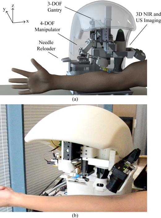
To address the limitations of the first-gen prototype, a second generation (second-gen) device (see Fig. 1) has been developed. This device incorporates 7-DOF, including the original 4-DOF of the first-gen device and three added DOF that dramatically extend the kinematics and operating workspace for the needle insertion task. The major mechanical enhancement of the second-gen device is the implementation of a miniaturized 4-DOF serial manipulator arm that steers the needle under closed-loop kinematic and image-guided controls. Additionally, US imaging has been incorporated into the new device to improve vein visualization in patient demographics that challenged the original system.
Fig. 1.
(a) Design and (b) prototype of the automated venipuncture robot.
This paper focuses on the robotic design, implementation, and testing of the second-gen venipuncture device, with particular focus on the kinematics and closed-loop control of the miniaturized 4-DOF needle manipulator. The reader is referred to [21] for in-depth details of the image-processing algorithms. Here, we first describe detailed designs of the robot in Sections II–IV and, then, present experimental tracking, positioning, and phantom cannulation results in Section V. Finally, Section VI draws conclusions and presents future work.
II. Device Design
Table I outlines the high-level design criteria that guided the development of the second-gen device. Fig. 1(a) illustrates a rendered CAD model of the system, which combines NIR and US imaging, a 3-DOF gantry system, and a 4-DOF manipulator. Fig. 1(b) shows the physical device, which is significantly smaller than the first-gen device (30 × 25 × 25 cm, 3.5 kg versus 46 × 46 × 46 cm, 10 kg). The open half-shell design allows the device to be easily integrated into the existing phlebotomy work flow.
TABLE I.
Summary of Design Requirements and Engineering Constraints
| Design Criteria | Engineering Constraint |
|---|---|
| Accuracy | Cannulate ø2.0–3.5 mm veins |
| Imaging depth | Image veins up to 10 mm deep |
| Real-time tracking | Segment and track veins at > 15 Hz loop rate |
| Size & weight | Portable (< 30×30×30 cm) & lightweight (< 10 kg) |
| Time of procedure | Perform the venipuncture in < 5min |
This process starts with the clinician first swabbing the injection site with alcohol, either in the antecubital fossa (for blood draws) or anterior forearm (for IV therapy). The clinician then loads the cannula into the back of the device with the cap still in place. The robot arm grabs the needle using an electromagnet (EM) embedded in the end-effector, and as the manipulator translates horizontally in the y-direction, the cap is removed.
Once the needle is loaded, the patient places their arm in the device, which incorporates an arm rest that lightly restrains the arm via an adjustable handle bar to reduce large movements. The NIR imaging system and image analysis software, which then scans the arm and segments the veins, is described in detail in [21]. Briefly, the device uses 940-nm NIR light to improve the contrast of subcutaneous peripheral veins and extracts the 3-D spatial coordinates of the segmented veins from images acquired by a pair of calibrated stereo cameras. Suitable veins, selected based on continuity, length, and vessel diameter [21], are displayed on the device's user interface (UI), from which the clinician selects the final cannulation site. Then, the US probe lowers down on the patient's arm to provide a magnified longitudinal image of the chosen vein and confirms venous blood flow. Finally, the robot aligns the cannula along the longitudinal axis of the vein and inserts the needle at 30°, as commonly observed in the clinic. The manipulator then gradually lowers the insertion angle to 15° upon contact with the skin surface, until the tip reaches the center of the vein.
Once securely positioned in the vessel, the cannula disengages from the robot, and by virtue of the open shell design, the clinician can access the patient's arm to finish the procedure. In the case of a blood draw, this includes interchanging blood vials, removing and disposing of the needle, and placing a bandage over the injection site.
The UI allows the clinician to oversee the full robotic venipuncture and intervene if necessary. In addition, the UI directs the clinician through the protocol steps by prompting checks and reminders to ensure that both the patient and practitioner remain safe throughout the phlebotomy. The total procedure time using the robot is estimated to be <5 min for all patients, where the system executes the steps from imaging the veins to cannulating the vessel in <2 min [21]. Compared with manual phlebotomy, where the time to completion can range from 7 min in normal adult patients to >30 min in difficult populations [22], the robot has the potential to perform the cannulation in significantly less time.
III. System Architecture
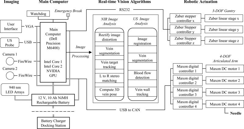
The key elements in the system architecture are broadly categorized into the imaging component, main computer, image-processing unit, and robotic assembly (see Fig. 2), each with their respective safety mechanisms. For example, we implemented a watchdog protocol to monitor the activity of the processing unit, controls, and electronics. In addition, all actuators have nonbackdrivable gear heads that lock in position when torque is removed to ensure no free motion at the robot joints. Finally, there is a push-button brake that shuts down the electrical hardware to lock the joints, located by the UI.
Fig. 2.
Hardware and software system architecture design, depicting the process flow from image acquisition, signal processing, and robotic controls.
A. Hardware
The device is fabricated out of 6061 machined aluminum, rapid prototyped ABS thermoplastic, precision ball bearing linear sliders, as well as off-the-shelf electronic components including actuators, motor drivers, LEDs, and the US probe.
1) Optical and Ultrasound Image Acquisition
The device exploits the unique properties of the NIR spectrum (700–1000 nm) to image the subcutaneous veins. Namely, NIR light exhibits decreased scatter and reflection on the skin tissue surface compared to VIS light, and deoxyhemoglobin in veins shows increased absorption in the NIR range [23]. This results in a 4-mm NIR penetration depth that highlights the contrast of superficial veins. However, in obese and pediatric populations whose veins often lay underneath a dense layer of adipose tissue, NIR light is unable to image the vessels. Thus, we implemented US imaging to increase the penetration depth to 4 cm, ensuring that the device can be used across all demographic groups.
The imaging subassembly consists of two charge-coupled device cameras (Firefly MV, Point Grey) with extended sensitivity in the NIR spectrum, as well as a 12-MHz brightness mode (B-mode) portable US transducer (Interson Inc.). The cameras provide a coarse 3-D map of the venous structure, and once a suitable injection site is selected, the US probe drops down to provide a high magnification longitudinal view of the chosen vein. Wide-angle (100°) lenses are fitted to each camera to enable a sufficient field-of-view to image peripheral forearm veins (wrist to 4 cm proximal to the elbow). The cameras and US probe are securely mounted to the 3-DOF gantry system via machined aluminum brackets. NIR images are captured at 30 Hz each and transmitted to the GPU for processing. The US probe operates at 20 frames/s, enabling the 256 acoustic scan lines to be processed in real time. The resolution of the NIR image is 1 mm in x and y, and 2 mm in z, whereas the resolution in the US image is 0.015 mm in x and z.
2) Seven-Degree-of-Freedom Robot
The robotic system is comprised of a 3-DOF Cartesian gantry (x, y, z as depicted in Fig. 1) and a 4-DOF serial needle manipulator arm. Precision lead-screw linear stages are used for the Cartesian positioning system (LSM series, Zaber), whereas DC brushed motors with gear heads and magnetic-based incremental encoders (A-max 16, Maxon Motors) are used for the 4-DOF serial arm. Translation in x and y positions the US probe and needle manipulator above the injection site, and z translation allows the US probe to lower onto the patient's arm. The linear stages are driven by NEMA 08, two-phase stepper motors (Zaber) with a resolution of 0.1905 μm, peak thrust of 25 N, max speed of 5.8 cm/s, and minimal backlash (<13 μm)—satisfying the power and precision requirements needed for each axis. The steppers operate under open-loop control using dedicated motor drivers for each stage with 1/64 step resolution.
The serial arm provides longitudinal alignment along the vein, positions the needle at a 30° insertion angle, and performs the injection using a linear spindle drive (RE 8, Maxon Motors). Motor torque and power calculations governed the selection of low-backlash (<0.3°) gear head motors for joints 1–3 (see Fig. 4) and a linear spindle drive for the injection system. The joint motors can supply up to 30 N · cm of torque, with a closed-loop positioning resolution of 0.002°, by means of the attached 512 cpt quadrature encoders. Conversely, the spindle drive outputs a max force of 8 N, which has been shown to be sufficient to pierce human skin tissue and the vein wall [18]. An EM (EM050, APW Company) with a 9-N holding force is embedded in the distal end of the end-effector to serve as the needle attach and release mechanism.
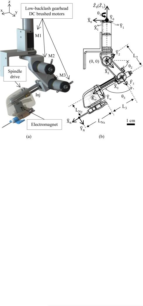
Fig. 4.
(a) Design and (b) kinematic joint frames of the 4-DOF serial arm. Coordinate axis in (a) corresponds to the notation of the 3-DOF gantry.
3) Central Processor
A compact PC (Dell Precision M6400) in conjunction with a graphics card (NVIDIA Quadro FX 3700M) was utilized for all experiments conducted in this study. The graphics processor handles the majority of the image-processing pipeline as outlined in Fig. 2, whereas the CPU handles the robotic kinematic controls and UI display. Currently, we are working to replace the laptop CPU and GPU with an embedded system to reduce the size of the central processor.
B. Software
Calibration of the NIR and US imaging systems, as well as the vision algorithms used to guide the robot, are summarized below. All vision and motion control software was written in LabVIEW (National Instruments) and C++.
1) Automated Stereo Camera Calibration
Camera calibration software was adapted from the Caltech Toolbox [24] and rewritten in LabVIEW. A planar grid with circular control points was machined to the base of the system. During the calibration, the grid is imaged by the stereo camera pair at different viewing heights to form a nonplanar cubic calibration rig. The cameras were positioned vertically by the z-axis of the 3-DOF gantry system. The intrinsic and extrinsic parameters of the stereo setup are then extracted using the method of Heikila [25], allowing the camera coordinates to be registered to the robot frame. The resulting reprojection error is approximately ±0.1 mm in our setup, which translates to an (x, y, z) image reconstruction error of approximately 1 mm, given the image resolution of the cameras.
2) Automated Ultrasound Calibration
In order to register the US system to the robot frame, the curvilinear coordinate system of the US transducer must be converted to the rectangular coordinate system of the image displayed on-screen. In this process of scan conversion, the raw B-mode scan lines extracted from the curved US transducer are spatially interpolated based on the known geometry of the transducer, sampling frequency, and line density [26]. Small spatial errors in the scan conversion are then minimized using an N-shaped fiducial-based calibration method [27], which allows the pixel coordinates of the US image to be mapped back to the robot coordinates.
3) Vein Segmentation and Image Guidance
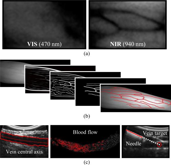
Image analysis algorithms for the NIR and US systems are executed in parallel on a GPU to increase the cycle rate (see Fig. 2, center). Fig. 3 outlines the main image analysis steps, as detailed in [21]. Briefly, veins are first extracted from the NIR images by analyzing their second-order geometry [28]. Suitable veins, determined based on their diameter, length, continuity, and contrast, are displayed on the UI for selection by the practitioner via clinical judgment. During the needle insertion, the selected vein is segmented in real time from the longitudinal US image using the region growing algorithm in [29]. The center of the segmented vein is then calculated continuously at high resolution (0.015 mm), allowing the exact depth of the cannulation target to be known throughout the insertion. The US image can also be used to detect blood flow within the veins and visualize the needle.
Fig. 3.
Overview of the software scheme. (a) VIS versus NIR light, demonstrating increased vein contrast in NIR light. (b) NIR image-processing steps from raw image (left) to segmented veins (right). (c) From left to right: US longitudinal segmentation, blood flow detection, and needle visualization.
IV. Needle Manipulator
A. Serial Arm Design
The needle manipulator on the first-gen device consisted of a 2-DOF mechanism to 1) set the insertion angle, and 2) cannu-late the selected vein under NIR guidance. All actuators were stepper-based and operated under open-loop commands; hence, the motors could not provide real-time feedback control to locate the needle tip via forward kinematics. Furthermore, with only one revolute DOF, the manipulator had a highly limited operating workspace and was unable to align the needle with the orientation of the vein.
To address these problems, we redesigned the needle manipulator in the second-gen device based on the following engineering constraints.
-
1)
The manipulator should have the accuracy to cannulate veins as small as ø2 mm (seen in pediatric populations).
-
2)
The needle insertion force should be >5 N (shown to be sufficient to pierce human skin tissue [18]).
-
3)
The robotic arm should be compact (<30 cm3) and lightweight (<0.4 kg).
-
4)
The manipulator should have an operating workspace >175 cm3 (sufficient for the needle insertion task [21]).
-
5)
The end-effector should have a safety quick release mechanism to disengage the cannula from the robot.
Several robot designs were considered, including parallel, serial, and decoupled systems. Although parallel robots offer high accuracy, stiffness, and low inertia, oftentimes the workspace of a parallel manipulator is smaller than the robot itself. The needle manipulator on our device needs to be compact, yet have a large enough workspace to align and reach all possible vein injection sites on the forearm (i.e., workspace volume >175 cm3). Decoupled systems often involve complex mechanisms and are constrained to disjointed motions. To achieve a large enough workspace with a decoupled manipulator, the system would have to be large and bulky, thus increasing the size and weight of our device.
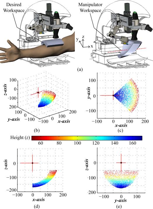
Conversely, a serial arm can provide a large enough workspace using simple compact mechanisms, while also allowing for smooth human-like joint trajectories. For these reasons, we selected a serial manipulator arm to servo the needle. Fig. 4 illustrates the robotic arm concept and corresponding kinematic link chains. A compact serial arm design also allows the device to keep the needle hidden from the patient at all times prior to the venipuncture. When folded in its home position, the manipulator has a volume of 2 × 2 × 6 cm, yet once fully extended, the needle can reach points as far as 16 cm from the robot arm origin (see Fig. 5).
Fig. 5.
(a) Desired (left) and dexterous (right) workspace of the manipulator highlighted in gray in the CAD model. Dotted red line in the manipulator workspace image indicates that the workspace can be translated ±50 mm along x to adjust to the patient's arm size. (b)–(e) Manipulator operating workspace from the serial arm origin with practical limits set on the M1 joint rotation (±45°) and z height (z <−20 mm). Plotting units are in mm.
Complex manipulator-mechanism designs such as cables and pulleys that are commonly seen in surgical robots were avoided in the serial arm to keep the joints compact and stiff. Instead, low-backlash (<0.3°) precision gear heads (GS16VZ, Maxon Motors) are integrated into the motors, and the outputs of the gear axles are directly attached to each rotational link in the manipulator chain. For the linear injection system, we use a spindle drive to provide smooth linear motion, while minimizing backlash (1.8° corresponding to 0.112-mm positioning accuracy).
B. Kinematics
Forward kinematics is used to extract the needle tip position from the joint parameters, whereas inverse kinematics is used to calculate the joint angles required to position the needle tip at the desired location. The kinematic equations for the manipulator arm were derived using a standard Denavit–Hartenberg (DH) convention [30]. Fig. 4(b) shows the assignment of link frames, and Table II contains the DH parameters used to solve the kinematic equations.
TABLE II.
DH Parameters of the 4-DOF Robotic Arm Kinematic Chain
| i | α i–1 | a i–1 | di | θ i |
|---|---|---|---|---|
| 1 | 0 | 0 | 0 | θ 1 |
| 2 | 90° | 0 | 0 | θ 2 |
| 3 | 0 | 0 | L 2 | θ 3 |
| W | 0 | 0 | L 3 | 0 |
The parameters specified in the DH table link the manipulator origin frame to the wrist frame at the distal end of the end-effector as governed by (1). The needle tip position is then computed using a wrist-to-tool transform
| (1) |
Using (1), the operating workspace was computed to be 310 cm3 for the needle manipulator and is displayed in Fig. 5. The length of links 2 and 3 were optimized by running kinematic simulations so that the volume of reachable workspace was sufficient for the needle insertion task (i.e., 175 cm3 as governed by a clinical survey [21]).
C. Motor Control System
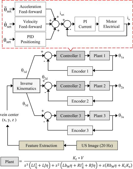
As depicted in Fig. 6, the motor control scheme is as follows. First, the 3-D coordinates of the selected target vein center are outputted from the US vein segmentation algorithm and inputted into the inverse kinematic equations. Here, the joint parameters needed to position the needle at the desired location prior to the cannulation are calculated. The manipulator has the ability to dynamically steer the needle in real time by tracking the injection site and vein walls in the US image to account for patient arm movement, vein/tissue deformation, and vein rolling. Specifically, we use a trajectory planner that calculates the needle path, interpolating from the start and end points at a 20-Hz cycle rate using an exponential decay function. This allows us to continuously feedback the updated desired injection site extracted from the US image. In this fashion, the US serves as image feedback to guide the needle manipulator in a closed-form control loop.
Fig. 6.
Motor position feedback control scheme for the 4-DOF serial arm. The 3-D target injection site is updated from the US at 20 Hz. Plants 1–3 have different rotational inertias (I1 = 9057, I2 = 2000, I3 = 700 g · cm2)
During the cannulation, the insertion angle is gradually decreased from 30° to 15° following contact with the skin surface. Here, the cannula is steered into the vein until the needle tip reaches the center. By tracking the target vessel in real time throughout the insertion, the device is able to compensate for rolling veins, tissue motion, and the viscoelastic nature of human tissue.
For motor control in the 4-DOF arm, independent Digital Position Controllers (EPOS2, Maxon Motors) for each joint were utilized, which contain both motor drivers and encoder counters on the same board. We operated them using a controller area network protocol to send 32-bit PWM signals (100-kHz switching frequency) to the motors. These controllers provide position, velocity, and current control, taking advantage of an acceleration and velocity feed-forward control scheme (see Fig. 6). The sampling rate of the PI current, PI speed, and PID positioning compensator is 10, 1, and 1 kHz, respectively, and the counter samples the encoder pulses at 5 MHz. These cycle rates are more than sufficient to dynamically adjust the needle position based on image feedback from the US. By virtue of the built-in current control loop, these drivers are able to supply a holding torque to stabilize the joints once they reach the desired angles. We utilized the Maxon built-in PID tuner and LabVIEW library to implement these controllers into the device system architecture.
D. Automated Needle Handling
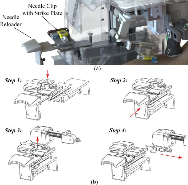
We implemented an automated needle handling system to limit practitioner contact with exposed sharps, in order to reduce the risk of accidental needle sticks and improve safety throughout the procedure. To achieve this, we fabricated a reloader mechanism consisting of linear ball bearing sliders and a spring-based push-to-open grab latch. First, the clinician manually loads the needle, with the attached clip containing the EM, onto the designated slot on the reloader [see Fig. 7(a)] with the cap still in place. The clinician then pushes the latch closed, aligning the cannula in the proper position and orientation for the robotic arm [see Fig. 7(b)].
Fig. 7.
(a) CAD rendering the needle reloader system. (b) Step-by-step protocol: Step 1: the clinician manually loads the needle into the tray; Step 2: the clinician closes the tray; Step 3: the manipulator grabs the needle via an electromagnetic mechanism; and Step 4: the manipulator translates to remove the cap and proceeds with the venipuncture.
When the manipulator is ready to grab the needle, it translates horizontally in the y-direction, engages the EM in the end-effector, and latches onto the needle via the strike plate (i.e., steel washer) embedded in the needle clip. Once inserted in the vein, the needle disengages from the robot by deactivating the EM, and the clinician completes the procedure (e.g., interchanging blood vials in the case of a blood draw).
V. Experiments
A. Manipulator Tracking Experiments
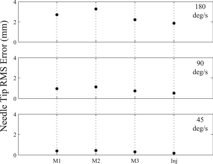
To first evaluate the control scheme for the robot arm, frequency-tracking experiments were performed for each joint independently using sine wave inputs. In these studies, sine wave frequencies were varied from 45–180 °/s to simulate the absolute minimum and maximum speed ranges the manipulator would encounter during a venipuncture procedure. The wave amplitude was maintained at 10° for each revolute joint and 5 mm for the injection system. Fig. 8 displays the results from these experiments, showing RMS errors at the needle tip. Frequency testing indicated that each joint was controllable and highly repeatable (mean standard deviation across all tests was 0.005 mm).
Fig. 8.
Average RMS error (n = 3) for each joint in the needle manipulator at high (180 °/s), mid (90 °/s), and low (45 °/s) frequency levels. M1 = motor 1; M2 = motor 2; M3 = motor 3; Inj = injection actuator.
B. Needle Positioning Testing
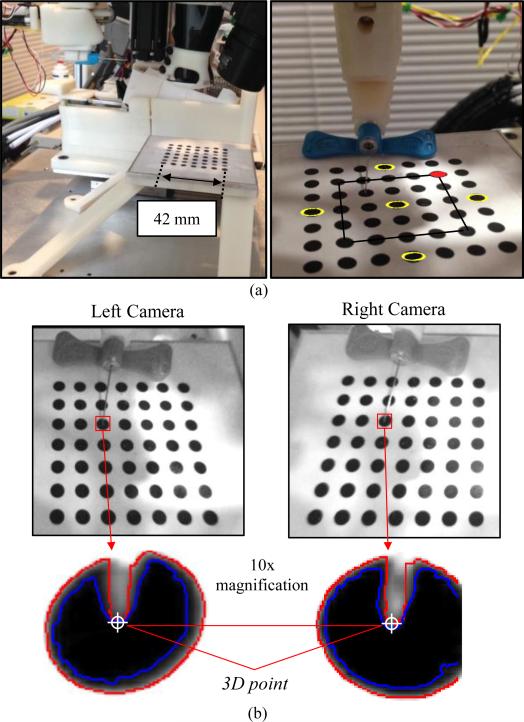
To test the positioning accuracy, precision, and operating workspace of the needle manipulator, we conducted studies in which we positioned the needle tip on the center of ø4 mm circles on a calibration grid. The circles were oriented on a flat plane in a 7 × 7 grid separated by 7 mm center-to-center. The grid structure was rigidly mounted to the base of the robot [see Fig. 9(a)]; hence, we could relate the coordinates of the circles with the robot coordinate frame by extracting the dimensions from the CAD model.
Fig. 9.
(a) Experimental setup of the needle positioning testing (left) and an image of the robot calibration grid (right). Yellow circles denote those used for repeatability testing; inner 5 × 5 grid outlined in black, indicates circles used for positioning studies; and red circle indicates plot origins in Fig. 10. (b) Stereo NIR images with the needle tip outlined in red, and 10× magnified images illustrating the region grow (blue) and edge detection (red) algorithms to segment the needle tip. Final needle tip selection was performed manually to ensure minimal errors. The 10× images have a pixel resolution of 0.1 mm.
In all experiments, the robot arm was initially set on the gantry; therefore, the needle was in-plane with the middle circles along the y-axis. For each trial, the experimental protocol included extracting the center of the circle (x, y, z) via the robot frame, then using this coordinate as the input into the inverse kinematic controls of the manipulator to set the required joint parameters to position the needle tip on the center of the circle. Finally, the desired circle center location extracted from the CAD model was compared to the actual needle tip position using the fixed cameras on the robot. Needle tip segmentation was achieved using a region grow formula with a Canny edge detector. To ensure minimal errors, we manually selected the needle tip in the post-processed images. Fig. 9(b) shows stereo NIR images of the needle tip positioned at the center of a test circle on the calibration grid, as well as the resulting needle tip segmentation from the region grow algorithm and edge detector.
To first test the repeatability of the needle manipulator, we ran 50 trials on the five yellow outlined circles labeled in Fig. 9(a) and compared the actual versus desired needle tip position. The average 3-D positioning error (mean ± standard deviation) was 0.81±0.02, 0.79±0.01, 0.94±0.02, 0.66±0.02, and 0.52±0.02 mm for the front, middle, back, left, and right circles, respectively. These circles were chosen to test the repeatability of the manipulator across the workspace area. Although the positioning errors were greater than expected, the low standard deviation values indicate that the serial arm is extremely repeatable.
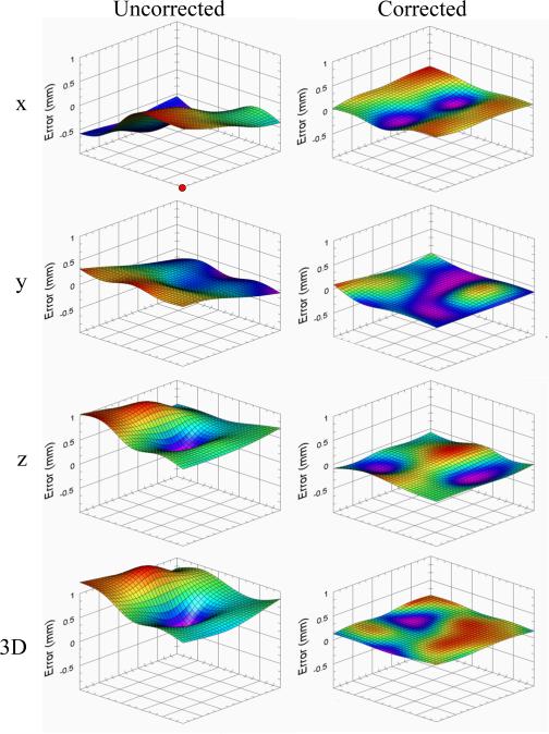
To further test the free-space positioning accuracy, the calibration grid was removed, and the needle tip was then placed at the coordinate of every circle within the inner 5 × 5 grid, as indicated by the black square outlined in Fig. 9(a). During the experiment, the height of the grid was varied over seven heights at vertical increments of 4 mm. This way, the accuracy of the robot was evaluated over 175 evenly spaced positions within a 28 × 28 × 24 mm work volume. By determining the exact offset of the manipulator at each grid point, and then interpolating (bicubic method) at every position in between, dense x, y, and z error correction maps were created at different heights. Fig. 10 displays the qualitative error maps at a z height of 78 mm, and Table III presents the quantitative results across the seven heights.
Fig. 10.
Needle tip positioning error maps in the uncorrected (left) and corrected (right) states for x, y, z, and 3-D at a 78-mm platform height. Bicubic interpolation was used to estimate errors between dots in the calibration grid. Significantly greater accuracy was observed after error compensation in x, y, z, and 3-D (p<0.001, two-sample t-test). Red circle in top left plot indicates the origin corresponding to the red circle in Fig. 9.
TABLE III.
Mean (N = 25) Needle Tip Positioning Errors; dx, dy, and dz Refer to the Needle Tip Error in the x, y, and z Dimensions,Respectively
| Before Error Compensation |
After Error Compensation |
|||||||
|---|---|---|---|---|---|---|---|---|
| Platform Height (mm) | dx (mm) | dy (mm) | dz (mm) | 3D (mm) | dx (mm) | dy (mm) | dz (mm) | 3D (mm) |
| 66 | 0.332 | 2.80 | 0.709 | 2.95 | 0.0780 | 0.0610 | 0.1728 | 0.211 |
| 70 | 0.283 | 1.745 | 0.488 | 1.871 | 0.0990 | 0.1601 | 0.0980 | 0.237 |
| 74 | 0.362 | 1.115 | 0.607 | 1.405 | 0.0840 | 0.0870 | 0.1214 | 0.1974 |
| 78 (ref) | 0.722 | 0.1099 | 0.583 | 0.949 | 0.0850 | 0.0850 | 0.0770 | 0.1592 |
| 82 | 0.351 | 0.952 | 0.549 | 1.236 | 0.0900 | 0.1075 | 0.1167 | 0.207 |
| 86 | 0.284 | 1.969 | 0.698 | 2.17 | 0.0930 | 0.1398 | 0.1234 | 0.226 |
| 90 | 0.326 | 2.01 | 0.641 | 2.19 | 0.1446 | 0.0980 | 0.1156 | 0.224 |
| Avg | 0.380 | 1.529 | 0.611 | 1.824 | 0.0960 | 0.1054 | 0.1178 | 0.201 |
Because of the high repeatability in the serial arm, we were able to input these error maps into our motor control algorithms to compensate for the subtle positioning inaccuracies. As shown in Fig. 10 and Table III, the robot demonstrated significantly reduced error after repeating the workspace accuracy experiments following error correction (3-D: 0.201 mm) compared with before (3-D: 1.824 mm). Overall, the results indicate that the manipulator is able to position the needle at a desired location both with high accuracy (mean positioning error: 0.21 mm) and precision (standard deviation: 0.02 mm) over the 3-D workspace of a typical venipuncture procedure.
The positioning errors observed in the manipulator may have stemmed from several sources. Namely, the needle tip extraction method used to determine the actual needle tip location had an accuracy of 0.1 mm due to the resolution in our NIR images (1 mm in x and y, 2 mm in z). In the future, we will design a clip with one calibration circle that can attach to the end effector via the EM. This will allow us to match the desired versus actual circle center location, and thus improve our robot calibration process, because segmenting a circle is much easier than segmenting the needle tip. Additionally, errors may have also stemmed from subtle inaccuracies in the fabrication and machining of our robotic components.
C. Phantom Cannulation Testing
Finally, we evaluated the image guided needle positioning accuracy of the venipuncture robot on a skin-mimicking phantom model embedded with surrogate veins. The phantom, which measured 80 × 50 × 10 mm, was fabricated out of gelatin (12 g/100 ml) to provide an elastic skin-like matrix. The surrogate veins consisted of silicone tubing (Silastic silicone elastomer tubing, Dow-Corning) of two diameters (3.2 and 1.8 mm). The elastic modulus of the tubing (9.5 kPa) closely matched that of typical adult peripheral veins (7–10 kPa). Blood-mimicking fluid (black India ink, diluted to 0.45 ml/100 ml to match the absorption coefficient of hemoglobin at 940 nm) was introduced into each vein prior to the experiment.
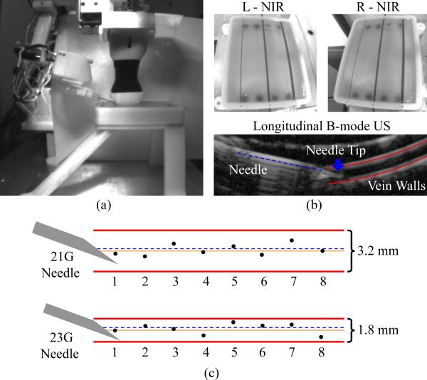
Fig. 11(a) illustrates the experimental setup, with the phantom model contained in a 3-D printed enclosure in which all veins lay 2 mm beneath the surface of the gelatin matrix. In total, 16 phantom vein cannulation trials were performed—eight for each vein diameter. The study evaluated the complete device workflow, including the coarse-fine stereo NIR and longitudinal US imaging approach [see Fig. 11(b)] as well as the 3-DOF gantry and 4-DOF manipulator controls. Briefly, the device imaged and segmented the phantom veins using 3-D NIR imaging and tracked the center of the selected vein using the US system. The robot then inserted the cannula bevel-up at 15° under US image guidance until the needle tip reached the center of the vein. Between each trial, the needle was retracted, the robot was homed, and then, the cannulation was repeated after shifting the cannulation site 10 mm along the length of the vein. After the study, the recorded US images were manually segmented and analyzed. The center of the vein was determined as the equidistant point between the upper and lower vessel walls (see Fig. 11(b), lower). The final needle insertion position was determined as the center of the cannula opening at the bevel tip.
Fig. 11.
(a) Experimental setup for phantom cannulation testing. (b) Left and right NIR images of an in vitro tissue phantom (top), and longitudinal US image during a needle insertion on the ø1.8-mm vein (bottom). (c) Results from the cannulation study—orange solid line refers to the desired vein center and black dots indicate the actual location of the needle (at the center of the cannula opening) for each trial. The dashed blue line indicates the average position of the needle within the vein over the eight trials.
Cannulation results are presented in Fig. 11(c). The RMS errors were 0.3±0.2 mm and 0.4±0.2 mm for the ø3.2- and ø1.8-mm veins, respectively. In all 16 trials, the robot was able to successfully cannulate the vein target on the first insertion attempt. In each of the eight trials on the 3.2-mm vein, the final needle tip position was closer to the vein center than to either vein wall, while this was true in six of the eight trials on the ø1.8-mm vein.
VI. Conclusion and Future Work
In this paper, we have presented the design and evaluation of a 7-DOF image-guided robotic system for automated venipuncture. The results of the tracking, positioning, and phantom cannulation experiments provide evidence that the robot has the accuracy needed to cannulate peripheral veins with high rates of success. Future accuracy studies will incorporate a calibration grid that covers the full, non-rectangular workspace of the manipulator (see Fig. 5) and, furthermore, will test the manipulator over a range of controlled insertion angles. Meanwhile, more realistic in vitro phantom models will be designed to simulate the optical, acoustic, and mechanical properties of adult and pediatric forearm veins. Finally, in vivo studies will be conducted in small animal models to assess the cannulation accuracy, sample collection success rate, completion time, and safety of the device.
Supplementary Material
Acknowledgment
The authors would like to thank the reviewers for insightful comments and suggestions.
This work was supported by an NI Medical Device Industrial Innovation Grant. The work of M. Balter was supported by an NSF Graduate Research Fellowship (DGE-0937373). The work of A. Chen was supported by the NIH/NIGMS Rutgers Biotechnology Training Program (T32 GM008339), and an NIH F31 Predoctoral Fellowship (EB018191).
Biographies
 Max L. Balter (M'14) received the B.S. degree in mechanical engineering from Union College, Schenectady, NY, USA, in 2012. He is currently working toward the Ph.D. degree in biomedical engineering with Rutgers University, Piscataway, NJ, USA, where he is an NSF Graduate Research Fellow.
He is also the Lead Mechanical Engineer with VascuLogic, LLC, Piscataway, NJ, USA. His research interests include mechanical design, mechatronics, medical robotics, image processing, and computational modeling.
 Alvin I. Chen (M'14) received the B.S. degree in biomedical engineering from Rutgers University, Piscataway, NJ, USA, in 2010, where he is currently working toward the Ph.D. degree in biomedical engineering as an NIH Predoctoral Fellow.
He is also the Lead Software Engineer with Vascu-Logic, LLC, Piscataway, NJ, USA. His research interests include image analysis, computer vision, machine learning, and robotics.
 Timothy J. Maguire received the B.S. degree in chemical engineering and Ph.D. degree in biomedical engineering from Rutgers University, Piscataway, NJ, USA, in 2001 and 2006, respectively.
He has published more than 20 peer-reviewed research papers and holds eight issued or pending patents in the biotechnology field. He is currently the CEO of VascuLogic, LLC, Piscataway, NJ, USA, as well as the Director of Business Development for the Center for Innovative Ventures of Emerging Technologies, Rutgers University.
 Martin L. Yarmush received the M.D. degree from Yale University, New Haven, CT, USA. He did Ph.D. research with The Rockefeller University (biophysical chemistry) and Massachusetts Institute of Technology (chemical engineering).
He is widely recognized for numerous contributions to the fields of bioengineering, biotechnology, and medical devices through more than 400 refereed papers and 40 patents and applications. He is currently the Paul and Mary Monroe Chair and Distinguished Professor of biomedical engineering with Rutgers University, Piscataway, NJ, USA, the Director for the Center for Innovative Ventures of Emerging Technologies, Rutgers University, and the Director for the Center for Engineering in Medicine, Massachusetts General Hospital, Boston, MA, USA.
Footnotes
This paper has supplementary downloadable material available at http://ieeexplore.ieee.org.
This paper was recommended for publication by Associate Editor J. Abbott and Editor B. J. Nelson upon evaluation of the reviewers’ comments.
Contributor Information
Max L. Balter, Department of Biomedical Engineering, Rutgers University, Piscataway, NJ 08854 USA, and also with VascuLogic, LLC, Piscataway, NJ 08854 USA (balterm53@gmail.com)..
Alvin I. Chen, Department of Biomedical Engineering, Rutgers University, Piscataway, NJ 08854 USA, and also with VascuLogic, LLC, Piscataway, NJ 08854 USA (alv6688@gmail.com)..
Timothy J. Maguire, Department of Biomedical Engineering, Rutgers University, Piscataway, NJ 08854 USA, and also with VascuLogic, LLC, Piscataway, NJ 08854 USA (tim.maguire25@gmail.com).
Martin L. Yarmush, Department of Biomedical Engineering, Rutgers University, Piscataway, NJ 08854 USA, and also with Massachusetts General Hospital, Boston, MA 02108 USA (yarmush@rci.rutgers.edu).
References
- 1.Ogden-Grable H, Gill GW. Phlebotomy puncture juncture preventing phlebotomy errors: Potential for harming your patients. Lab Med. 2005;36(7):430–433. [Google Scholar]
- 2.Walsh G. Difficult peripheral venous access: Recognizing and managing the patient at risk. J. Assoc. Vascular Access. 2008;13(4):198–203. [Google Scholar]
- 3.Campbell J. Intravenous cannulation: Potential complications. Professional Nurse (London, England) 1997 May;12(8 Suppl):S10–3. [PubMed] [Google Scholar]
- 4.Zaidi MA, Beshyah SA, Griffith R. Needle stick injuries - an overview of the size of the problem, prevention and management. 2010 [Google Scholar]
- 5.Porta C, Handelman E, McGovern P. Needlestick injuries among health care workers: A literature review. AAOHN J. 1999;47:237–244. [PubMed] [Google Scholar]
- 6.31-9097 Phlebotomists. U.S. Bureau of Labor Statistics; Washington, DC, USA: 2012. [Google Scholar]
- 7.Maecken T, Grau T. Ultrasound imaging in vascular access. Critical Care Med. 2007 May;35(5 Suppl):S178–85. doi: 10.1097/01.CCM.0000260629.86351.A5. [DOI] [PubMed] [Google Scholar]
- 8.Katsogridakis Y, Seshadri R, Sullivan C, Waltzman ML. Veinlite transillumination in the pediatric emergency department: A therapeutic interventional trial. Pediatric Emergency Care. 2008;24(2):83–88. doi: 10.1097/PEC.0b013e318163db5f. [DOI] [PubMed] [Google Scholar]
- 9.Perry AM, Caviness AC, Hsu DC. Efficacy of a near-infrared light device in pediatric intravenous cannulation: A randomized controlled trial. Pediatric Emergency Care. 2011;27(1):5–10. doi: 10.1097/PEC.0b013e3182037caf. [DOI] [PubMed] [Google Scholar]
- 10.Juric S, Flis V, Debevc M, Holzinger A, Zalik B. Towards a low-cost mobile subcutaneous vein detection solution using near-infrared spectroscopy. Sci. World J. 2014 Jan;2014:1–15. doi: 10.1155/2014/365902. [DOI] [PMC free article] [PubMed] [Google Scholar]
- 11.Graaff JC, Cuper NJ, Mungra RA, Vlaardingerbroek K, Numan SC, Kalkman CJ. Near-infrared light to aid peripheral intravenous cannulation in children: A cluster randomised clinical trial of three devices. Anaesthesia. 2013;68(8):835–845. doi: 10.1111/anae.12294. [DOI] [PubMed] [Google Scholar]
- 12.Beasley RA. Medical robots: Current systems and research directions. J. Robot. 2012;2012:401613. [Google Scholar]
- 13.Stoianovici D, Song D, Petrisor D, Ursu D, Mazilu D, Schar MMM, Patriciu A. MRI stealth robot for prostate interventions. Minimally Invasive Therapy Allied Technol. 2007;16(4):241–248. doi: 10.1080/13645700701520735. [DOI] [PMC free article] [PubMed] [Google Scholar]
- 14.Shoham M, Burman M, Zehavi EE, Joskowicz L, Batkilin E, Kunicher Y. Bone-mounted miniature robot for surgical procedures: Concept and clinical applications. IEEE Trans. Robot. Autom. 2003 Oct.19(5):893–901. [Google Scholar]
- 15.Glauser D, Fankhauser H, Epitaux M, Hefti JL, Jaccottet A. Neurosurgical robot minerva: First results and current developments. J. Image Guided Surgery. 1995 Jan;1(5):266–72. doi: 10.1002/(SICI)1522-712X(1995)1:5<266::AID-IGS2>3.0.CO;2-8. [DOI] [PubMed] [Google Scholar]
- 16.Stoianovici D, Cleary K, Patriciu A, Mazilu D, Stanimir A, Craciunoiu N, Watson V, Kavoussi L. Acubot: A robot for radiological interventions. IEEE Trans. Robot. Autom. 2003 Oct.19(5):927–930. [Google Scholar]
- 17.Bassan HS, Patel RV, Moallem M. A novel manipulator for percutaneous needle insertion: Design and experimentation. IEEE/ASME Trans. Mechatronics. 2009 Dec.14(6):746–761. [Google Scholar]
- 18.Boer TD, Steinbuch M, Neerken S, Kharin A. Laboratory study on needle–tissue interaction: Towards the development of an instrument for automatic venipuncture. J. Mech. Med. Biol. 2007;7(3):325–335. [Google Scholar]
- 19.Zivanovic A, Davies B. Proc. Med. Image Comput. Comput.-Assisted Intervention. Berlin, Germany: 2001. The development of a haptic robot to take blood samples from the forearm; pp. 614–620. [Google Scholar]
- 20.Perry TS. Profile veebot—Drawing blood faster and more safely than a human can. IEEE Spectrum. 2013 Aug.50(8):23–23. [Google Scholar]
- 21.Chen A, Nikitczuk K, Nikitczuk J, Maguire T, Yarmush ML. Portable robot for autonomous venipuncture using 3D near infrared image guidance. Technology. 2013;01(01):1–16. doi: 10.1142/S2339547813500064. [DOI] [PMC free article] [PubMed] [Google Scholar]
- 22.Kuensting LL, DeBoer S, Holleran R, Shultz BL, Steinmann R, Venella J. Difficult venous access in children: Taking control. J. Emergency Nursing. 2009 Sep;35(5):419–424. doi: 10.1016/j.jen.2009.01.014. [DOI] [PubMed] [Google Scholar]
- 23.Bashkatov AN, Genina EA, Kochubey VI, Tuchin VV. Optical properties of human skin, subcutaneous and mucous tissues in the wavelength range from 400 to 2000 nm. J. Phys. D, Appl. Phys. 2005;38(15):2543–2555. [Google Scholar]
- 24.Bouguet JY. Camera calibration toolbox for Matlab. 2013 [Google Scholar]
- 25.Heikkila J. Geometric camera calibration using circular control points. IEEE Trans. Pattern Anal. Mach. Intell. 2000 Oct.22(10):1066–1077. [Google Scholar]
- 26.Berkhoff AP, Huisman HJ, Thijssen JM, Jacobs EMGP, Homan RJF. Fast scan conversion algorithms for displaying ultrasound sector images. Ultrasonic Imag. 1994;16(2):87–108. doi: 10.1177/016173469401600203. [DOI] [PubMed] [Google Scholar]
- 27.Lasso A, Heffter T, Rankin A, Pinter C, Ungi T, Fichtinger G. Plus: Open-source toolkit for ultrasound-guided intervention systems. IEEE Trans. Biomed. Eng. 2014 Oct.61(10):2527–2537. doi: 10.1109/TBME.2014.2322864. [DOI] [PMC free article] [PubMed] [Google Scholar]
- 28.Frangi AF, Wiro JN, Vincken KL, Viergever MA. Proc. Med. Image Comput. Comput.-Assisted Intervention. Berlin, Germany: 1998. Multiscale vessel enhancement filtering; pp. 130–137. [Google Scholar]
- 29.Adams R, Bischof L. Seeded region growing. IEEE Trans. Pattern Anal. Mach. Intell. 1994 Jun.16(6):641–647. [Google Scholar]
- 30.Denavit RSHJ. A kinematic notation for lower-pair mechanisms based on matrices. ASME J. Appl. Mechan. 1955;22:215–221. [Google Scholar]
Associated Data
This section collects any data citations, data availability statements, or supplementary materials included in this article.


