Abstract
Recent advances in mammalian, insect, and stem cell cultivation and scale-up have created tremendous opportunities for new therapeutics and personalized medicine innovations. However, translating these advances into therapeutic applications will require in vitro systems that allow for robust, flexible, and cost effective bioreactor systems. There are several bioreactor systems currently utilized in research and commercial settings; however, many of these systems are not optimal for establishing, expanding, and monitoring the growth of different cell types. The culture parameters most challenging to control in these systems include, minimizing hydrodynamic shear, preventing nutrient gradient formation, establishing uniform culture medium aeration, preventing microbial contamination, and monitoring and adjusting culture conditions in real-time. Using a pneumatic single-use bioreactor system, we demonstrate the assembly and operation of this novel bioreactor for mammalian cells grown on micro-carriers. This bioreactor system eliminates many of the challenges associated with currently available systems by minimizing hydrodynamic shear and nutrient gradient formation, and allowing for uniform culture medium aeration. Moreover, the bioreactor’s software allows for remote real-time monitoring and adjusting of the bioreactor run parameters. This bioreactor system also has tremendous potential for scale-up of adherent and suspension mammalian cells for production of a variety therapeutic proteins, monoclonal antibodies, stem cells, biosimilars, and vaccines.
Keywords: Bioengineering, Issue 92, single-use bioreactor, cell culture, mammalian cell culture, pneumatic wheel, upstream bioprocessing, Air-Wheel bioreactor
Introduction
Mammalian cells lines can be classified into one of three categories based on their growth characteristics: cells that grow in suspension, cells that grow as aggregates, and cells that grow anchored to a substrate. Although the air-wheel bioreactor demonstrated in this video is able to grow all three types of cells, this video will demonstrate use of the bioreactor to grow anchorage dependent cells on micro-carriers. Anchorage dependent mammalian cells can be grown for the purpose of producing more cells — where the cells themselves are the product. For example, human bone marrow derived mesenchymal stem cells are currently being cultivated with the purpose of harvesting the cells and injecting them into diseased tissue. The pneumatic bioreactor demonstrated in this video has proven suitable for the production of such mesenchymal stem cells for this application (Serra et al., personal communication, 2013).
Anchorage dependent mammalian cells are typically grown small scale in 2D culture vessels such as cell culture plates, cell culture flasks, or roller bottles, where they adhere to a specially treated growth surface1. When more cells are desired, the plates or flasks can be expanded by using more or larger vessels. However, for more cost-effective cultivation of large quantities of anchorage dependent cells, increasing the surface area for cell attachment can be accomplished by using small solid beads called micro-carriers. Depending on the attachment characteristics of the cell, several different types of micro-carriers are commercially available, such as dextran, peptide, or collagen coated. Micro-carriers have a large surface area to volume ratio providing a larger surface area for cell growth; and the micro-carriers can be maintained in suspension with agitation, which allows the cells to be cultivated to high densities in bioreactor systems2. Currently, the types of bioreactors where adherent cells are grown on micro-carriers include spinner flasks and stirred tank systems, which use axial impellers to maintain suspension of the cell coated micro-carriers.
Several factors are important to the successful cultivation of cells including oxygen tension, shear stress, surface matrix, and nutrient and metabolite concentrations. The use of bioreactors allows for real-time monitoring of the growth conditions and the potential to significantly lower production costs1. There are several common bioreactor designs for in vitro cell cultivation including, stirred suspension, rotating wall vessel, hollow-fiber, bag bioreactor on a rocker platform, and fluidized bed systems3. Many of these systems present unique problems for cell cultivation and scale –up, such as high cost, nutrient concentration gradients, hydrodynamic shear, cell aggregation, and difficulty in sampling, monitoring, and controlling cell scale-up.
Various adherent cell lines are used in the production of viruses, either in the production of viral vaccines or for the production of viral vectors for gene therapy applications. In this video, using the single use pneumatic (Air-Wheel) bioreactor system, we demonstrate the culture of human lung carcinoma cells (A549) cells on micro-carriers for production of an oncolytic adenovirus. The pneumatic bioreactor design uses a vertical agitation wheel that is powered by the buoyancy of gas sparged into the bottom of the bioreactor. This gentle stirring method limits hydrodynamic shear forces, but still ensures optimal medium and cell mixing4. As compared to the stirred tank reactor, the pneumatic reactor has low wall shear stress even with high volume Air-Wheel bioreactor systems (Figure 1). In contrast to stirred tank bioreactors, the vertical impeller of this single use reactor is turned by a stream of gas bubbles within the vessel, which allows for gentle and uniform medium mixing (Figure 2).
Protocol
1. Login
Power up the Bioreactor. Click anywhere to open the login page. Select user name and enter password and click “Login”.
2. Calibration
Calibrate pH sensor (2 point prior to autoclaving).
Inspect pH sensor and confirm sensor tip is filled with electrolyte solution. Prepare two beakers with pH calibration solutions (electrolyte) pH 4 and pH 7 and have available a wash bottle with distilled water.
Connect the pH cable to the pH sensor. Navigate to the “Actions” tab on the Hello interface and click “calibrate”. Enter buffer temperature in the Calibration Solution Temp field.
Place pH sensor in buffer 1 (pH 4) and enter value in the “zero” field. Wait for the graph to stabilize and the click the “calibrate 1” button. Rinse the pH sensor with distilled water.
Place sensor in buffer 2 (pH 7). Enter buffer 2 value in the “span” field. Wait for graph to stabilize and click calibrate 2 button.
Click “Save” then click “Close”.
Calibrate the Dissolved Oxygen (DO) sensor.
Ensure the DO sensor has been polarized by being connected to the system for several hours. Navigate to the “Actions” tab on the Hello interface and click calibrate. Click the “DO A” button.
Disconnect the DO sensor and enter 0 in the “zero” field. Wait for the graph to stabilize and the click the “Calibrate 1” button.
Reconnect the DO sensor and enter 100 in the “Span” field. Wait for the graph to stabilize and the click the “Calibrate 2” button.
Click “Save” then click “close”.
3. Autoclave and Install Sensors and Reagent Vessels
After calibration, place sensors and thermal well in autoclave pouches and autoclave for 30 min at 121 °C, 15 psi.
Sanitize autoclave pouches with 70% Isopropyl Alcohol (IPA) and transfer pouches to biological safety cabinet (BSC). Remove outer packaging of vessel.
Sanitize inner packaging with 70% IPA and transfer vessel to biological safety cabinet (BSC). Remove inner packaging and inspect the vessel and tubing for damage inflicted during shipping.
Install the pH and DO sensors in the two front ports. Install the thermal well to the left back port. Open the sensor cap.
Guide the sensor through the sensor port. Thread the sensor tightly into the port.
Transfer vessel out of BSC.
Hang the DO and pH sensor cables outside the vessel sleeve and check that nothing is in the sleeve. Slide the vessel into the sleeve, feet first.
Carefully fit the temperature sensor into the vessel thermal well. Ensure that the bottom of the vessel rests against the heaters.
Remove the tubing sets from their bags. Match color coding on the tubing to the corresponding connectors and pumps on the bioreactor control unit.
Install the main gas line by pressing the connector into its gas outlet. Install the micro gas line by twisting the connector clockwise into the gas outlet. Install the exhaust filter tubing:
Open the filter oven. Secure the exhaust filter on the U-channel so its tubing goes through the two hooks to the filter and out of the oven.
Install the tubing by condenser bag in the tubing holder. Close the door.
Route addition lines A and B, both media lines, and the harvest line behind the DO sensor and onto the bench next to the bioreactor control unit.
Connect the cables to the DO and pH sensors.
4. Adding Medium and Micro-carriers
Navigate to the “actions” tab and click “Control Pumps” on the computer interface.
Form a sterile connection between an unused medium addition line (1 orange band) and the medium bottle/bag source by welding the tubing or using Luer fittings.
Click the slider to turn on the media pump on. Click the slider to turn the media pump off after addition desired amount of medium.
Place microcarrier beads in Ca2+, Mg2+ free PBS for 3 hr at RT.
Wash beads several times with Ca2+, Mg2+ free PBS.
Autoclave for 15 min at 115 °C, 15 psi. NOTE: Add 3 g/L (dry weight) in this experiment.
Pump in micro-carriers that have been hydrated, washed and autoclaved into the reactor in the same manner the medium was added in step 4.1.
5. Equilibration and One-point DO Calibration
Set the controllers to Auto and enter the desired setpoints. Here, use Agitation Set Point (SP) = 15 rpm, Temperature SP = 37.0 °C, pH = 7.2, DO = 100%. Wait for the parameters to equilibrate.
Confirm sensor is fully polarized. Confirm DO present value has stabilized.
Navigate to the “Actions” tab and click “calibrate”. Click “DO A”, click “One-point”.
Enter ‘100’ in the “Span” field. Click the “Calibrate 1” button, click “Save” and click “close”:
6. Starting a Run
Navigate to the Actions tab. Click “Batch.” Use the on-screen keyboard or an external keyboard to enter a batch name 16 characters or less.
Click the on-screen keyboard’s “Hide” button. Click the “Start batch” confirm by clicking “Start” in the overlay.
7. Inoculate with Cells
Form a sterile connection between an unused medium addition line (1 orange band) and the cell bottle/bag source by welding the tubing or using the Luer fittings.
Install the silicone section of the tubing in the media pump so the arrow points toward the tubing between the pump and vessel.
Check tubing clamp is open and its branched tubing clamp is closed. Click the slider to turn the media pump on and click to “Off” after adding cells.
Navigate to the “Actions” tab and click “Control Pumps”.
8. Sampling
After inoculating and as frequently as desired to monitor the culture, draw a sample from the culture in the following manner:
Navigate to the “actions” tab and click “take sample”. Place the sampling tubing in the sampling pump and manipulate the sampling stopcock according to the on-screen instructions.
Perform at least a daily microscopic observation and cell count on these samples.
When the cells have reached the desired density, in this case 1.2 x 10⁶ cells/ml, infect the cells with the addition of a virus inoculum.
Aseptically add the inoculum to a 20 ml syringe, and connect the syringe to one of the spare addition ports on the reactor. Introduce the inoculum to the reactor by pressing on the syringe plunger.
Continue sampling and analyzing the culture for the adenovirus intracellular particle concentration.
Representative Results
In Figure 3, the parameters for initiation of the bioreactor run are shown. This figure shows the screen prior to setting the parameters of temperature, dissolved oxygen, pH and agitation. Once the parameters are set, the run parameters are continuously monitored and adjustments can be made to maintain the required conditions. The software produces a continuous readout that allows for easy identification of problems. In this experiment using 2.5 L of DMEM containing 10% FBS, 250 ppm of SAFC Anti-foam C, 2 mm L-glutamine and 3 g/L of micro-carriers, the system is stabilized so the percent oxygen is 50%, the temperature is 37 °C, and the pH is 7.2. The reactor is inoculated with A549 cells at a concentration of 7 x 10⁴ cells/ml (or 10 cells/micro-carrier). The parameters chosen for this run resulted in the majority of the cells adhering to the micro-carriers within 2 hr (Figure 4). After 12 hr, the cells are demonstrating signs of flattening and spreading on the micro-carrier surface (Figure 5). By 24 hr, micro-carriers have a relatively even distribution of cells, with no micro-carriers without cells and no large clumps of cells on the micro-carriers (Figure 6). The percentage of micro-carrier colonization by A549 cells is 75% by 24 hr and 90% thereafter (Figure 7). The cells continued to grow exponentially to ~1 million cells/ml after 48 hr (Figure 8). After infection by a dose of oncolytic adenovirus (2 x 10⁸ virions/ml) at 50 hr, the density increased to 1.2 million cells/ml and then began to decrease as the lytic infection progressed. There was ~10,000 fold amplification of the viral inoculum.
In previous experiments, we have found that monitoring and adjusting gas flow is critical to maximizing cell growth (unpublished data). Rapidly growing cells can deplete the system of oxygen with the DO level dropping to zero. While the cells continued to grow, it was at a much slower rate. It is critical to monitor and adjust the oxygen flow to meet the cell demands during the logarithmic growth phase. Each run can be analyzed for optimal growth by comparing the pH, DO, and temperature with daily cell counts.
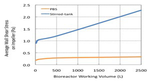 Figure 1.Fluid dynamics of the Pneumatic Bioreactor System (PBS) compared with a Stirrer tank bioreactor measuring wall shear forces at various reactor volumes.
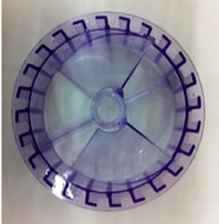 Figure 2.
Pneumatic Air-Wheel reactor impeller.
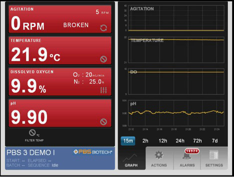 Figure 3.
Pneumatic Air Wheel software screen shot of parameters to initiate the bioreactor run.
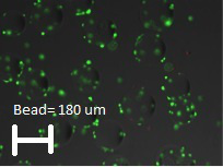 Figure 4.Micro-carrier colonization with A549 cells 2 hr post inoculation. (Average micro-carrier diameter ~180 µm.) Please click here to view a larger version of this figure.
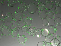 Figure 5.
12 hr after the initiation of the culture, the A549 cells are attaching, flattening, and spreading onto the micro-carriers.
Please click here to view a larger version of this figure.
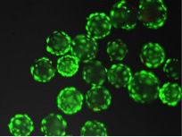 Figure 6.
Micro-carriers coated with cells after 24 hr in culture.
Please click here to view a larger version of this figure.
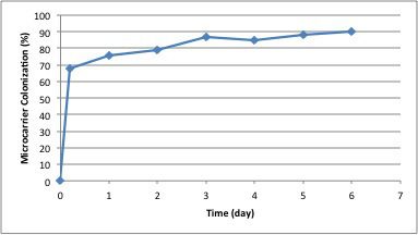 Figure 7. Percentage of micro-carrier colonization by A549 cells post inoculation.
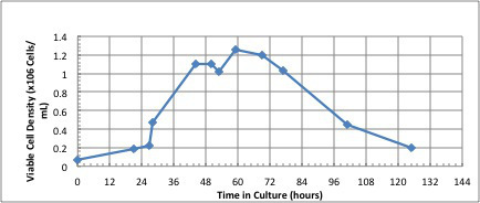 Figure 8.The number of viable A549 cells in culture pre and post infection with adenovirus. Note that the viral infection step occurred at 50 hr.
Discussion
This single-use bioreactor system is relatively simple to use and provides real-time analytics for reactor monitoring and analysis. It is extremely well suited for mammalian and insect cell culture with cell densities reaching over 30 million cells/ml. Besides A549 cells described in this report11, we have grown SF-9 insect cells in the bioreactor as well. The gentle mixing provided by the pneumatic air wheel reduces cell damage. Several steps are critical when setting up this reactor. First, proper calibration of the pH and DO sensors is important for optimal monitoring of the culture and for addition of reagents to adjust the pH or the oxygen in the system. Second, the reagent and seed bottles must be filled and the luer attachments made in a sterile environment such as a BSC. Once the reagent bottles are moved out of the sterile environment, the connections to the bioreactor feed lines must be made with care to avoid microbial contamination.
While this bioreactor system works well for mammalian and insect cell lines it is not designed for bacterial cultures. The system cannot provide the rapid mixing and oxygenation that is required for bacterial cells. Bacterial growth is best accomplished in a stirred tank bioreactor. As compared to other single use bioreactors for mammalian or insect cell culture, this system is easy to use, provides sufficient data for analysis of runs, and has similar or better cell growth than the other single use system we have evaluated.
The single use pneumatic bioreactor system has the potential to meet many of the research and clinical applications in the fields of biotherapeutics, vaccines, stem cells, and personalized medicine4. In addition, the flexibility of this system allows for Batch, Fed-batch, Perfusion, and Transfection based bioreactor applications5. Finally, single-use disposable bioreactor systems have the potential to meet the needs of large scale industrial production and to adhere to guidelines and recommendations of national and international regulatory agencies6-10.
Disclosures
Authors D. Giroux and Y. Hashimura are employees of PBS Biotech that produces reagents and instruments used in this article.
Acknowledgments
This project was support in part by Johns Hopkins University, Office of the Provost through the Gateway Science Initiative.
References
- Freshney RI. Culture of Animal Cells A Manual of Basic Techniques and Specialized Applications. 6th edition. Hoboken, NJ: John Wiley & Sons, Inc; 2010. [Google Scholar]
- Healthcare GE. Microcarrier Cell Culture Principles and Methods. GE Healthcare Data File 18-1140-62. 2005.
- Simaria AS, et al. Allogeneic cell therapy bioprocess economics and optimization Single-Use cell expansion Technologies. Biotechnol and Bioeng. 2014;111(1):69–83. doi: 10.1002/bit.25008. [DOI] [PMC free article] [PubMed] [Google Scholar]
- Lee B, Fang D, Croughan M, Carrondo M, Paik S-H. Characterization of novel pneumatic mixing for single-use bioreactor application. BMC Proc. 2011;5(S8):O12. doi: 10.1186/1753-6561-5-S8-O12. [DOI] [PMC free article] [PubMed] [Google Scholar]
- Eibl R, Eibl D. Disposable bioreactors in cell culture-based upstream processing. BioProcess Int. 2009;7(S1):18–23. [Google Scholar]
- Chaubard JF, et al. Disposable bioreactors for viral vaccine production challenges and opportunities. Biopharm Int Supp. 2010.
- Croughan MS, Hamel JF, Wang DIC. Hydrodynamic Effects on Animal Cells Grown in Microcarrier Cultures. Biotechnol and Bioeng. 2006;95(2):295–305. doi: 10.1002/bit.21158. [DOI] [PubMed] [Google Scholar]
- DePalma A. Single-use Equipment on Cusp of Industrialization. Genet Eng Biotechnol News. 2012;32(1) [Google Scholar]
- Baltz RH, Demain AL, Davies JE. Manual of Industrial Microbiology and Biotechnology. 3rd ed. Washington, DC: ASM Press; 2010. [Google Scholar]
- Applied Technical Bioreactors . Seminole (FL), USA: 2012. [Accessed 2012 11 27]. http://www.infors-ht.com/index.php/en/products/bioreactors/bench-top-bioreactors/minifors. [Google Scholar]
- Sousa MF, Giroux D, Clemente J, Lee B, Carrondo MJ, Alves PM. Impact of Bioreactor Design on the Performance of Microcarrier Cultures. 3rd ed. Scottsdale, Arizona: Cell Culture Engineering XIII; 2012. (Abstract). [Google Scholar]


