Abstract
This procedure describes a method for the fabrication of large-area and ultrathin free-standing polymer films. Typically, ultrathin films are prepared using either sacrificial layers, which may damage the film or affect its mechanical properties, or they are made on freshly cleaved mica, a substrate that is difficult to scale. Further, the size of ultrathin film is typically limited to a few square millimeters. In this method, we modify a surface with a polyelectrolyte that alters the strength of adhesion between polymer and deposition substrate. The polyelectrolyte can be shown to remain on the wafer using spectroscopy, and a treated wafer can be used to produce multiple films, indicating that at best minimal amounts of the polyelectrolyte are added to the film. The process has thus far been shown to be limited in scalability only by the size of the coating equipment, and is expected to be readily scalable to industrial processes. In this study, the protocol for making the solutions, preparing the deposition surface, and producing the films is described.
Keywords: Chemistry, Issue 100, Ultrathin films, free-standing, surface modification, polymers, large-area, fabrication
Introduction
Free-standing thin polymer films are used in a variety of applications including sensors, 1-3 MEMs, catalysis or filtration, 4 and tissue engineering. 5-8 They are also used for fundamental studies exploring the behavior of polymers under confinement. 9-13 A free-standing film is one that is supported on a non-continuous substrate such as an annular ring or hoop as opposed to a silicon wafer or glass slide. This work describes a simple, repeatable fabrication procedure for ultrathin free-standing polymer films that is suitable for large-area films or high-throughput production. It is compatible with a variety of different polymers, including poly(vinyl formal), polystyrene, and poly(methyl methacrylate). It can be used to fabricate free-standing films that are as large as 13-cm diameter or as thin as 10 nm.
The fabrication of free-standing polymers consists of three basic steps: 1) deposition of polymer film onto a traditional substrate such as a wafer or slide, 2) release or liftoff of the film from the substrate, and 3) capture of the resultant film onto a support. This paper details a procedure that we reported in an earlier study on various release methods. 14
Deposition can be achieved by any number of basic polymer thin film technologies such as spin-coating, vapor deposition, or dip-coating. In this work, we utilize standard spin-coating techniques.
The “lift off-float on” technique is the most common method for releasing an ultrathin film from its substrate. 15 In this technique, the film and substrate are immersed in a suitable solvent bath. The solvent swells the film and induces spontaneous delamination, releasing the film and allowing it to float to the top of the bath. The minimum film thickness that can be released using lift off-float on is determined by balancing the interfacial peeling energy with the swelling-induced strain energy: 16
 (1)
(1)
Where L is the film thickness, νf is the Poisson’s ratio of the film, E is the Young’s modulus of the film, ξ is the swelling ratio of the film, and γ is the interfacial energy of peeling. The typical way to bypass the limitation imposed by Equation (1) is to deposit a sacrificial interlayer between the film and the deposition substrate. 17-20 When this interlayer dissolves in a solvent bath, the film is released and can be captured on a support. A related method is the sacrificial overlayer method, which utilizes mechanical peeling of the film onto a sacrificial layer prior to dissolution. 21
The use of sacrificial materials has several chief drawbacks. First, the addition of an extra process material and step may require a compromise between optimal film fabrication conditions and sacrificial material processing conditions. Second, sacrificial materials may be difficult to deposit without affecting the mechanical properties or purity of the final free-standing film. Third, the process for depositing the sacrificial material must be optimized and monitored for quality as an operation in the overall free-standing film fabrication. 14
In this work, we describe a surface modification technique that decreases the interfacial peeling energy, enabling the lift off-float on technique to be used for ultrathin films. The deposition substrate is modified by assembling a self-limited, self-optimizing near-monolayer of the polycation polydiallyldiammonium chloride (PDAC). Because of the strength of the binding between the polycation and the substrate, this surface modification is robust to subsequent process steps. The self-limiting and self-optimizing nature of the near-monolayer formation requires practically zero optimization and is easily scalable to large areas.
Following removal, the film floats to the top of the solvent bath where it is captured on a hoop-like support. While not given much attention in the extant literature, in this work we will describe techniques for capturing large-area films on supports that reduce the probability of tearing or otherwise damaging the film.
Protocol
1. Solution Preparation
- Filter 60 g of ethyl lactate using a syringe and a 0.20 µm syringe filter. Add 0.3 g of polyvinyl formal to the ethyl lactate. Place the solution into the oven at 50 °C for 4 hr. Shake the vial gently to see if the polymer has dissolved completely.
- If the solution is cloudy or still shows optical inhomogeneities, return the vial to the oven for another 2 hr. This recipe is for a 0.5 wt% polymer solution, which is typically used for film thicknesses around 30 nm. Solutions with higher polymer weight content can be used for thicker films.
Prepare a PDAC solution by weighing 1.0 g of PDAC reagent in a 20 ml volumetric flask and filling the flask to the measuring line with deionized (DI) water. Swirl the solution gently before transferring it to a storage container.
2. Substrate Preparation
CAUTION. Pour 60 ml of concentrated sulfuric acid into a clean 250 ml beaker. Slowly add 20 ml of 30% hydrogen peroxide. Wait until fuming subsides, then swirl the solution gently. The solution and the beaker will become very hot and the mixture is corrosive.
- Place a 150 mm Petri dish onto the hot plate and pour the acid into the dish. Set the hot plate to 100 °C.
- Place a 4' silicon wafer into the acid with the polished side up. Gently push the wafer down in the middle with a pair of tweezers to make sure the entire surface is wetted. Leave the wafer in the acid for 30 min.
Remove the wafer from the acid with a pair of tweezers and rinse the front and back of the wafer thoroughly with DI water from a squirt bottle. The water should sheet off in a regular pattern. Dry the wafer in a clean bench.
Rinse a disposable 3 ml syringe and a 0.2 µm filter first with DI water and then with PDAC solution by drawing the liquid into the syringe, mounting the filter, and then pushing the liquid out through the filter.
Mount a cleaned wafer in the spin coater. Draw up 1.0-1.2 ml of PDAC solution into the syringe and dispense it though the filter onto the middle of the wafer. Spin at 4,000 rpm for 15 sec, then transfer the wafer to a hot plate (preheated to 50 °C) and let it sit for 30 sec.
Rinse the dried PDAC layer off with DI water and let the wafer dry in the clean bench.
3. Film Fabrication
Place a dry PDAC-treated wafer onto the spin coater.
Rinse a disposable 3 ml syringe and a 0.45 µm filter with the ethyl lactate solution using the procedure under 2.4).
Deposit 2.5 ml of the ethyl lactate solution through the filter with the syringe in the middle of the wafer and spin for 10 sec at 200 rpm, then for 3 sec at 1,700 rpm (dependent on desired film thickness). There should be a uniform liquid film on the wafer.
Let the film dry in the spin coater until it is visibly dry (typically 10-15 min), then place it on a hotplate (preheated to 50 °C) for 10 min.
- Dice the films into smaller squares for liftoff, typically 2 cm x 2 cm, but can be larger, depending on the size of the film holder used (3.5.1-3.5.2). Alternatively, make two scribes for delaminating a wafer-sized film (3.5.3). Note: Standard film holders are 19 x 19 mm, with a circular opening of 13 mm diameter in the middle. For wafer-sized films, use a wire hoop (e.g., stainless steel wire formed into a circle) with a diameter that is 1” smaller than the wafer. A circular opening is chosen because the films will typically absorb water during liftoff and swell. As the films dry on the holder, the water is removed and the film will shrink. A circular opening allows for an even distribution of stress.
- Place the wafer on a cutting template. Use a square template on which all edges are taller than the wafer to prevent the straight edge used to guide the blade during scribing from touching the wafer. Mark the edges in 2 cm intervals to guide the placement of the straight edge during dicing. Push the wafer against two edges to align it.
- Place a straight edge along two alignment marks, and draw a razor blade gently along the straight edge to scribe the film. Apply enough pressure to mark the film, but not too much to mark the wafer itself and produce particles. On thicker films, the cutting line will be clearly visible.
- To liftoff a film in one piece from the wafer, scribe the wafer edge with a razor blade. Between the two flats on the wafer, scribe a strip wide enough to clamp the wafer onto the rack-and-pinion.
- Fill a 190 x 100 mm culture dish with DI water. Clamp the wafer by the large flat to a rack-and-pinion mounted to a tilt stage and slowly lower it into the DI water. The film should separate from the wafer at the water line.
- Continue lowering the wafer at a rate that gives the film enough time to separate from the wafer, rather than pushing the lift-off interface below the water line. When the first row of squares has detached from the wafer and is floating on the surface, pause the lowering of the wafer. For a wafer-sized film, continue immersing the wafer until the film detaches completely.
- Immerse the head of the film holder into the water and move it underneath the film. Line up the handle edge of the hoop with one of the film edges and touch the hoop with the film. If successful, the film will stick to the hoop.
- For a wafer-size film, place the wire hoop underneath the scribed section, just a centimeter away from the edge. Make sure that the hoop is centered underneath the film before beginning the capture, maintaining some distance between film edge and hoop edge so that the film can wrap around the hoop and fold back on itself.
- Retract the hoop slowly from the water at an angle of 35°. Lift the film out of the water very slowly. Note: For films less than 20 nm thick, increase the angle after about half of the film has been pulled from the water to almost 90° (i.e., normal to the water surface) to avoid pulling the film through the holder. When changing the lift out angle, do so slowly to avoid pulling the film through the hoop.
- When the hoop is fully retracted, place it to the side to dry. Make sure the bottom of the hoop is free of drops before putting the hoop down, and use a curved surface (such as a wafer tray) to avoid creating a liquid seal between hoop and surface.
- If more scribed squares remain on the wafer, continue lowering the wafer into the water and repeat steps 3.6.1-3.6.4 above for remaining squares.
- Let the films dry O/N.
Representative Results
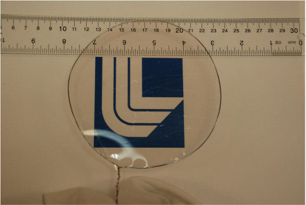
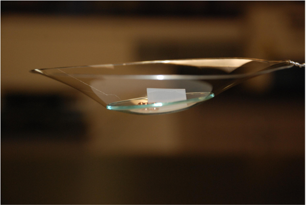
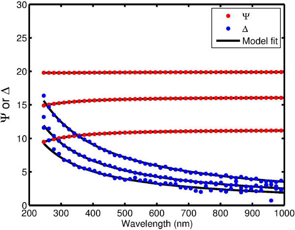
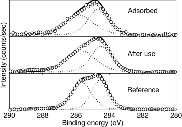
Figure 1 shows an example of a free-standing thin polymer film over a large area. This 55 nm thick polyvinyl formal film was fabricated using the procedure described here and is mounted on a 13-cm diameter steel hoop. The delamination occurs over large areas without introducing defects that lead to tearing of the film. Thus, the intrinsic strength of polyvinylformal can be exploited even for very thin films. Figure 2 shows a 22 nm thick free-standing film that is strong enough to be loaded with a watch glass and copper beads that weigh >3x10⁵ times the mass of the film itself. Spectroscopic ellipsometry can be used to confirm the thickness of the freestanding film. Figure 3 shows ellipsometric data for an 8.0 nm film. Silicon surfaces treated with PDAC can be used multiple times for film delamination; X-ray photoelectron spectroscopy (XPS) spectra in Figure 4 show that once deposited, the PDAC is robustly attached to the surface and is not removed during the lift-off procedure.
 Figure 1. A 55 nm thick polyvinyl formal film mounted on a 13 cm diameter steel hoop. Reprinted with permission from [14]. Copyright 2014 American Chemical Society. Please click here to view a larger version of this figure.
 Figure 2. A 22 nm thick, 13 cm diameter polyvinyl formal film loaded with a watch glass and copper beads. The total mass supported by the film is 10.5 g, while the mass of the film is estimated to be 0.336 mg. Please click here to view a larger version of this figure.
Discussion
The PDAC substrate treatment is based on self-limiting electrostatic interactions, meaning substrates of any size can be easily treated provided that they are negatively charged (e.g., silicon or glass). Figures 1-2 shows very large thin films (up to 13 cm in diameter) fabricated using this protocol, with the only change being the volume of reagents used. The ultimate achievable size appears to be limited only by the deposition and delamination equipment or the ultimate strength of the polymer used to fabricate the free-standing structure. While the former is clearly a practical issue, the latter is not a simple reflection of the intrinsic strength of the polymer. We have found that evaporation rate during spin coating and solvent selection — among other factors — can determine the film strength (data not shown). The critical step in producing defect-free films over large areas is the liftoff procedure described in 3.5-3.6 in the procedure and shown in the video. Careful delamination of the thin polymer film ensures that tears or holes do not form in the final free-standing assembly.
The swelling-induced delamination of thin polymer films from their deposition substrate is limited by the strain energy in the swollen film. This limitation results in a minimum thickness that can be delaminated as shown by Equation (1), a limitation which is usually circumvented by the use of sacrificial materials. In the protocol described here, no sacrificial materials are necessary because the interfacial peeling energy has been lowered by the PDAC-modification of the deposition substrate. Using this technique, we have delaminated polyvinyl formal films as thin as 8 nm, which is a factor of ten thinner than what is possible without the PDAC treatment. An ellipsometric measurement of a free-standing 8 nm film is shown in Figure 3.
 Figure 3. Spectroscopic ellipsometric data on a free-standing film collected at 65°, 70°, and 75° angles of incidence. For both ψ and δ, the curves for 65°, 70°, and 75° are arranged bottom to top. The model fits are generated using standard ellipsometric software using a Cauchy-void stack. The best-fit thickness for this film is 8.0 nm. Please click here to view a larger version of this figure.
The PDAC is effective because it decreases the interfacial peeling energy between the deposition substrate and the polymer. It is not a sacrificial layer, as evidenced by XPS spectra in Figure 4 showing its presence on the deposition substrate both before and after delamination. In fact, once treated with PDAC, a substrate can be utilized to deposit and delaminate films multiple times (at least up to ten) without any noticeable change in performance. The strong binding of the PDAC to the substrate is due to the strong electrostatic interaction between the positively charged polyelectrolyte and the negatively charged silicon substrate. 22,23
 Figure 4. X-ray photoelectron spectroscopy (XPS) data of wafers coated with PDAC before and after liftoff. The spectrum is largely unchanged, indicating that little if any PDAC is removed during the process. Open circles are data and the dashed lines are constituent peaks of C-N and C-C bonds. The solid black line is the enveloping curve. The reference curve is a thick (~20 nm) film of PDAC. Reprinted with permission from [14]. Copyright 2014 American Chemical Society. Please click here to view a larger version of this figure.
Despite its strong binding to the substrate, the PDAC binds only weakly to the overlying polymer thin film. The quaternary amine side chains of PDAC likely limit the interaction between the treated substrate and the polymer film to weak van der Waal’s forces, a mechanism which is applicable to a number of different polymer thin films. We have used the protocol described here to delaminate and fabricate free-standing thin films of polystsyrene (PS), polymethyl methacrylate (PMMA), and polyvinyl butyral. Recipes for preparing solutions and spin-coating parameters can be found for PS and PMMA. 24 We expect that this procedure can be generalized to other polymer systems as well, although it likely will not work for polyelectrolyte multilayers or partially acidic copolymers due to the potential for strong binding to the PDAC-treated substrate. The liftoff procedure must also be performed under pH and ionic conditions that will neither remove the PDAC from the substrate nor damage the polymer film to be delaminated.
This protocol represents a significant alternative to the use of sacrificial materials, which is the current state of the art for releasing ultrathin polymer films from their substrates. A separate optimization of the sacrificial material deposition is no longer required, and the self-limiting PDAC treatment is easily scalable to large areas as demonstrated here. We have found that films released using sacrificial underlayers display degraded strength characteristics. 14 This protocol will enable researchers to move one step closer to probing truly intrinsic mechanical properties of the free-standing polymers as well as applications in biomaterials or filtration requiring large-area thin films.
Disclosures
The authors have nothing to disclose.
Acknowledgments
This work performed under the auspices of the U.S. Department of Energy by Lawrence Livermore National Laboratory under contract DE-AC52-07NA27344.
References
- Cheng W, Campolongo MJ, Tan SJ, Luo D. Freestanding ultrathin nano-membranes via self-assembly. Nano Today. 2009;4:482–493. [Google Scholar]
- Greco F, et al. Ultra-thin conductive free-standing PEDOT/PSS nanofilms. Soft Matter. 2011;7:10642–10650. [Google Scholar]
- Matsui J, Mitsuishi M, Aoki A, Miyashita T. Molecular Optical Gating Devices Based on Polymer Nanosheets Assemblies. J. Am. Chem. Soc. 2004;126:3708–3709. doi: 10.1021/ja039871+. [DOI] [PubMed] [Google Scholar]
- Ulbricht M. Advanced functional polymer membranes. Polymer. 2006;47:2217–2262. [Google Scholar]
- Fujie T, et al. Robust Polysaccharide Nanosheets Integrated for Tissue-Defect Repair. Adv. Funct. Mater. 2009;19:2560–2568. [Google Scholar]
- Okamura Y, Kabata K, Kinoshita M, Saitoh D, Takeoka S. Free-Standing Biodegradable Poly(lactic acid) Nanosheet for Sealing Operations in Surgery. Adv. Mater. 2009;21:4388–4392. doi: 10.1002/adma.200901035. [DOI] [PubMed] [Google Scholar]
- Sreenivasan R, Bassett EK, Hoganson DM, Vacanti JP, Gleason KK. Ultra-thin gas permeable free-standing and composite membranes for microfluidic lung assist devices. Biomaterials. 2011;32:3883–3889. doi: 10.1016/j.biomaterials.2011.02.017. [DOI] [PubMed] [Google Scholar]
- Wan L-S, Liu Z-M, Xu Z-K. Surface engineering of macroporous polypropylene membranes. Soft Matter. 2009;5:1775–1785. [Google Scholar]
- Alcoutlabi M, McKenna GB. Effects of confinement on material behaviour at the nanometre size scale. Journal of Physics-Condensed Matter. 2005;17:R461–R524. [Google Scholar]
- Ellison CJ, Torkelson JM. The distribution of glass-transition temperatures in nanoscopically confined glass formers. Nature Materials. 2003;2:695–700. doi: 10.1038/nmat980. [DOI] [PubMed] [Google Scholar]
- Priestley RD, Ellison CJ, Broadbelt LJ, Torkelson JM. Structural relaxation of polymer glasses at surfaces, interfaces and in between. Science. 2005;309:456–459. doi: 10.1126/science.1112217. [DOI] [PubMed] [Google Scholar]
- Si L, Massa MV, Dalnoki-Veress K, Brown HR, Jones RAL. Chain entanglement in thin freestanding polymer films. Phys. Rev. Lett. 2005;94 doi: 10.1103/PhysRevLett.94.127801. [DOI] [PubMed] [Google Scholar]
- Torres JM, Stafford CM, Vogt BD. Elastic Modulus of Amorphous Polymer Thin Films: Relationship to the Glass Transition Temperature. Acs Nano. 2009;3:2677–2685. doi: 10.1021/nn9006847. [DOI] [PubMed] [Google Scholar]
- Baxamusa SH, et al. Enhanced Delamination of Ultrathin Free-Standing Polymer Films via Self-Limiting Surface Modification. Langmuir. 2014;30:5126–5132. doi: 10.1021/la5011665. [DOI] [PubMed] [Google Scholar]
- Buck ME, Lynn DM. Free-Standing and Reactive Thin Films Fabricated by Covalent Layer-by-Layer Assembly and Subsequent Lift-Off of Azlactone-Containing Polymer Multilayers. Langmuir. 2010;26:16134–16140. doi: 10.1021/la103009a. [DOI] [PMC free article] [PubMed] [Google Scholar]
- Freund LB, Suresh S. Thin Film Materials: Stress, Defect Formation and Surface Evolution. Cambridge University Press; 2003. [Google Scholar]
- Dubas ST, Farhat TR, Schlenoff JB. Multiple Membranes from “True” Polyelectrolyte Multilayers. J. Am. Chem. Soc. 2001;123:5368–5369. doi: 10.1021/ja015774+. [DOI] [PubMed] [Google Scholar]
- Linder V, Gates BD, Ryan D, Parviz BA, Whitesides GM. Water-soluble sacrificial layers for surface micromachining. Small. 2005;1:730–736. doi: 10.1002/smll.200400159. [DOI] [PubMed] [Google Scholar]
- Mamedov AA, Kotov NA. Free-Standing Layer-by-Layer Assembled Films of Magnetite Nanoparticles. Langmuir. 2000;16:5530–5533. [Google Scholar]
- Ono SS, Decher G. Preparation of Ultrathin Self-Standing Polyelectrolyte Multilayer Membranes at Physiological Conditions Using pH-Responsive Film Segments as Sacrificial Layers. Nano Lett. 2006;6:592–598. doi: 10.1021/nl0515504. [DOI] [PubMed] [Google Scholar]
- Stroock AD, Kane RS, Weck M, Metallo SJ, Whitesides GM. Synthesis of Free-Standing Quasi-Two-Dimensional Polymers. Langmuir. 2002;19:2466–2472. [Google Scholar]
- Kriz J, Dybal J, Kurkova D. Cooperativity in macromolecular interactions as a proximity effect: NMR and theoretical study of electrostatic coupling of weakly charged complementary polyions. J. Phys. Chem. B. 2003;107:12165–12174. [Google Scholar]
- Krogman KC, Zacharia NS, Schroeder S, Hammond PT. Automated Process for Improved Uniformity and Versatility of Layer-by-Layer Deposition. Langmuir. 2007;23:3137–3141. doi: 10.1021/la063085b. [DOI] [PubMed] [Google Scholar]
- Hall DB, Underhill P, Torkelson JM. Spin coating of thin and ultrathin polymer films. Polymer Engineering & Science. 1998;38:2039–2045. [Google Scholar]


