Abstract
Purpose:
This work is a preliminary study of a stationary cardiac SPECT system. The goal of this research is to propose a stationary cardiac SPECT system using segmented slant-hole collimators and to perform computer simulations to test the feasibility. Compared to the rotational SPECT, a stationary system has a benefit of acquiring temporally consistent projections. The most challenging issue in building a stationary system is to provide sufficient projection view-angles.
Methods:
A gate (geant4 application for tomographic emission) Monte Carlo model was developed to simulate a two-detector stationary cardiac SPECT that uses segmented slant-hole collimators. Each detector contains seven segmented slant-hole sections that slant to a common volume at the rotation center. Consequently, 14 view-angles over 180° were acquired without any gantry rotation. The NCAT phantom was used for data generation and a tailored maximum-likelihood expectation-maximization algorithm was used for image reconstruction. Effects of limited number of view-angles and data truncation were carefully evaluated in the paper.
Results:
Simulation results indicated that the proposed segmented slant-hole stationary cardiac SPECT system is able to acquire sufficient data for cardiac imaging without a loss of image quality, even when the uptakes in the liver and kidneys are high. Seven views are acquired simultaneously at each detector, leading to 5-fold sensitivity gain over the conventional dual-head system at the same total acquisition time, which in turn increases the signal-to-noise ratio by 19%. The segmented slant-hole SPECT system also showed a good performance in lesion detection. In our prototype system, a short hole-length was used to reduce the dead zone between neighboring collimator segments. The measured sensitivity gain is about 17-fold over the conventional dual-head system.
Conclusions:
The gate Monte Carlo simulations confirm the feasibility of the proposed stationary cardiac SPECT system with segmented slant-hole collimators. The proposed collimator consists of combined parallel and slant holes, and the image on the detector is not reduced in size.
Keywords: cardiac single photon emission computed tomography (SPECT), collimator, slant-hole, Monte Carlo simulation
1. INTRODUCTION
The growth of cardiovascular disease (CAD), which is a leading cause of death and morbidity worldwide, has created an urgent need for an efficient and noninvasive tool. Among current diagnostic methods, single photon emission computed tomography (SPECT), in particular SPECT myocardial perfusion imaging (MPI), remains the most important and efficient method for diagnosing coronary artery disease noninvasively.
In the past decade, several high-speed cardiac SPECT systems have been developed, e.g., D-SPECT (Spectrum Dynamics, Caesarea, Israel),1,2 Cardius 3 XPO (Digirad, Poway, CA),3 and CardiArc (CardiArc, Lubbock, TX).2,4 In comparison with the conventional SPECT system, dedicated cardiac SPECT permits fast acquisition due to high sensitivity and produces high quality images, facilitating the process of dynamic cardiac imaging. The usage of novel photon-collection and scanning geometries increases the detector efficiency significantly, but the detector motion or the slit motion in current cardiac systems leads to data inconsistencies between views, as do conventional rotational SPECT systems. A stationary system, however, can eliminate such motion and the associated data inconsistence.
To create a stationary system, the multipinhole technique, which is the state-of-the-art in small animal imaging, has been extended to human cardiac SPECT.5–10 With the main advantage being the pinhole magnification effect [Fig. 1(a)], it allows a high-sensitivity, high-resolution image to be obtained in small animal imaging.11 However, for human cardiac studies, the multipinhole system operates in minification mode, that is, the object is placed away from the pinhole and the images on the detector are smaller than the object [Fig. 1(b)], e.g., UC San Francisco and Western Cardiology Associate’s stationary multipinhole system7,8,12 and Discovery NM 530c (GE Healthcare, Haifa, Israel).9,10 The detection sensitivity is proportional to the image magnification factor. If the object is moved away from the pinhole, the image magnification factor becomes less than one, resulting in dramatic reduction of the detection sensitivity. When the pinhole magnification factor is less than one, the pinhole detection sensitivity becomes worse than that of a parallel-hole system.13 In this situation, the parallel-hole collimator outperforms the pinhole in detection sensitivity for human cardiac SPECT.
FIG. 1.
Pinhole collimation. (a) For small animal cardiac studies, the pinhole operates at magnification mode. (b) For human cardiac studies, the pinhole works in image reducing mode.
We therefore have investigated a novel dedicated stationary cardiac SPECT system with segmented slant-hole collimators, to provide greater detection sensitivity over the multipinhole cardiac SPECT system. The segmented slant-hole collimator, which is designed to fit existing dual-head SPECT cameras, includes seven subcollimators. During data acquisition, our novel system is completely stationary and 14 views in total are acquired simultaneously. Detailed designs and computer simulation results of the whole system are presented and compared with those of the conventional SPECT system.
2. DESIGN AND METHODS
2.A. Imaging configuration and modification
To take advantage of the existing dual-detector system and lower the cost of a stationary cardiac SPECT system, our strategy is to redesign the collimator for the conventional SPECT system to acquire more projection views for each detector position. In UC San Francisco’s stationary multipinhole system, a 3 × 3 configuration, as shown in Fig. 2(a), is used.7 Although the 3 × 3 configuration has nine pinholes in total, it only provides three view-angles in the horizontal (i.e., transaxial) direction and three view-angles in the vertical (i.e., axial) direction. Similarly, GE’s Discovery NM 530c (DNM), which has 19 pinholes configured in the 3 × 9 format, only provides nine independent views in the transaxial direction.10,14 The rows of pinholes in these systems are aligned in the axial direction, thus, the number of independent views in the transaxial direction are fewer than the number of pinholes. We noticed that a slight shift of the pinholes’ position can provide more view-angles in the horizontal plane, which is perpendicular to the rotation axis. In Fig. 2(b), we see that view-angles are staggered in the horizontal plane by shifting the top row of pinholes to the left and the bottom row of pinholes to the right, providing seven different view-angles in the horizontal plane. This modified approach increases the number of independent view-angles in the transaxial direction and is extended to the design of the segmented parallel-hole collimator [as seen in Fig. 2(c)].
FIG. 2.
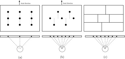
Image configuration and the view-angles in the horizontal direction. (a) UC San Francisco’s 3 × 3 pinhole configuration of their stationary system. (b) A revised, shifted 2-3-2 configuration. (c) The 2-3-2 configuration is used in the segmented parallel-hole collimator.
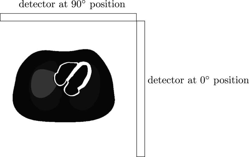
The projection data acquired from the anterior to left anterior oblique (LAO) aspects of the patient’s body have lower attenuation to the heart while the signal-to-noise ratio (SNR) is relatively high. Accordingly, in our design, two detectors are positioned in an L-configuration (Fig. 3), making it possible to acquire data by all segments over 180° from the LAO direction.
FIG. 3.
Two detectors are in an L-configuration.
2.B. Collimator designs
Our primary concern at this stage is the optimization of the collimator segment angles. The distance from the rotation center to the surface of the detector and the slant angle are chosen to minimize the overlap of the projections, maximize the acquisition angle (180°), and avoid out-of-boundary truncation of the projections in the region of interest (ROI). According to surveys of patient sizes and heart dimensions in a relatively large population,15–17 the size of the heart neither change very much between male and female nor between small patients and large patients. Therefore, it is possible to design a collimator that fits all patients. In our system, the central-field-of-view (CFOV) is set at 12 cm in diameter which is large enough to cover the left ventricle.
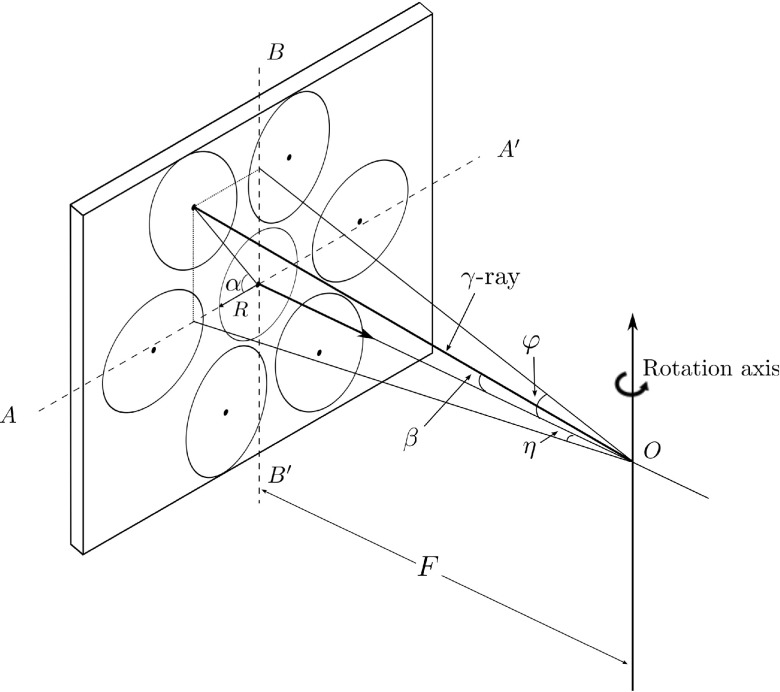
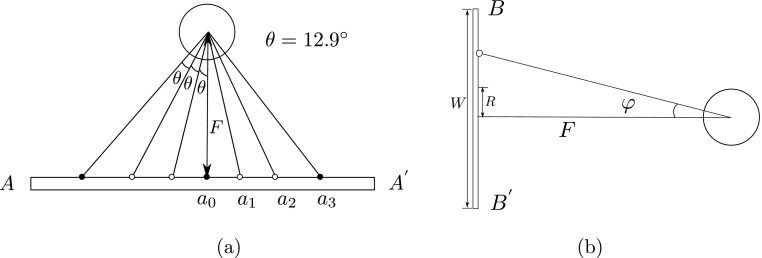
We assume the heart is contained in a sphere positioned in front of the CFOV and is seen by all subdetectors simultaneously. Its projection is a circle at the central subdetector and an ellipse at the outer position (see Fig. 4). Parameters are illustrated in Table I. Each detector should cover 90° to get the 180° full coverage by two detectors. There are seven subdetection regions in each detector, thus, the angular sampling interval θ = 90∘/7∘ = 12.9∘. In order to perform the L-configuration, the rotation radius F is chosen as half of the detector length, that is, F = 53.3/2 = 26.65 cm. Each slant angle η is determined according to Fig. 5(a). As seen in Figs. 5(b) and 4, the slant angle is also limited by the detector size and must satisfy
| (1) |
| (2) |
that is, φ ≤ 25.3761∘ and η ≤ 35.8396∘.
FIG. 4.
Definition of slant angles in segmented slant-hole collimator.
TABLE I.
Defined geometric parameters of segmented slant-beam collimator.
| Symbol | Description |
|---|---|
| α | Angle between the horizontal (i.e., transaxial) axis and the major axis of the ellipse |
| β | Angle between the detector norm and the γ-ray |
| φ | Slant angle of γ-ray in the horizontal (i.e., transaxial) direction, φ ∈ (−90∘, 90∘) |
| η | Slant angle of γ-ray in vertical (i.e., axial) direction, η ∈ (−90∘, 90∘) |
| L | Detector length, L = 53.3 cm |
| W | Detector width, W = 38.7 cm |
| R | Radius of the CFOV |
| F | Distance from the rotation center to the detector |
FIG. 5.
Calculate angles of the segmented slant-hole collimator. (a) seven views have an angular spacing of θ in the horizontal (i.e., transaxial) direction. (b) The slant angle φ in the vertical direction.
Applying the restrictions, the slant angles η are set as −35°, −25.7°, −12.9°, 0°, 12.9°, 25.7°, and 35°, respectively, and the corresponding angle φ are −6.1°, 22°, −24.5°, 0°, 24.5°, −22°, and 6.1°, respectively. The second detector is the same as the first detector, so we only need to design one detector and apply it to the other.
2.C. Using curved segment boundaries to fit images in the detector
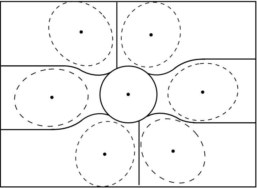
Unlike the parallel-hole collimator, the projections of the object are consequently elongated in the direction of slant. More detector space is therefore required in the direction of the slant for collimators at outer positions. The configuration in Fig. 2(c) is thus not very efficient and may cause out-of-boundary truncation in the vertical direction. Our modification is to replace some straight-line boundaries of the subcollimators [Fig. 2(c)] with curved boundaries as shown in Fig. 6. The central subdetector is round and has the most important tomographic information, so that there is no truncation to the heart in this region. The curved boundaries follow the projection boundaries of the sphere and are large enough to cover the whole heart. Realization of curved segment boundaries is not a problem in collimator fabrication.
FIG. 6.
The detector is segmented into seven subdetection regions using curved boundaries. A spherical object is projected on the detector and seven projections are obtained.
2.D. Using a thin collimator to reduce the detector dead zones
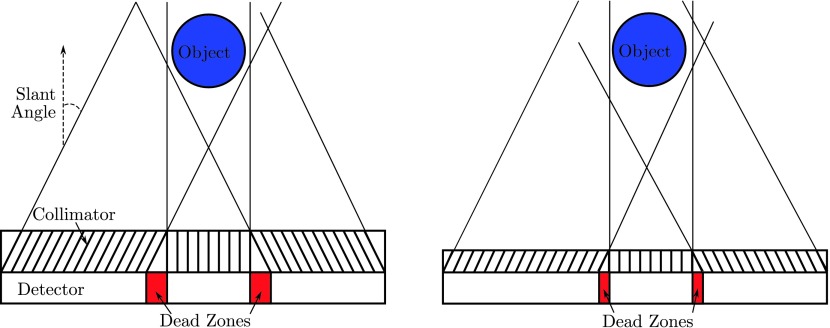
The disadvantage of the segmented parallel-hole collimator is the dead zone between two subcollimators, as shown in Fig. 7 (left). The dead area, which is not used for data acquisition, is defined by the slant angle and the hole length. Thus, we use a thin collimator to reduce the detector dead zone as much as possible (Fig. 7 right). A short hole length also allows more photons to be acquired by the detector, which increases the detector sensitivity. Our previous research has shown that an image reconstructed from a high-sensitivity collimator is less noisy than that from a high-resolution collimator and with collimator-blurring compensation, the high-sensitivity image can have comparable resolution to the high-resolution image.18
FIG. 7.
Left: large dead zones are observed between two subcollimators. Right: dead zones are reduced with shorter hole length.
In fact, a prototype segmented collimator has been fabricated by Nuclear Fields. In our prototype system, the collimator hole length was shortened from 24.05 to 15 mm. At the same time, the hole diameter was increased from 1.11 to 1.9 mm, to further improve the sensitivity. As a result, the collimator hole’s acceptance angle increases from 2.64° to 7.25°. To meet 1.5% penetration requirement at 140 keV, the septal thickness was increased to 0.3 mm. Figure 8 shows a point source image reconstructed from data acquired from the prototype system. The point source is obtained by a capillary tube filled with 99mTc and it is of 1.0 mm diameter and about 2.0 mm axis height. The image resolution was recovered after geometric-blurring compensation.
FIG. 8.
Reconstructed image of a point source without (left) and with (right) resolution recovery. Fifty iterations were used.
3. EVALUATION OF COLLIMATOR
3.A. Theoretical estimation of total sensitivity gain
Compared with the conventional parallel-hole detector, our detector can acquire seven projections simultaneously. The sensitivity gain of the segmented slant-hole collimator over the conventional parallel-hole collimator with the same hole parameters equals
| (3) |
A derivation of sensitivity gain is given in Appendix. We have two detectors, so the total sensitivity of our proposed stationary segmented slant-hole system can have a 5-fold sensitivity gain over a conventional dual-head system, if the hole parameters are the same in both systems.
3.B. Monte Carlo simulation of the stationary cardiac system
A 3D numerical myocardial phantom (NCAT phantom)19 and the gate (geant4 application for tomographic emission) Monte Carlo simulation tool,20,21 which includes the effects of noise, attenuation, collimator–detector response, and scatter, were used for evaluating the segmented slant-hole collimator. The Monte Carlo code simulated the proposed stationary segmented slant-hole SPECT system as well as a conventional dual-head SPECT system. Each head had a FOV of 53.3 × 38.7 cm and was mounted with a low-energy high-resolution (LEHR) collimator (hole length 24.05 mm and diameter 1.11 mm).
The relative radioactivity concentrations of 99mTc in different organs modeled in the NCAT phantom were as follows: heart myocardium: 75; spleen: 60; liver and kidneys: 15; lungs: 4; and body, stomach, rib, and spine: 2. The activities were in arbitrary units. In the clinical practice, the liver and kidneys may have higher uptakes and are truncated in the segments. The effect of high uptakes in these organs was investigated in another set of computer simulations with relative concentration of 75 in the liver and kidneys.
The main clinical task for cardiac SPECT system is detection of defects. To study that a defect in the size of 2 × 2 × 1 cm was placed within the myocardial wall and was evaluated using defect contrast. The activity in the cold lesion is zero.
The gold-standard is the reconstruction from projections at 60 views uniformly spaced over 180° using a conventional rotational SPECT system. For a fair comparison, the total scan time and the system resolution were kept the same in both systems. The rotation radius was set at 26.65 cm. Small FOV (12 × 12 cm) projections were obtained from full-FOV projections by removing the pixels outside the small FOV. The projection data were acquired in 64 × 64 arrays with a pixel size of 6.25 mm. In stationary segmented slant-hole SPECT, the heart has to be placed in the detector center, which is not required by the conventional SPECT. To compare images at the same slice, the heart in the reconstruction of the conventional system was shifted to the image center and a similar slice was displayed. Images were reconstructed using a tailored maximum-likelihood expectation-maximization (ML-EM) algorithm.22 In image reconstruction, collimator blurring was corrected and 35 iterations were applied.
3.C. Assessment of image quality
The main advantage of the segmented slant-hole collimator is sensitivity improvement. To evaluate that the number of counts in the projection data and the value of sensitivity gain over the conventional SPECT system were calculated.
The effects of truncation and number of view-angles were evaluated by a visualization study, to identify whether there are any artifacts and shape distortions in the reconstructed images. Three orthogonal cuts through the heart center were displayed and image profiles through the central column of each cut were shown and compared with the conventional system.
For further quantitative assessment, SNR and cardiac defect contrast were measured to characterize the image noise and reconstructed contrast for known defect locations and volumes. The left ventricle of the myocardium walls was segmented from the reconstructed image. The mean and standard deviation were calculated for the left ventricle. The SNR is the ratio of these two values. The defect contrast was calculated as follows:
| (4) |
where is the average count in the myocardial without a defect and D denotes an area with a defect.
4. RESULTS
In the Monte Carlo simulations, the total photon number acquired by the segment slant-hole system was 2.57 × 10⁶, comparing to 0.52 × 10⁶ counts in the conventional system projection data. Therefore, the measured total sensitivity gain was 4.9, which is very close to the theoretical sensitivity gain. In our prototype system, a thin collimator was used. The measured total sensitivity from the prototype system reaches to 17-fold gain over the conventional dual-head system.
The reconstruction results of the conventional SPECT system and the proposed stationary SPECT system are shown in Fig. 9. In order to study the effects of number of view-angles, an image, which was reconstructed from the same angular sampling as the stationary system but without truncation, was also displayed. In comparison with the reconstruction results of 60 views, 14 views are sufficient to reconstruct the heart without any shape distortion. With the same scan time, the segmented slant-hole SPECT can acquire more photons than the conventional system, so the reconstructed image of the segmented slant-hole system is more uniform around the apex. When the projection data are truncated by the small FOV, the images overall are very well resolved, except for a slight loss of contrast.
FIG. 9.
From top to bottom: reconstruction results of the conventional SPECT using 60 views, the stationary segmented slant-hole SPECT without and with truncation, respectively. The tailored ML-EM algorithm with 35 iterations was used for reconstruction.
Figure 10 compares the profile curves from the central column of the vertical long-axis, short-axis, and horizontal long-axis cuts, respectively. The profile curves of the reconstruction from the segmented slant-hole SPECT follow those from the conventional SPECT system quite well in the ROI.
FIG. 10.

The profiles through the central column of each cut. From left to right: vertical long-axis, short-axis, and horizontal long-axis.
The simulation results with high uptakes in the liver and kidneys were displayed in Fig. 11. Although a large portion of the liver and kidneys are truncated in the segmented slant-hole SPECT system, the high uptakes in these organs have little impact on the myocardium. The shape of heart is well resolved, except for a slight loss of contrast. Similar results were also observed by other groups.23,24
FIG. 11.
Reconstruction results with high uptakes in the liver and kidneys. Top: the conventional SPECT system with 60 views. Bottom: the stationary segmented slant-hole SPECT system. The tailored ML-EM algorithm with 35 iterations was used for reconstruction.
Using the same reconstruction algorithm and iteration number, the SNR for images reconstructed from segmented slant-hole system and conventional system projection data is 4.86 (with the mean of 23 and the standard deviation of 4.7) and 4.07 (with the mean of 5 and the standard deviation of 1.27), respectively. The improvement of the SNR is 19%. The normalized standard deviation is 4.7/23 = 0.207 and 1.27/5 = 0.254 for segmented and conventional systems, separately. Figure 12 shows the short-axis slices containing a defect from the reconstruction and the corresponding slices from the NCAT phantom. The reconstruction is in good agreement with the digital phantom for presence of a cold myocardium lesion and the defect contrast in the reconstruction reaches to 68%.
FIG. 12.

Top: activity distribution in the NCAT phantom with a lateral defect. Bottom: short-axis slices reconstructed from segmented slant-hole projection data show the location of the defect. Images were reconstructed by the tailored ML-EM algorithm with 35 iterations. The nonuniformity is due to the rotation transformation.
5. DISCUSSION AND CONCLUSIONS
We proposed a stationary cardiac SPECT system using segmented slant-hole collimators to acquire 14 views simultaneously. Each detector measures seven views in the transaxial directions. It is very challenging to use a 53.3 × 38.7 cm detection area to measure seven nonoverlapped heart images. Background data truncation problems cannot be avoided in this system. The Monte Carlo simulations have shown that the image reconstructed from the segmented slant-hole system is less noisy than that from the conventional SPECT system with the same acquisition time and image resolution. The effect of truncation on the reconstructed image is slight and no distortion was observed, even when the uptakes in the liver and kidneys are high.
The size of the FOV is limited by the detector size. The good news is that the heart size seems to be unrelated to the patient body habitus, e.g., the left ventricle diameter for a patient above 210 lbs is about 9 cm while it is 8–10 cm for a patient below 186 lbs.17 Patient studies will be performed in the next phase of the research. One of the main aims in the patient studies will be the patient positioning. If the 12 cm FOV is too tight considering cardiac and respiration motions, it will be enlarged with a larger detector size.
The geometry of the stationary system is very different from that of the conventional system. Although the sensitivity was about 5-fold higher than the stationary system, the slant-angle and limited number of angles in the stationary system make the reconstruction more ill-conditioned, leading to a larger condition number. The sensitivity gain of the stationary system is not large enough to overcome the increase of the condition number, so that the SNR gain is not as large as expected. Studies of the trade-off between the system condition number and the sensitivity can be found at Ref. 25.
With respect to the true defect contrast, the measured contrast in Fig. 12 was a little lower due to the scattered photons from the normal myocardium into the defect region and difficulties associated with the defining the volume of defect which is only a few pixels. In this paper, only one phantom with one defect at a fixed location, size, and contrast was simulated. However, the changes might be different for different defect locations, sizes, and noise levels. Future work is needed to evaluate the system performance at various defect detection tasks.
The attenuation is minimal in the LAO direction; nevertheless, an attenuation correction can provide a further improvement to the image quality and accuracy. In our Siemens Symbia TruePoint® SPECT/CT system, x-rays from a CT scan can be used to construct an attenuation map. The attenuation map is not truncated and can be scaled and applied to the forward projection process of the image reconstruction.
The distance from the heart center to the detector may be too large and may cause a reduction of image resolution. In a more advanced design, the patient will be positioned closer to the detector to get higher resolution. Accordingly, the detector will no longer be symmetrically segmented (as seen in Fig. 13). The collimator on the detector at the 90° position in Fig. 3 will have a mirror-reflection design of the collimator on the detector at 0° position.
FIG. 13.

An asymmetric segmented slant-hole collimator.
In conclusion, the Monte Carlo simulations results have confirmed that our 14-view-angle, 2-detector, parallel-hole, stationary cardiac SPECT is able to measure sufficient data for cardiac imaging without any shape distortion and with a significant improvement of sensitivity.
ACKNOWLEDGMENT
This work is supported by NIH Grant No. 1R01HL108350.
APPENDIX: SENSITIVITY GAIN
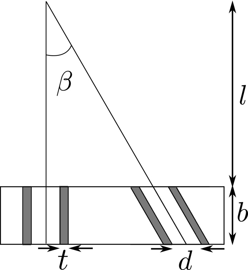
Figure 14 illustrates the parameters for parallel-hole and slant-hole collimators. Collimator efficiency gparallel for parallel-hole collimators is as follows:26
| (A1) |
where leff = l − 2μ−1. Here, μ is the linear attenuation coefficient of the collimator material. Parameters d, t, and K represent the hole diameter, septal thickness, and a constant that depends on hole shape, respectively.
FIG. 14.
Parameters for collimator sensitivity, for Eqs. (A1) and (A2).
The hole length of the slant-hole collimator is elongated along the direction of the slant angle β. The efficiency for slant-hole collimators then becomes
| (A2) |
Therefore, the total sensitivity gain of the segmented slant-hole collimator over the conventional parallel-hole collimator is
| (A3) |
REFERENCES
- 1.Patton J. et al. , “D-SPECT: A new solid state camera for high speed molecular imaging,” J. Nucl. Med. 47(Suppl. 1), 189P (2006). [Google Scholar]
- 2.Patton J., Slomka P., Germano G., and Berman D., “Recent technologic advances in nuclear cardiology,” J. Nucl. Cardiol. 14(4), 501–513 (2007). 10.1016/j.nuclcard.2007.06.003 [DOI] [PubMed] [Google Scholar]
- 3.Babla H., Bai C., and Conwell R., “A triple-head solid state camera for cardiac single photon emission tomography (SPECT),” Proc. SPIE 6319, 63190M–1–63190M–4 (2006). 10.1117/12.683765 [DOI] [Google Scholar]
- 4.http://cardiarc.com/cardiarc_scanner.html, accessed April 23, 2012.
- 5.Liu Z., Kastis G. A., Stevenson G. D., Barrett H. H., Furenlid L. R., Kupinski M. A., Patton D. D., and Wilson D. W., “Quantitative analysis of acute myocardial infarct in rat hearts with ischemia-reperfusion using a high-resolution stationary SPECT system,” J. Nucl. Med. 43(7), 933–939 (2002). [PMC free article] [PubMed] [Google Scholar]
- 6.Beekman F. J. and Vastenhouw B., “Design and simulation of a high-resolution stationary SPECT system for small animals,” Phys. Med. Biol. 49, 4579–4592 (2004). 10.1088/0031-9155/49/19/009 [DOI] [PubMed] [Google Scholar]
- 7.Funk T., Kirch D. L., Koss J. E., Botvinick E., and Hasegawa B. H., “A novel approach to multipinhole SPECT for myocardial perfusion imaging,” J. Nucl. Med. 47(4), 595–602 (2006). [PubMed] [Google Scholar]
- 8.Steele P. P., Kirch D. L., and Koss J. E., “Comparison of simultaneous dual-isotope multipinhole SPECT with rotational SPECT in a group of patients with coronary artery disease,” J. Nucl. Med. 49(7), 1080–1089 (2008). 10.2967/jnumed.107.040915 [DOI] [PubMed] [Google Scholar]
- 9.Esteves F. P., Raggi P., Folks R. D., Keidar Z., Wells Askew J., Rispler S., OConnor M. K., Verdes L., and Garcia E. V., “Novel solid-state-detector dedicated cardiac camera for fast myocardial perfusion imaging: Multicenter comparison with standard dual detector cameras,” J. Nucl. Cardiol. 16(6), 927–934 (2009). 10.1007/s12350-009-9137-2 [DOI] [PMC free article] [PubMed] [Google Scholar]
- 10.Bocher M., Blevis I. M., Tsukerman L., Shrem Y., Kovalski G., and Volokh L., “A fast cardiac gamma camera with dynamic SPECT capabilities: Design, system validation and future potential,” Eur. J. Nucl. Med. Mol. Imaging 37(10), 1887–1902 (2010). 10.1007/s00259-010-1488-z [DOI] [PMC free article] [PubMed] [Google Scholar]
- 11.Schramm N. U., Ebel G., Engeland U., Schurrat T., Behe M., and Behr T. M., “High-resolution SPECT using multipinhole collimation,” IEEE Trans. Nucl. Sci. 50(3), 315–320 (2003). 10.1109/TNS.2003.812437 [DOI] [Google Scholar]
- 12.Bowen J. D., Huang Q., Ellin J. R., Lee T., Shrestha U., Gullberg G. T., and Seo Y., “Design and performance evaluation of a 20-aperture multipinhole collimator for myocardial perfusion imaging applications,” Phys. Med. Biol. 58(20), 7209–7226 (2013). 10.1088/0031-9155/58/20/7209 [DOI] [PMC free article] [PubMed] [Google Scholar]
- 13.Smith M. F., Majewski S., and Weisenberger A. G., “Optimizing pinhole and parallel hole collimation for scintimammography with compact pixellated detectors,” IEEE Trans. Nucl. Sci. 50(3), 321–326 (2003). 10.1109/TNS.2003.812436 [DOI] [Google Scholar]
- 14.Slomka P. J., Berman D. S., and Germano G., “New cardiac cameras: Single-photon emission CT and PET,” Seminars in Nuclear Medicine 44, 232–251 (2014). 10.1053/j.semnuclmed.2014.04.003 [DOI] [PubMed] [Google Scholar]
- 15.Oberman A., Myers A. R., Karunas T. M., and Epstein F. H., “Heart size of adults in a natural population-Tecumseh, Michigan: Variation by sex, age, height, and weight,” Circulation 35(4), 724–733 (1967). 10.1161/01.CIR.35.4.724 [DOI] [PubMed] [Google Scholar]
- 16.Barclay A. B., Eisner R. L., and DiBella E. V. R., “Construction of a thorax model database from clinical PET attenuation scans,” Annual Meeting of the Society of Nuclear Medicine, Minneapolis, MN, 1995.
- 17.Devi S., Clackdoyle R., and Christian P. E., “Torso and heart dimensions of cardiac SPECT patients,” in Conference Record 1997 Nuclear Science Symposium and Medical Imaging Conference, Albuquerque, NM (IEEE, Albuquerque, NM, 1997), Vol.2, pp. 1087–1091. 10.1109/NSSMIC.1997.670498 [DOI] [Google Scholar]
- 18.Zhang B. and Zeng G. L., “High-resolution versus high-sensitivity SPECT imaging with geometric blurring compensation for various parallel-hole collimation geometries,” IEEE Trans. Inf. Technol. Biomed. 14(4), 1121–1127 (2010). 10.1109/TITB.2010.2050145 [DOI] [PMC free article] [PubMed] [Google Scholar]
- 19.Segars W. P., “Development of a new dynamic NURBS-based cardiac torso (NCAT) phantom,” Ph.D. thesis, University of North Carolina, 2001. [Google Scholar]
- 20.Strulab D., Santin G., Lazaro D., Breton V., and Morel C., “ gate (geant4 application for tomographic emission): A PET/SPECT general-purpose simulation platform,” Nucl. Phys. B, Proc. Suppl. 125, 75–79 (2003). 10.1016/S0920-5632(03)90969-8 [DOI] [Google Scholar]
- 21.Jan S. et al. , “ gate: A simulation toolkit for PET and SPECT,” Phys. Med. Biol. 49(19), 4543–4561 (2004). 10.1088/0031-9155/49/19/007 [DOI] [PMC free article] [PubMed] [Google Scholar]
- 22.Mao Y. and Zeng G. L., “A tailored ML-EM algorithm for reconstruction of truncated projection data using few view angles,” Phys. Med. Biol. 58(12), N157–N169 (2013). 10.1088/0031-9155/58/12/N157 [DOI] [PMC free article] [PubMed] [Google Scholar]
- 23.Gregoriou G. K., Tsui B. M. W., and Gullberg G. T., “Effect of truncated projections on defect detection in attenuation-compensated fanbeam cardiac SPECT,” J. Nucl. Med. 39(1), 166–175 (1998). [PubMed] [Google Scholar]
- 24.Xiao J., Verzijlbergen F. J., Viergever M. A., and Beekman F. J., “Small field-of-view dedicated cardiac spect systems: Impact of projection truncation,” Eur. J. Nucl. Med. Mol. Imaging 37(3), 528–536 (2010). 10.1007/s00259-009-1223-9 [DOI] [PMC free article] [PubMed] [Google Scholar]
- 25.Zeng G. L., “Revisit of combined parallel-beam/cone-beam or fan-beam/cone-beam imaging,” Med. Phys. 40(10), 100701 (5pp.) (2013). 10.1118/1.4820373 [DOI] [PMC free article] [PubMed] [Google Scholar]
- 26.Cherry S. R., Sorenson J. A., and Phelps M. E., Physics in Nuclear Medicine (Elsevier Health Sciences, Philadelphia, PA, 2012). [Google Scholar]


