Abstract
The hydrodynamics of an archetypal low-Reynolds number swimmer, called “squirmer”, near a wall has been numerically studied. For a single squirmer, depending on the swimming mechanism, three different modes are distinguished: (a) the squirmer escaping from the wall, (b) the squirmer swimming along the wall at a constant distance and orientation angle, and (c) the squirmer swimming near the wall in a periodic trajectory. The role of inertial effects on the near-wall motion of the squirmer is quantified. The dynamics of multiple squirmers swimming between two walls is found to be very different from a single squirmer. Near-wall accumulation of squirmers are observed. At a relatively small concentration c = 0.1, around 60 – 80% of the squirmers are accumulated near the walls and attraction of pushers and pullers towards the wall is stronger than neutral squirmers. Near-wall squirmers orient normal to the wall, while in the bulk region, the squirmers are mostly oriented parallel to the wall. At a high concentration, c = 0.4, the percentage of the near-wall squirmers is around 40%. The orientation angle of squirmers in the bulk region is more uniformly distributed at high concentrations. In the near-wall region, pullers repel each other, while pushers are attracted to each other and form clusters.
I. Introduction
Biolocomotion in a low Reynolds number regime near a no-slip wall is a subject of growing interest in recent years for its importance in many health and environmental problems [1, 2]. For example, accumulation of bacteria near the surface and the formation of biofilms are closely related to many types of microbial infections [3]. Spermatozoa swimming in the female reproductive tract is another common example [4]. Studies have demonstrated that the presence of boundaries significantly affects the swimming speed and energetic properties of micro-swimmers [5–7]. Furthermore, recent experimental studies have observed many unexpected interesting behaviors for swimming organisms near a boundary, including the circular orbit of E. coli above a flat surface [8], wall induced accumulation of organisms [9–12] and the “dancing” motion of pairs of Volvox near a solid boundary [13].
The inertial effects are important for many of planktonic swimmers in marine environments, such as larvae and Pleurobrachia. Small organisms use inertia to change their swimming direction, attack a prey or escape from a predator [14, 15]. Wang and Ardekani [16, 17] analytically quantified the inertial effects by deriving the fundamental equation of motion for small organisms swimming in an unbounded quiescent fluid environment. The role of boundaries on the swimming of small organisms in a nonzero-Reynolds-number regime is of great importance. For example, the accumulation of larvae near the surface has a significant influence on the metamorphosis and survival of larvae [18].
Simplified swimming models have been widely used to investigate the dynamics of confined swimmers in a zero-Reynolds-number regime. The work of Zargar et al. [19] analyzed the influence of a wall on the dynamics of a three-sphere swimmer in the close proximity of a boundary. It is shown that the swimmer can swim towards or escape from the wall, depending on the initial angle and distance from the wall. The work of Or et al. [20] studied the dynamics of swimmers formed by small networks of rotating spheres attached by rigid rods. In their simulation, mobility matrices for multiple interacting spherical particles in the presence of a flat plane were approximately calculated by accounting for the far-field hydrodynamic interactions. Their results show that the swimmer may have a marginally stable motion or a periodic motion depending on the arrangement of the spheres. Similar swimming dynamics was reported in the work of Crowdy and Or [21] for a two-dimensional treadmilling swimmer model near a no-slip wall. The treadmilling swimmer was also utilized to study the swimming dynamics near a wall with a gap. Stable equilibrium points for the swimmer in the gap region, as well as, Hopf bifurcations and periodic bound states were observed [22]. The work of Dunstan et al. [23] modeled a bacterial cell by using two spheres of different radii at a constant distance. The effect of the flagella was modeled by imposing a force on the tail sphere as well as adding equal and opposite torques on the two spheres. Their results show three different swimming behaviors depending on the initial condition: swimming in circles in contact with the wall, swimming in circles at a finite distance from the wall and swimming away from the wall. Spagnolie and Lauga [24] provided a detailed comparison of the hydrodynamics of micro-swimmers near a boundary using far-field approximations and numerical solutions of the Stokes equation. They showed that the far-field approximation is surprisingly accurate for spherical swimmers when the distance between the center of the swimmer and the wall is larger than its diameter. However, the fundamental singularities of the Stokes equation cannot accurately account for the near-field effects when the swimmer comes close to the boundary. Here in this work, Navier-Stokes equations are directly solved to capture the hydrodynamic interaction of a single swimmer and a suspension of swimmers near a wall in a small, but nonzero, Reynolds number regime.
One of the widely used swimmer models called “squirmer”, is introduced by Lighthill [25] and Blake [26] to model the ciliated microorganisms such as Volvox and Paramecium. Other studies have extended the model to general shape [27], porous prolate-spheroidal [28], and small-amplitude deformable squirmers [29]. Here, we consider a spherical squirmer with a tangential surface deformation given as
| (1) |
where e is the orientation vector of the squirmer, Bn is the nth mode of the tangential squirming velocity [26], Pn is the nthe Legendre polynomial, is its derivative, and r is the position vector. Similar to most previous studies [30–37], we only consider the first two squirming modes and consequently the magnitude of the tangential velocity is written as
| (2) |
where θ is the polar angle measured from the swimming direction, B1 and B2 are the first two squirming modes. The parameter β = B2/B1 distinguishes three kinds of swimmers: β > 0, corresponds to a puller generating thrust in front of the body such as Chlamydomonas; β < 0, corresponds to a pusher generating thrust behind the body such as most bacteria; β = 0 corresponds to a neutral squirmer, generating a symmetric flow field, such as Volvox. In the Stokes regime, the swimming speed of a squirmer in an unbounded domain is U0 = 2B1/3. The squirmer model has been widely used to study the dynamics of a single microswimmer, nutrient uptake [30, 38], bio-mixing [39], unsteady propulsion of small organisms [17] as well as the effects of density stratification on the self-propulsion [31]. Recently, Zhu et al. [32] studied the locomotion of a squirmer in a capillary tube and found that a neutral squirmer generally follows a helical trajectory; a puller displays a stable locomotion along the tube, while a pusher crashes into the wall. Ishikawa, Pedley, and coworkers have studied the dynamics of multiple squirmers in an unbounded fluid in the Stokes regime, including the hydrodynamic interaction between two squirmers [33], rheology and diffusion of a suspension of squirmers [34, 35], collective behavior [36], and vertical dispersion of squirmers in a shear flow [37].
Microorganisms are usually observed in high concentrations, where the interaction between microorganisms are important and they often exhibit collective behaviors resulting in swarms and vortices of large scales [40]. Previous experiments show that a suspension of microorganisms results in the variation of fluid viscosity [41], superdiffusion in short times [42], and enhanced mixing [41]. Hydrodynamic interaction of spherical particles near a wall or between two walls in a zero-Reynolds-number regime has been extensively studied using multipole expansion method and Stokesian Dynamics [43–45]. The algorithm developed by Bhattacharya et al. accurately calculates the many-particle friction matrix by using spherical and Cartesian representation of Stokes flow to capture the interaction of the fluid with the particles and walls, respectively [45]. This method can be successfully applied to evaluate the friction matrix for a single sphere, a pair of spheres, and linear chains of spheres between two walls [46]. Based on the dumbbell swimmer model of two beads connected by a rigid rod, Underhill et al. [47] studied the diffusion and spatial correlation of swimmers as well as the correlations of stress and velocity [48]. Using the same model, Hernández-Ortiz et al. [49, 50] studied the dynamics of suspension of swimmers between two walls and found that the swimmers aggregate near the wall at low concentrations, while at high concentrations, this distribution is disrupted by large-scale coherent motions. The diffusion and spatial correlation of swimmers are also affected by the confined geometry. Their model treated the swimmers as point force dipoles and the swimmer-swimmer and swimmer-wall interactions are approximated using an excluded volume force. Wensink and Löwen [51] studied the suspension of self-propelled colloidal rods in a channel using two-dimensional Brownian dynamics simulation. Their results show that the aggregated self-propelled rods near the channel wall form “hedgehog”-shaped clusters with most of the rods pointing towards the wall.
In this paper, we investigate the dynamics of a single and a collection of squirmer(s) near a no-slip wall in a low-Reynolds-number regime. By directly solving the Navier-Stokes equation, the inertial effects are included and the motion of small swimming organisms near a solid surface is accurately captured.
II. Numerical method
The distributed Lagrange multiplier based finite volume method is used in this study and details of the method can be found in [52, 53]. The Navier-Stokes equations for an incompressible Newtonian fluid are solved in the entire computational domain
| (3a) |
| (3b) |
where u is the velocity, p is the pressure, I is the identity tensor, τ = μ(∇u + ∇uT) is the viscous stress, and μ is the viscosity. The density ρ is equal to the particle density ρp inside the squirmer and equal to the fluid density ρf in the fluid domain. In this study, we set ρp = ρf since the density of microorganisms is usually close to the background fluid. A rigid particle and a self-propelled particle can be modeled by adding a source term to the Navier-Stokes equation. The forcing term in each iteration is calculated as
| (4) |
where U is the translational velocity of the particle (inert or self-propelled), ωp is the particle angular velocity, ui is the imposed velocity causing the self-propulsion, f* is the force calculated in the previous iteration, α is a dimensionless factor whose value affects the convergence rate but not the solution, ϕ is the volume fraction occupied by the particle in each computational cell (ϕ = 1 inside, ϕ = 0 outside and 0 < ϕ < 1 for the cells at the surface of the particle). The velocity field u is obtained by solving Eq. (3). To recover the tangential velocity on the surface of the squirmer (given in Eq. (2)), we impose the following solenoidal velocity ui inside the squirmer
| (5) |
where a is the radius of the squirmer, er and eθ are the unit vectors along r and θ directions, m is an arbitrary positive integer, where the simulation results are independent of its value. It should be noted that ui is zero for an inert particle. The particle translational and angular velocities are calculated as
| (6) |
| (7) |
where Vp, Mp and Ip are the volume, mass and moment of inertia of the particle. The imposed velocity leads to a zero translational and rotational velocity for the particle (i.e ∫VpuidV = 0 and ∫Vpr × uidV = 0). Iterations are repeated until the maximum of Euclidean norm of (f − f*) / f and the normalized residual falls below the specified tolerance of 10−3. The normalized residual is defined as
| (8) |
The velocity field inside the particle for the converged solution is u = U + ωp × r + ui. It is straight forward to demonstrate that the converged solution is the equivalent of the particle equation of motion:
| (9) |
where dS is the surface differential element. Combining Eqs. (4)-(7), one can show that ∫VpfdV = 0. Integrating Eq. (3a) over the particle volume and using the Reynolds transport theorem lead to:
| (10) |
which is equivalent to Eq. (9). This method has been extensively used for the motion of inert particles in viscous fluids and verified in our previous publications [53–57].
Simulations are conducted using a finite volume method on a fixed staggered grid. A conventional operator splitting method is applied to enforce the continuity equation. The second-order TVD (total variation diminishing) Runge-Kutta method is used for time marching. The spatial derivatives in the convection term are evaluated using the QUICK (Quadratic Upstream Interpolation for Convective Kinetics) scheme and the diffusion terms are discretized using the central difference scheme. The results are normalized by the characteristic length a, velocity U0 = 2B1/3, and time a/U0.
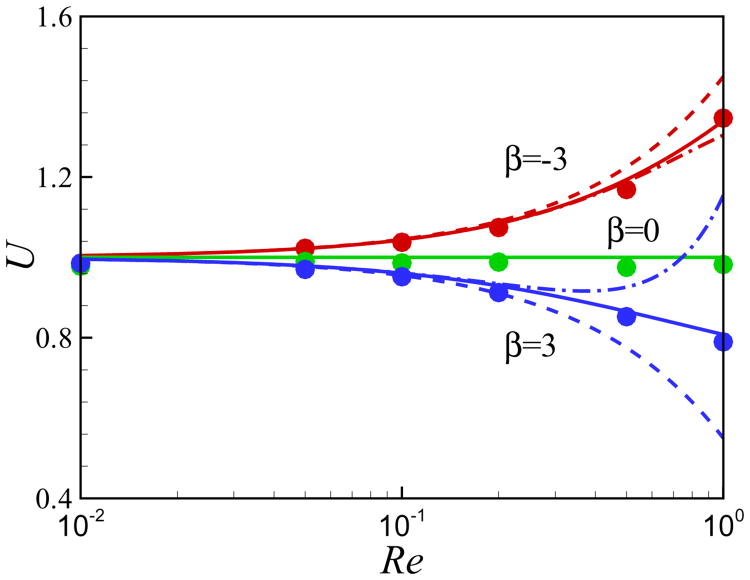
We first validate the motion of a single squirmer in an unbounded fluid at a finite Reynolds number defined as Re = ρU0a/μ. The comparison between the present numerical results for the steady swimming speed and the analytical results, obtained using perturbation theory, [17, 58] is illustrated in Fig. 1. The first order solution for the swimming speed of a squirmer in an unbounded domain is U ≈ 1 − 0.15β Re [17]. The swimming speed U of the neutral squirmer does not change with the Reynolds number. The swimming speed of a pusher increases with Re and our results are in good agreement with the analytical results at small values of Reynolds number. The swimming speed of a puller decreases with Re. At Re > 0.2, the first-order solution of Wang and Ardekani [17] and the second-order solution of Khair and Chisholm [58] starts to fail. Our results agree with Eq. (41) of [58].
Fig. 1.
(Color online) Comparison of the results for the steady swimming of a squirmer in an unbounded domain at finite Re. Symbols: present numerical results, dashed lines: Eq. (39) from [17] (first order), dashdot lines: Eq. (40) of [58] (second order), solid lines: Eq. (41) of [58]. The domain size for the computational results is 40 × 40 × 40.
Here in this study, we focus on the motion of a single squirmer near a wall and a suspension of squirmers between two walls. The schematic of a single squirmer near a wall is shown in Fig. 2. The distance between the center of the squirmer and the wall is h and the orientation angle of the squirmer from the horizontal direction is α. The wall is located at y = 0 and the squirmer moves in the x − y plane. For the cases of multiple squirmers, there are two walls at y = 0 and y = L and α corresponds to the orientation of the squirmer relative to the nearest wall.
Fig. 2.
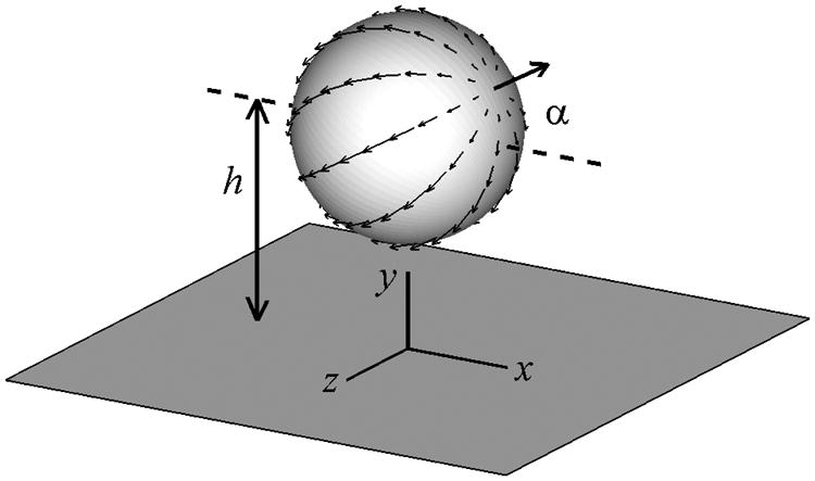
Schematic of a squirmer near a wall.
When the squirmer approaches the wall or another squirmer, the high pressure in the thin film between the squirmers and the wall prevents any unphysical overlaps. However, a very small grid resolution is needed to properly capture this dynamic process and consequently it is computationally expensive. As mentioned in [24], a short-range repulsive force [59] is necessary to prevent squirmer-wall or squirmer-squirmer overlaps. The repulsive force during the squirmer-wall or squirmer-squirmer collision is defined as:
| (11) |
where is the characteristic force, ε = 10−4 is a small positive number, d is the distance between the center of the squirmer and the wall or the distance between two squirmers, dmin = a or 2a is the corresponding minimum possible distance, dr is the force range and is usually set to be the smallest grid size Δ in the computational domain [59]. The direction of the repulsive force ec is normal to the wall or along the line of center of the two squirmers. The above mentioned repulsive force has been widely used to handle the collision between particles and walls [57, 59]. Besides the formula used here, another form of repulsive force based on soft-sphere collision model is used in the numerical simulation of nutrient uptake of a suspension of squirmers in a thin film [30].
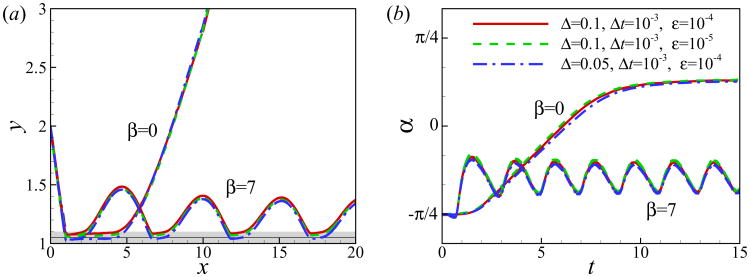
To check the convergence of the results, simulations of the near-wall motion of a neutral squirmer and a puller are conducted for different values of mesh size, time step and magnitude of repulsive force. The size of computational domain is 64 × 25.6 × 12.8. The no-slip boundary condition is used on the wall and the far field boundary condition is used at other boundaries of the domain. The squirmer is initially located at h0 = 2, α0 = −π/4 and Re = 1. As shown in Fig. 3, the computed results are independent of the grid size, time step and magnitude of the repulsive force. Consequently, for the calculations presented in this work, twenty grid points are used across the squirmer diameter and the time step is set to Δt = 1 × 10⁻³.
Fig. 3.
(Color online) (a) Trajectory and (b) temporal evolution of orientation angle α for squirmers of β = 0 and 7 at Re = 1 and initially located at α0 = −π/4, h0 = 2. Gray area and the black line in (a) show the area inside which the gap between the squirmer and the wall is less than one mesh size of Δ = 0.1 and Δ = 0.05, respectively.
III. Results and Discussion
A. Swimming dynamics of a single squirmer near a wall
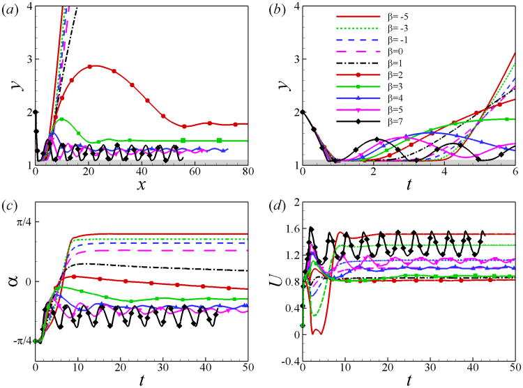
Fig. 4 shows the trajectory as well as the time history of orientation angle α and swimming speed U of the squirmer for different values of β. The squirmer collides with the wall at t ≃ 0.8, then it swims along the wall for a certain period of time referred to as the “contact time” and finally swims away from the wall. The contact time decrease as β increases. When squirmers detached from the wall, three different swimming modes are observed depending on the values of β: (1) Squirmers of β ≤ 1 will swim away from the wall with a positive angle. (2) Squirmers of 2 ≤ β ≤ 5 oscillate near the wall and eventually swim along the wall with a constant distance and a negative angle. It should be noted that the damping ratio for the cases of β = 4 and 5 is small and their oscillations is not fully damped during the simulation time. (3) Squirmers of β ≥ 7 will swim in a cyclic motion, bouncing on the wall. The amplitude of the cyclic motion is small compared to the wavelength. Similar steady and periodic swimming modes along the wall have been observed in [20] using a three-sphere swimmer model. For the squirmers swimming away form the wall, the swimming speed is recovered to its value for a squirmer in an unbounded domain. For β ≤ 1, the swimmers scape from the wall and their steady swimming speed decreases as β increases, which is consistent with analytical results of inertial squirmer in an unbounded domain [17]. On the other hand, pullers of β > 2 are trapped near the wall and their swimming speed increases with β.
Fig. 4.
(Color online) (a) Trajectory and (b) temporal evolution of distance away from the wall y, (c) orientation angle α and (d) swimming speed U for squirmers of various β at Re = 1, initially located at h0 = 2 and α0 = −π/4.
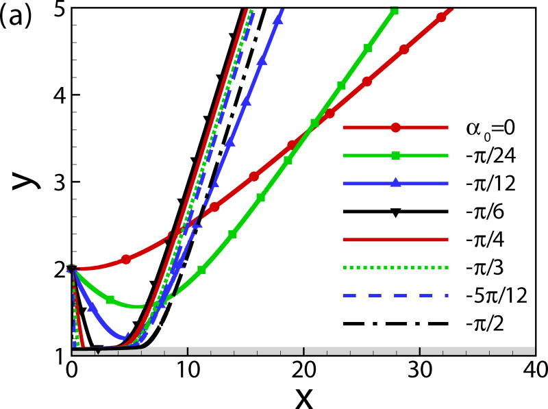
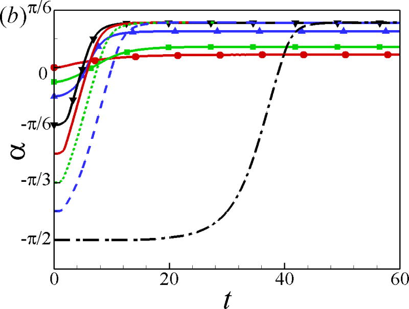
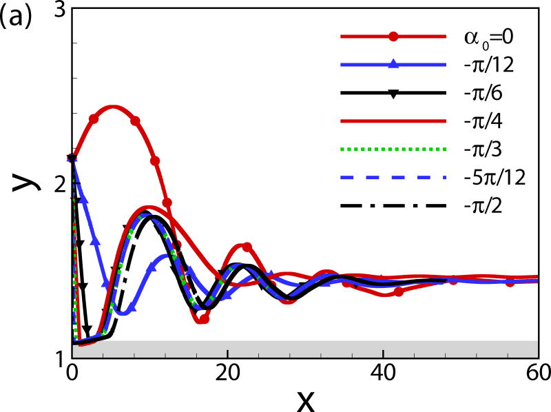
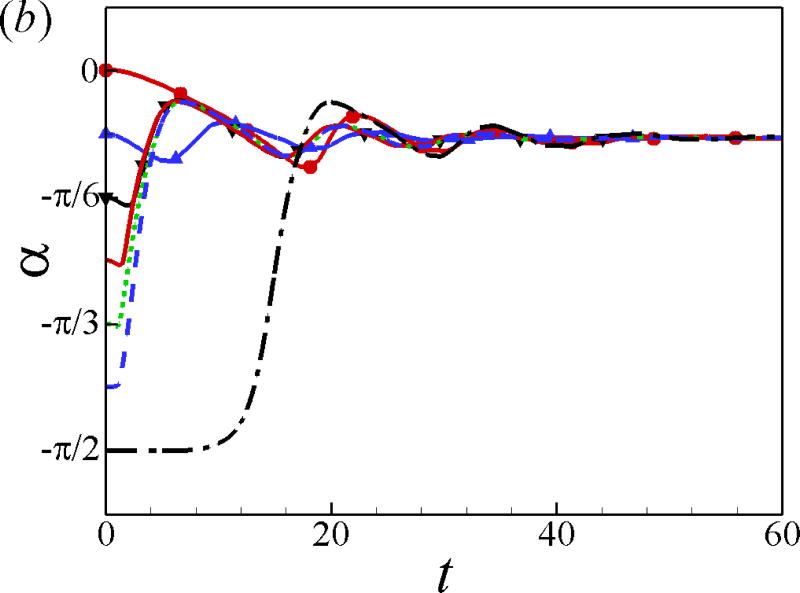
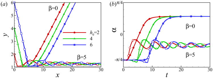
The effects of the initial angle and the initial height are also studied. The effects of the wall on the squirmer weakens for α0 > 0 since the squirmer swims away from the wall. Therefore, we mainly focus on the cases of α0 ≤ 0. For the neutral squirmers at h0 = 2 and Re = 1 in Fig. 5, the trajectories are affected by the initial angle while the swimming mode remains the same. For angles α0 ≥ −π/12, the squirmer rotates away from the wall before getting to a close contact with the wall, whereas for initial angles α0 ≤ −π/6, the squirmer collides with the wall and rotates away from the wall in a near-wall contact region. The squirmer eventually escapes the wall with a same final angle of αf ≃ 0.4. In the work of [24], final angle αf ≃ 0.4 and 0.35 were derived from the boundary-integral simulation and far-field approximation, respectively. The role of initial angle of a puller on the final angle and distance from the wall is shown in Fig. 6. All the squirmers of β = 3 at h0 = 2 and Re = 1 finally reach to a steady state away from the wall with a constant distance hf ≃ 1.47 and final angle αf = −0.23, independent of the initial angles. The effects of the initial height of the squirmers are plotted in Fig. 7; the initial height affects the collision time between the squirmer and the wall but not the swimming mode.
Fig. 5.
(Color online) (a) Trajectory and (b) temporal evolution of α for squirmers of β = 0, h0 = 2, and Re = 1.
Fig. 6.
(Color online) (a) Trajectory and (b) temporal evolution of α for squirmers of β = 3, h0 = 2, and Re = 1.
Fig. 7.
(Color online) (a) Trajectory and (b) temporal evolution of α for squirmers of different initial heights at Re = 1 and α0 = −π/4.
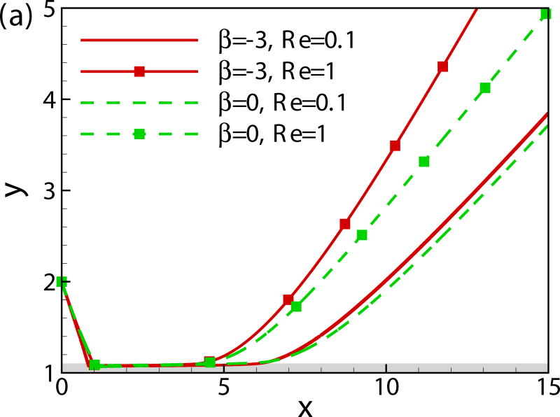
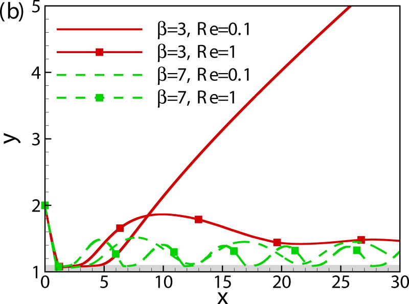
In Fig. 8, we compare the trajectories of squirmers of β = −3, 0, 3 and 7 at α0 = −π/4 and h0 = 2 for two different values of Reynolds number (Re = 0.1 and 1). The initial contact time decreases with Reynolds number. The pusher and neutral swimmer escape from the wall for both values of Reynolds number, whereas puller of β = 3 escapes from the wall at Re = 0.1 and is entrapped near the wall at Re = 1. At larger values of β, the puller is entrapped for both values of Reynolds number, but the one at Re = 1 has a larger bouncing frequency. In summary, the inertial effect decreases the initial wall contact time independent of the squirming type, but it leads to a stronger attraction towards the wall for the puller.
Fig. 8.
(Color online) Trajectory of squirmers of (a) β = −3 and 0 (b) β = 3 and 7 at different Reynolds numbers.
B. Swimming dynamics of multiple squirmers between two walls
We examine the swimming dynamics of a suspension of squirmers between two walls. The simulation is conducted in a cubic domain of [0, 13.89] × [0, 13.89] × [0, 13.89] with two no-slip walls at y = 0 and y = 13.89. Periodic conditions are used along x and z directions. Without any overlap, squirmers are initially randomly placed in a fluid otherwise at rest and their orientations are also randomly initialized. Three cases of β = 0, 3, and −3 at volume concentration c = (4πN)/(3L3) = 0.1 are simulated. The case of β = 0 at c = 0.4 is also studied to consider the role of concentration. N = 64 and 256 squirmers are modeled for the two concentrations, respectively. Across the diameter of the squirmer, there are around 20 grid points for cases of c = 0.1 and 10 grids for c = 0.4, the time step is Δt = 1 × 10⁻³. The Reynolds number is Re = 1 for all cases.
Fig. 9 shows the spatial distribution of squirmers at t = 100 at which the system has reached a statistical steady state. White and black points show the front and trailing ends of squirmers, respectively. At concentration c = 0.1, squirmers are accumulated near the walls for all values of β. Aggregation of pushers and pullers near the wall is stronger compared to the neutral squirmers. At high concentrations, squirmers are very close to each other and the accumulation near the walls is not obvious from Fig. 9. Another interesting phenomena is that there is a strong tendency for squirmers to orient towards the walls in the near-wall region.
Fig. 9.
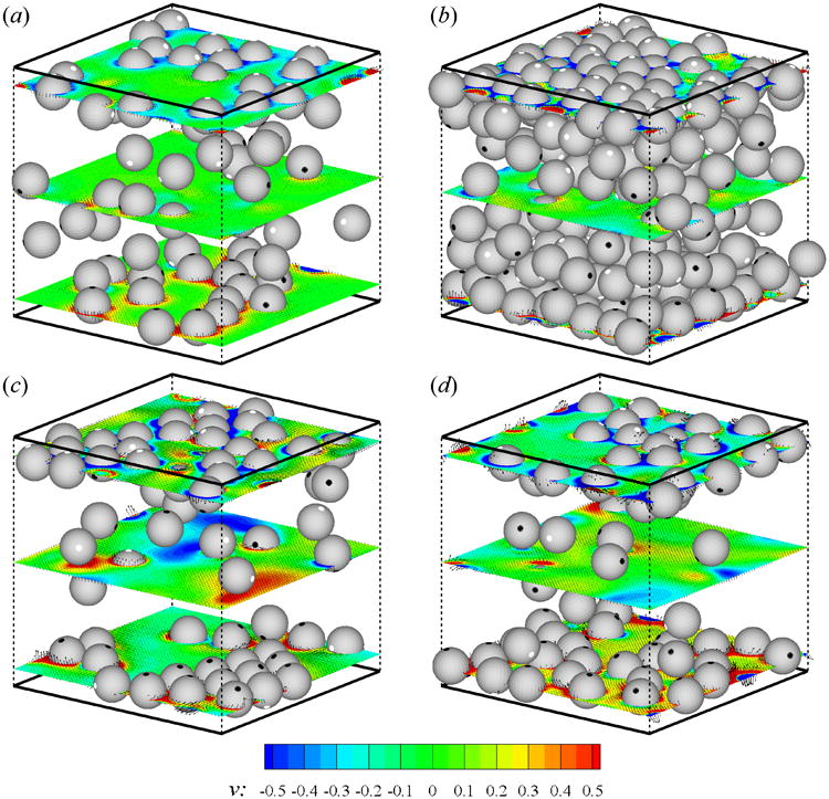
(Color online) Distribution of squirmers of (a) β = 0, c = 0.1, (b) β = 0, c = 0.4, (c) β = −3, c = 0.1, and (d) β = 3, c = 0.1. Thick solid lines on the top and bottom show the plane walls, dashed lines show the computational domain. The front and trailing ends of squirmers are shown with white and black points, respectively. The contourplot of v and the velocity vectors on horizontal planes are shown on three slices at y = 1,6.94, and 12.89. The data is shown at every two points for cases of c = 0.1.
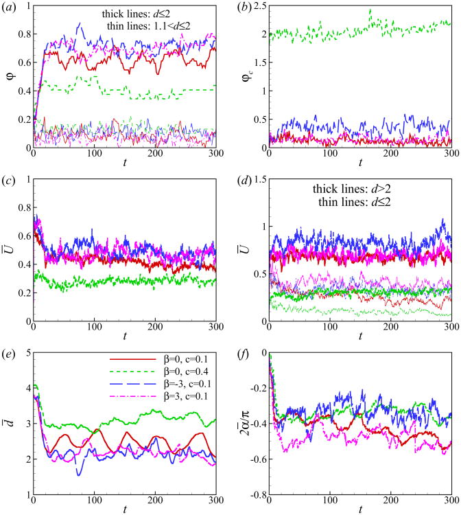
We now quantitatively characterize the hydrodynamic interaction between the squirmers and the walls. We first define the percentage of near-wall squirmers φ (see Fig. 10(a)) and the number of the collisions between squirmers normalized by the total number of squirmers φc (see Fig. 10(b)). Squirmer n is considered to be near the wall when its distance from the wall dn = min(yn(t), L − yn(t)) is smaller than a cutoff distance dcut. Squirmer-averaged properties are plotted in Figs. 10(c)∼(f): the squirmer-averaged swimming speed , the squirmer-averaged distance from the wall and the squirmer-averaged orientation angle , where αn is the orientation angle of the squirmer n from the nearest wall. All the cases reach a statistical state at t ≃ 20. In the case of c = 0.1, around 60 ∼ 80% of squirmers swim within the distance of one diameter away from the wall, and most of them are actually in contact with the wall. In the suspension of squirmers at c = 0.4, the percentage of the near-wall squirmers is lower due to the dense packing and dominance of the steric interactions between squirmers. The percentage of squirmers undergoing collisions is shown in Fig. 10(b). There are more collisions among pushers compared to pullers and neutral squirmers at c = 0.1, which can be due to the larger swimming speed of pushers at Re = 1. At a high concentration, c = 0.4, φc increases dramatically, reaching to about 2.
Fig. 10.
(Color online) Time evolution of (a) percentage of near-wall squirmers φ, (b) percentage of colliding squirmers normalized by the total number of squirmers φc, (c) squirmer-averaged swimming speed Ū, (d) squirmer-averaged swimming speed for squirmers inside and outside the near-wall region distinguished by dcut = 2, (e) squirmer-averaged distance from the wall d̄ and (f) squirmer-averaged orientation angle ᾱ.
Fig. 10(c) shows that the average swimming speed Ū decreases and reaches a statistically steady state at t ≃ 20. At small concentrations, Ū is approximately the same for different types of squirmers. At a high concentration (i.e. c = 0.4), the squirmer-averaged swimming speed Ū is reduced. Fig. 10(d) shows the time evolution of average swimming speed for the squirmers in the near-wall region and in the bulk region. In the near-wall region, pullers swim faster; while in the bulk region, pushers swim faster. These results are consistent with the results of a single squirmer shown in Fig. 4(d). We use the data of t > 20 to calculate the time-averaged speed over the total numbers of squirmers : . For β = 0, −3, and 3 at c = 0.1, 〈Ū〉 is 0.44, 0.46, and 0.51, respectively, and 0.27 for β = 0 at c = 0.4. Recall form Fig. 1, the steady swimming speed of a single squirmer in an unbounded domain at Re = 1 is 1, 1.35, 0.79 for β = 0, −3 and 3, respectively. When near the wall, the swimming speed of a pusher decreases, while it increases for a puller as seen in 4(d). For a wall-trapped puller of β = 3 swimming along the wall, the steady speed is around 0.86. In summary, in all our cases, the average swimming speed of suspension of squirmers decreases to around 30–60% of the speed of a single squirmer due to the effects of the walls and collision between squirmers.
Figs. 10(e) and 10(f), show that both squirmer-averaged distance from the wall d̄ and squirmer-averaged orientation angle ᾱ decrease with time, indicating the tendency of squirmers to accumulate near the wall and to orient towards the wall. The distribution of squirmers is furthermore quantified by calculating the probability distribution function f(ϕ) which is defined as
| (12) |
and
| (13) |
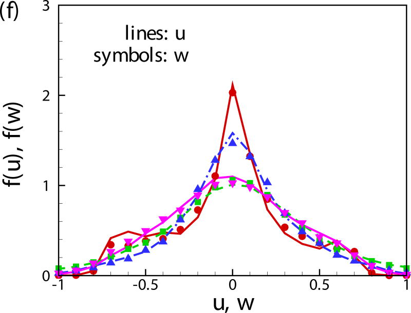
where ϕ is the vertical position y and orientation angle α in Figs. 11(a)∼(f), and Δϕ is the interval of ϕ which is set to Δy = 1.389, Δα = 0.05π and Δu = Δv = Δw = 0.1. The choice of Δϕ does not qualitatively change the results. The symbol 〈〉 represents a time-averaged quantity.
Fig. 11.
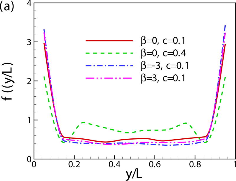
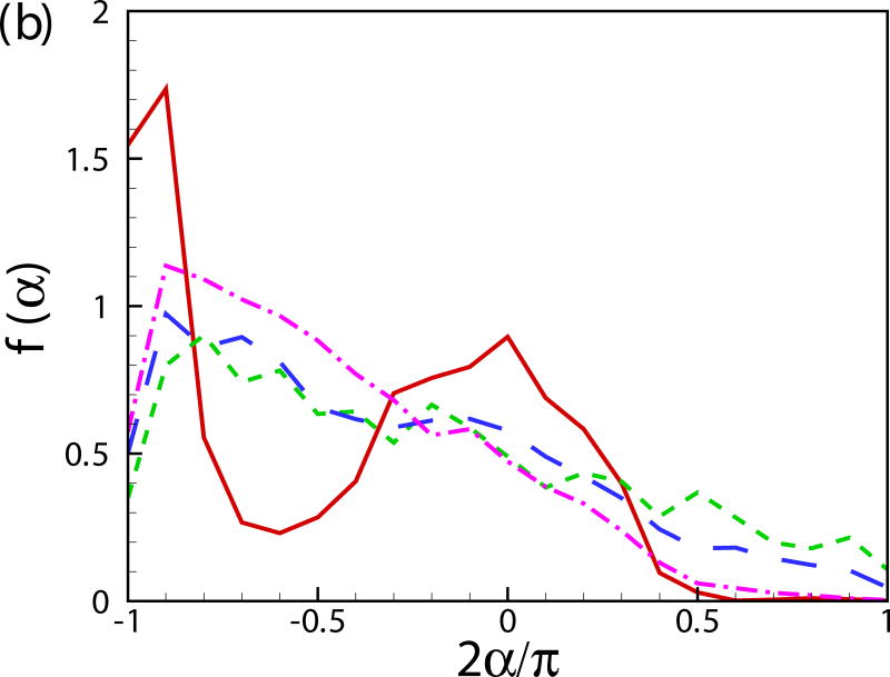
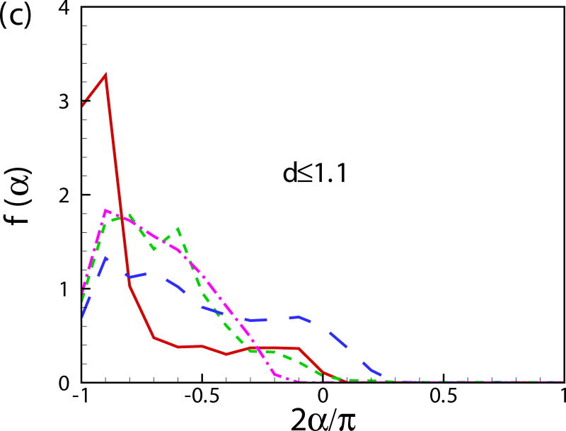
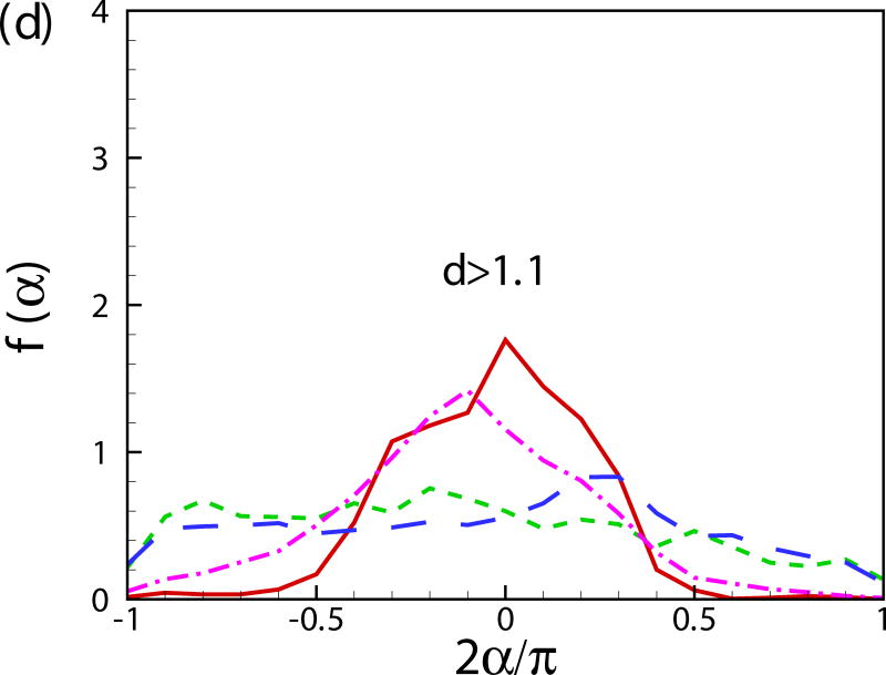
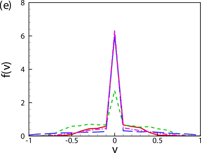
(Color online) The probability distribution function of (a) vertical position of squirmers, (b) orientation angle α with respect to the nearest wall, (c) α for the near-wall squirmers, (d) α for the squirmers in the bulk region, (e) vertical velocity component v and (f) velocity components u and w.
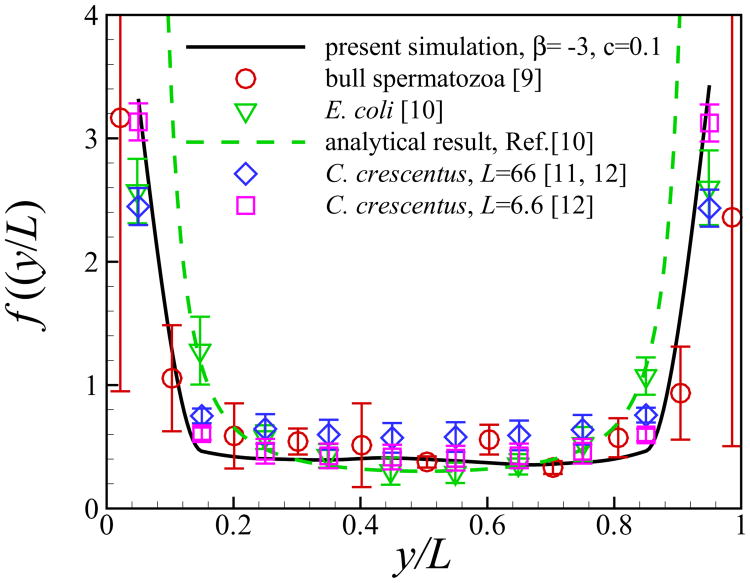
Fig. 11(a) shows the probability distribution function of the vertical position of squirmers. The squirmers are accumulated near the walls and the probability distribution function rapidly falls away from the walls. When close to the wall, pushers and pullers have stronger tendencies to accumulate near the wall compared to neutral squirmers. This result is predictable since the stresslet (strongest far-field interaction) is absent in the case of neutral squirmer [24]. At high concentrations, the peaks of f(y) near the two walls are lower than the cases of c = 0.1 because the layer of the squirmers close to the wall is nearly saturated and the concentration in the middle of the channel grows. Similar results have been reported in [49, 50]. In Fig. 12, we quantitatively compare our simulation results of pusher of β = −3 and c = 0.1 with published experimental/analytical results. The volume concentration of the cells in the experiments were reported in the range of c = 0.01–0.1 and the ratio between the channel width and the cell radius is around 40 for bull spermatozoa [9], 20-80 for E. coli [10], 66 for C. crescentus [11, 12] and 6.6 for C. crescentus [12], respectively. All the results show an increase in concentration of microorganisms near the wall, and the wall attraction is stronger for the smaller channel width. Our results show good agreements with the results of C. crescentus which is performed at a small channel width [12]. The analytical results solely based on the dipole interaction with the wall [10] overestimates the probability distribution of swimmers near the wall compared to the results of direct numerical simulation.
Fig. 12.
(Color online) Comparison of vertical distribution of microorganisms between present simulation results and previous experimental/analytical studies.
Fig. 11(b) shows the probability distribution function of the orientation angle of the swimmers f(α). A peak near α = −π/2 is observed for all the cases. For squirmers of β = 0 at c = 0.1, another peak occurs near α = 0. To better visualize the results, the probability distribution function of the orientation angle f(α) is plotted for the squirmers near the wall and in the bulk region in Figs. 11(c) and 11(d), respectively. The near-wall squirmers are strongly oriented normal to the wall (see Fig. 9). Interestingly for squirmers away from the wall, two different types of behavior are observed: for cases of β = 0 and 3 at c = 0.1, α is mostly between −π/4 and π/4 and there is a clear peak at α = 0; and for cases of β = −3, c = 0.1 and β = 0, c = 0.4, f(α) is almost uniformly distributed over −π/2 to π/2. From the results of a single squirmer in Fig. 4(b), after the initial wall contact, all the squirmers detach from the wall with the finial angle between −π/4 to π/4 (0.56, 0.41, and -0.24 for β = −3,0, and 3, respectively). We have also shown that the finial angles are independent of the initial impact angle of the squirmer if a close contact between the squirmer and the wall occurs. Therefore, when squirmers swim into the bulk region, their orientation angle is mainly between −π/4 and π/4. However, for cases of β = −3, c = 0.1 and β = 0, c = 0.4, squirmers collide with each other more frequently, which leads to a more uniform distribution in the orientation angle. As shown in Fig. 11(e), the distribution of vertical velocity component v dominates at 0, which also indicates the high percentage of the near-wall squirmers. Similar results can be also found in Fig. 11(f) for u and w components of velocity.
Previous studies have shown that the hydrodynamic interaction between squirmers generates large scale flows and leads to a collective motion, with a range and duration depending on the volume fraction and the swimming type β [36, 60]. The spatial correlation function g(r) can be used to quantify this interaction
| (14) |
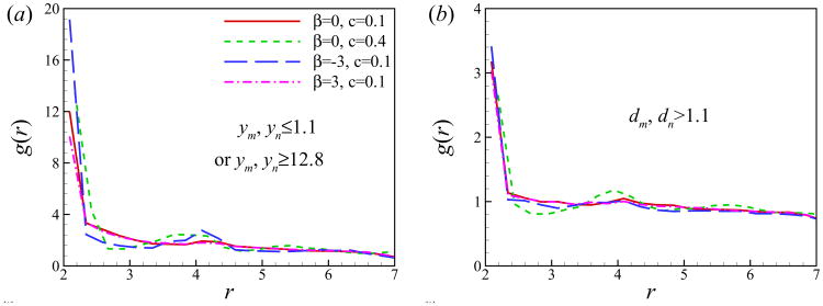
where rm,n is the distance between squirmers m and n, V(rm,n) = (4π/3)((rm,n + Δr/2)3 − (rm,n − Δr/2)3) is the volume of spherical shell of radius rm,n and thickness Δr. Figs. 13 (a) and (b) show the pair distribution function for squirmers close to the wall and in the bulk region, respectively. For the squirmers near the wall, g(r) peaks at around r = 2 and 4, referring to the cluster formation of squirmers in the near-wall region. The curve of β = −3 has the highest peak at r ≃ 2, meaning that a larger number of pushers are in close contact (see Fig. 9(c)). On the contrary, pullers are more scattered. This can be explained by the side-by-side interactions between two pushers, which is an attractive force, and two pullers, which is a repulsive force [2]. All curves have similar distributions for the bulk squirmers, the pair distribution function has a peak near r = 2 corresponding to the squirmers in close contact. Similar results were reported for the suspension of passive particles [61], bubbles [62], and two-dimensional swimming particles [60] in an unbounded domain.
Fig. 13.
(Color online) Pair distribution function for the squirmers (a) close to either walls or (b) in the bulk region.
The flow field near the bottom wall (y = 0) generated by pushers (β = −3) and pullers (β = 3) is plotted in Fig. 14. The contourplot of the vertical velocity component v is shown in the plane of y = 2.5. For clarity, the squirmers above the plane is not shown here. Near-wall pushers accumulate near each other and form large scale coherent structures. Previous studies have shown that these coherent structures can increase the mass transport [41, 42]. On the contrary, near-wall pullers are more scattered due to the side-by-side repelling force between them.
Fig. 14.
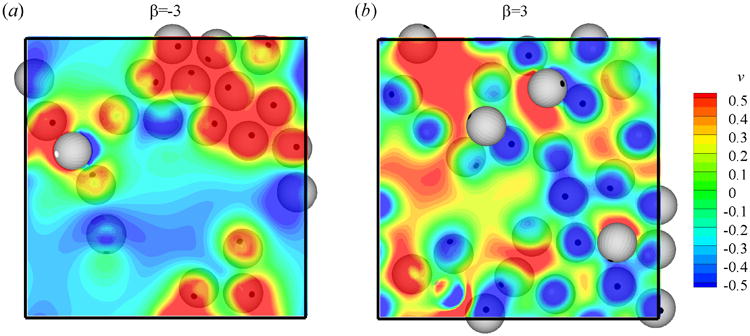
(Color online) Top view of the flow field near the bottom wall of a suspension of (a) pushers (β = −3) and (b) pullers (β = 3). Contourplots show the distribution of velocity component v on the plane of y = 2.5.
IV. Conclusion
We have studied the dynamics of a single and multiple low-Reynolds-number swimming organism(s) near a wall by conducting a three-dimensional direct numerical simulation. Each swimmer is modeled as a squirmer, which consists of a spherical body that propels itself by a tangential velocity distribution on its surface.
When a single squirmer is initially oriented towards the wall, three different modes are observed for Re = 1: (a) squirmers of β ≤ 1 escapes from the wall, (b) squirmers of 2 ≤ β ≤ 5 oscillate near the wall and eventually swim along the wall keeping a constant distance and orientation angle and (c) squirmers of β ≥ 7 bounce on the wall. At a smaller Reynolds number, Re = 0.1, the initial wall contact time is increased independent of the swimming type, but a weaker attraction towards the wall is observed for the puller. The dynamics of suspension of squirmers between two walls is also studied. Similar to the observation of previous experiments [9–12], we found that the squirmers are strongly attracted to the walls. At a relatively small concentration of c = 0.1, around 60 ∼ 80% of the squirmers are accumulated near the wall, the attraction of pushers and pullers is stronger than neutral squirmers. At a high concentration, c = 0.4, around 40% of the squirmers are near the wall. In the near-wall region, the squirmers mostly orient normal to the walls, while in the bulk region, the orientation angle of squirmers are more uniformly distributed or they orient in the direction parallel to the wall. The wall leads to the decrease of the average swimming speed of the squirmers. The pair distribution function shows that suspensions of pushers form large scale clusters near a wall, which is not the case for pullers.
It is interesting to extend the results of this paper by including higher-order squirming modes which will affect the near-wall motion of the squirmer. In our simulations, the squirmer model is used to reduce the complexities of real microorganisms. The first two squirming modes capture the most important features of pusher- and puller-type microswimmers. Previous experiments of E. Coli near a surface [10, 63] show that a stresslet and its image singularities, included to satisfy the no-slip boundary condition on the wall, describes the measured flow field around a bacterial cell near a wall with good accuracy. Since higher-order squirming modes will extensively expand the parameter space, our simulation as well as most of the previous studies [30–37] only considered the first two squirming modes.
Acknowledgments
This publication was made possible, in part, with support from NSF (Grant No. CBET-1150348-CAREER) and Indiana Clinical and Translational Sciences Institute Collaboration in Biomedical/Translational Research (CBR/CTR) Pilot Program Grants (Grant No. TR000006) from the National Institute of Health, National Center for Advancing Translational Sciences, Clinical and Translational Sciences Award.
V. Appendix
In addition to the validation test included in the main text, we provide two additional validation tests.
A. A squirmer colliding with a wall
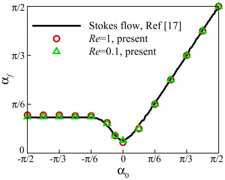
Here, we compare the results of our numerical code against the published results of Spagnolie and Lauga [24] for a neutral squirmer swimming near a wall. The computational domain is [−16,16] × [0, 25.6] × [−6.4, 6.4] with a uniform mesh size Δ = 0.1 and the time step is set to Δt = 1 × 10⁻³. The wall boundary is located at y = 0 and the squirmer is initially placed above the wall at h0 = 2. Fig. 15 shows the final steady angle of the squirmer of β = 0 with various initial angles α0. The results show good agreement with the simulation results of Spagnolie and Lauga [24] at Re = 0 using a boundary-integral method based on regularized Stokeslets.
Fig. 15.
(Color online) Comparison of the final angle of a neutral squirmer for various initial angles and a constant initial height of h0 = 2 with the results of [24].
B. A particle moving between two parallel walls
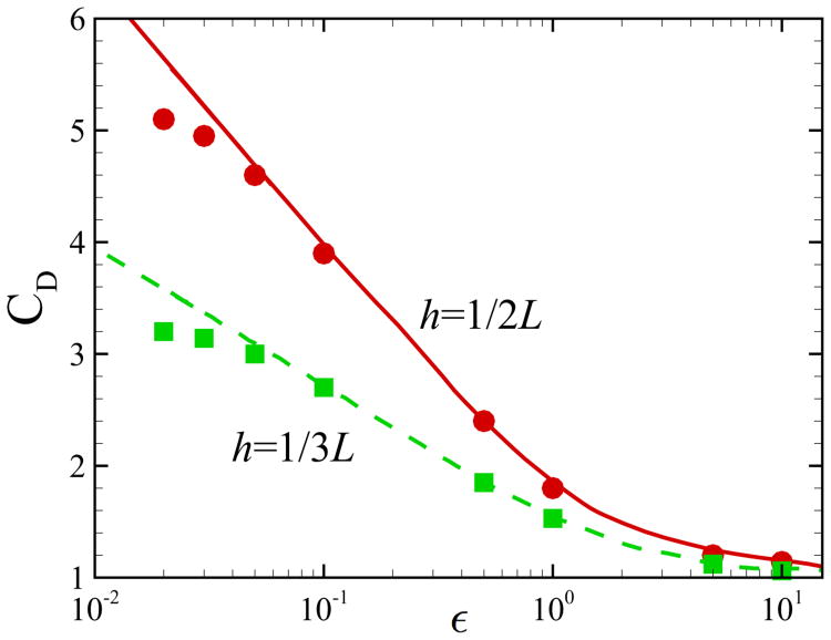
Here, we compare the results of our numerical code against the published results of Bhattacharya et al. [46] for an inert particle moving with velocity U along x direction between two parallel walls and evaluate the drag force acting on the particle for different values of distance from the lower wall. The particle is initially located at (0, h, 0). In order to facilitate the computation, we consider the frame of reference moving with the particle. In this frame, the particle is fixed and the walls, located at y = 0 and y = L, move with velocity U along x direction. Inlet velocity U is imposed at x = −50. Simulations are conducted in a rectangular domain of [−50, 50] × [0, L] × [−50, 50]. The time step is set to Δt = 1 × 10⁻⁵ and stretched grids are used where the mesh resolution around the particle is Δ = 0.1. The distance between the particle and the lower wall is defined as ε = h − 1 and the Reynolds number is set to Re = 0.01. We calculate the normalized drag force coefficient CD = FD/6π μUa, where FD is the drag force acting on the sphere. The comparison between our results and the semi-analytical results of Bhattacharya et al. [46] using a modified Stokesian dynamics method is shown in Fig. 16. Our results start to deviate from the results of Bhattacharya et al. [46] at ε ≃ 0.05, which corresponds to half a mesh size. Similar accuracy is also achieved in Lambert et al. [30] when simulating two spherical particles in shearing or squeezing motion.
Fig. 16.
(Color online) Comparison of the results for a single translating particle between two walls. Symbols: present numerical results at Re = 0.01; lines: simulation results of [46].
References
- 1.Harshey RM. Annu Rev Microbiol. 2003;57:249. doi: 10.1146/annurev.micro.57.030502.091014. [DOI] [PubMed] [Google Scholar]
- 2.Lauga E, Powers TR. Rep Prog Phys. 2009;72:096601. [Google Scholar]
- 3.Van Loosdrecht MCM, Lyklema J, Norde W, Zehnder AJB. Microbiol Rev. 1990;54:75. doi: 10.1128/mr.54.1.75-87.1990. [DOI] [PMC free article] [PubMed] [Google Scholar]
- 4.Suarez SS, Pacey AA. Human Reprod. 2006;12:23. doi: 10.1093/humupd/dmi047. Update. [DOI] [PubMed] [Google Scholar]
- 5.Katz DF. J Fluid Mech. 1974;64:33. [Google Scholar]
- 6.Katz D, Blake JR, Paverifontana S. J Fluid Mech. 1975;72:529. [Google Scholar]
- 7.Fauci LJ, McDonald A. Bull Math Biol. 1995;57:679. doi: 10.1007/BF02461846. [DOI] [PubMed] [Google Scholar]
- 8.Lauga E, DiLuzio WR, Whitesides GM, Stone HA. Biophys J. 2006;90:400. doi: 10.1529/biophysj.105.069401. [DOI] [PMC free article] [PubMed] [Google Scholar]
- 9.Rothschild L. Nature. 1963;198:1221. [Google Scholar]
- 10.Berke AP, Turner L, Berg HC, Lauga E. Phys Rev Lett. 2008;101:038102. doi: 10.1103/PhysRevLett.101.038102. [DOI] [PubMed] [Google Scholar]
- 11.Li G, Tang JX. Phys Rev Lett. 2009;103:078101. doi: 10.1103/PhysRevLett.103.078101. [DOI] [PMC free article] [PubMed] [Google Scholar]
- 12.Li G, Bensson J, Nisimova L, Munger D, Mahautmr P, Tang JX. Phys Rev E. 2011;84:041932. doi: 10.1103/PhysRevE.84.041932. [DOI] [PubMed] [Google Scholar]
- 13.Drescher K, Dunkel J, Cisneros LH, Ganguly S, Goldstein R. Phys Rev Lett. 2009;102:168101. doi: 10.1103/PhysRevLett.102.168101. [DOI] [PMC free article] [PubMed] [Google Scholar]
- 14.Hamel A, Fisch C, Combettes L, Dupuis-Williams P, Baroud CN. Proc Natl Acad Sci U S A. 2011;108:7290. doi: 10.1073/pnas.1016687108. [DOI] [PMC free article] [PubMed] [Google Scholar]
- 15.Jiang H, Kiørbeo T. J R Soc Interface. 2011;8:1090. doi: 10.1098/rsif.2010.0481. [DOI] [PMC free article] [PubMed] [Google Scholar]
- 16.Wang S, Ardekani AM. J Fluid Mech. 2012;702:286. [Google Scholar]
- 17.Wang S, Ardekani AM. Phys Fluids. 2012;24:101902. [Google Scholar]
- 18.Zilman G, Novak J, Benayahu Y. Mar Biol. 2008;154:1. [Google Scholar]
- 19.Zargar R, Najafi A, Miri M. Phys Rev E. 2009;80:026308. doi: 10.1103/PhysRevE.80.026308. [DOI] [PubMed] [Google Scholar]
- 20.Or Y, Murray RM. Phys Rev E. 2009;79:045302. doi: 10.1103/PhysRevE.79.045302. [DOI] [PubMed] [Google Scholar]
- 21.Crowdy DG, Or Y. Phys Rev E. 2010;81:036313. doi: 10.1103/PhysRevE.81.036313. [DOI] [PubMed] [Google Scholar]
- 22.Crowdy D, Samson O. J Fluid Mech. 2011;667:309. [Google Scholar]
- 23.Dunstan J, Miño G, Clement E, Soto R. Phys Fluids. 2012;24:011901. [Google Scholar]
- 24.Spagnolie SE, Lauga E. J Fluid Mech. 2012;700:105. [Google Scholar]
- 25.Lighthill MJ. Comm Pure Appl Math. 1952;5:109. [Google Scholar]
- 26.Blake JR. J Fluid Mech. 1971;46:199. [Google Scholar]
- 27.Shapere A, Wilczek F. J Fluid Mech. 1989;198:557. [Google Scholar]
- 28.Keller SR, Wu TY. J Fluid Mech. 1977;80:259. [Google Scholar]
- 29.Felderhof BU, Jones RB. Physica A. 1994;202:119. [Google Scholar]
- 30.Lambert RA, Picano F, Breugem W, Brandt L. J Fluid Mech. 2013;733:528. [Google Scholar]
- 31.Doostmohammadi A, Stocker R, Ardekani AM. Proc Natl Acad Sci U S A. 2012;109:3856. doi: 10.1073/pnas.1116210109. [DOI] [PMC free article] [PubMed] [Google Scholar]
- 32.Zhu L, Lauga E, Brandt L. J Fluid Mech. 2013;726:285. [Google Scholar]
- 33.Ishikawa T, Simmonds MP, Pedley TJ. J Fluid Mech. 2006;568:119. [Google Scholar]
- 34.Ishikawa T, Pedley TJ. J Fluid Mech. 2007;588:399. [Google Scholar]
- 35.Ishikawa T, Pedley TJ. J Fluid Mech. 2007;588:437. [Google Scholar]
- 36.Ishikawa T, Locsei JT, Pedley TJ. J Fluid Mech. 2008;615:401. [Google Scholar]
- 37.Ishikawa T. J Fluid Mech. 2012;705:98. [Google Scholar]
- 38.Magar V, Pedley TJ. J Fluid Mech. 2005;539:93. [Google Scholar]
- 39.Lin Z, Thiffeault JL, Childress S. J Fluid Mech. 2011;669:167. [Google Scholar]
- 40.Koch DL, Subramanian G. Annu Rev Fluid Mech. 2010;43:637. [Google Scholar]
- 41.Sokolov A, Goldstein RE, Feldchtein FI, Aranson IS. Phys Rev E. 2009;80:031903. doi: 10.1103/PhysRevE.80.031903. [DOI] [PubMed] [Google Scholar]
- 42.Wu X, Libchaber A. Phys Rev Lett. 2000;84:3017. doi: 10.1103/PhysRevLett.84.3017. [DOI] [PubMed] [Google Scholar]
- 43.Cichocki B, Jones RB, Kutteh R, Wajnryb E. J Chem Phys. 2000;112:2548. [Google Scholar]
- 44.Pesché R, Nägele G. Phys Rev E. 2000;62:5432. doi: 10.1103/physreve.62.5432. [DOI] [PubMed] [Google Scholar]
- 45.Bhattacharya S, Bławzdziewicz J, Wajnryb E. Physica A. 2005;356:294. [Google Scholar]
- 46.Bhattacharya S, Bławzdziewicz J, Wajnryb E. J Fluid Mech. 2005;541:263. [Google Scholar]
- 47.Underhill PT, Hernandez-Ortiz JP, Graham MD. Phys Rev Lett. 2008;100:248101. doi: 10.1103/PhysRevLett.100.248101. [DOI] [PubMed] [Google Scholar]
- 48.Underhill PT, Graham MD. Phys Fluids. 2011;23:121902. [Google Scholar]
- 49.Hernández-Ortiz JP, Stoltz CG, Graham MD. Phys Rev Lett. 2005;95:204501. doi: 10.1103/PhysRevLett.95.204501. [DOI] [PubMed] [Google Scholar]
- 50.Hernández-Ortiz JP, Underhill PT, Graham MD. J Phys: Condens Matter. 2009;21:204107. doi: 10.1088/0953-8984/21/20/204107. [DOI] [PubMed] [Google Scholar]
- 51.Wensink HH, Löwen H. Phys Rev E. 2008;78:031409. doi: 10.1103/PhysRevE.78.031409. [DOI] [PubMed] [Google Scholar]
- 52.Sharma A, Patankar NA. J Comput Phys. 2005;205:439. [Google Scholar]
- 53.Ardekani AA, Dabiri S, Rangel RH. J Comput Phys. 2008;227:10094. [Google Scholar]
- 54.Ardekani AM, Rangel RH. J Fluid Mech. 2008;596:437. [Google Scholar]
- 55.Doostmohanmmadi A, Dabiri S, Ardekani AM. J Fluid Mech. 2014;750:5. [Google Scholar]
- 56.Ardekani AM, Dabiri S, Rangel RH. Phys Fluids. 2009;21:093302. [Google Scholar]
- 57.Doostmohammadi A, Ardekani AM. Phys Rev E. 2013;88:023029. doi: 10.1103/PhysRevE.88.023029. [DOI] [PubMed] [Google Scholar]
- 58.Khair AS, Chisholm NG. Phys Fluids. 2014;26:011902. [Google Scholar]
- 59.Glowinski R, Pan TW, Hesla TI, Joseph DD, Periaux J. J Comput Phys. 2001;169:363. [Google Scholar]
- 60.Mehandia V, Nott PR. J Fluid Mech. 2008;595:239. [Google Scholar]
- 61.Sierou A, Brady JF. J Rheol. 2002;46:1031. [Google Scholar]
- 62.Bunner B, Tryggvason G. J Fluid Mech. 2002;466:17. [Google Scholar]
- 63.Drescher K, Leptos K, Tuval I, Ishikawa T, Pedley T, Goldstein R. Proc Natl Acad Sci U S A. 2011;108:10940. [Google Scholar]


