Abstract
Organic semiconductors have great potential for producing hydrogen in a durable and economically viable manner, as they rely on readily available materials and can be solution-processed over large areas. With the objective of building efficient hybrid organic-inorganic photo-electrochemical cells, we combined a noble metal-free and solution-processable catalyst for proton reduction, MoS3, and a poly-(3-hexylthiophene):phenyl-C61-butyric acid methyl ester (P3HT:PCBM) bulk heterojunction (BHJ). Different interfacial layers were investigated to improve the charge transfer between P3HT:PCBM and MoS3. Metallic Al\Ti interfacial layers led to an increase of the photocurrent up to 8 mA cm−2 at reversible hydrogen electrode (RHE) potential with a 0.6 V anodic shift of the HER onset potential, a value close to the open circuit potential of the P3HT:PCBM solar cell. A 50 nm thick C60 layer also works as interfacial layer, with current density reaching 1 mA cm−2 at RHE potential. Moreover, two recently highlighted1 figures-of-merit, measuring the ratio of power saved, Φsaved,ideal and Φsaved,NPAC, were evaluated and discussed to compare the performances of various photocathodes assessed in a three-electrode configuration. Φsaved,ideal and Φsaved,NPAC use the RHE and a non-photoactive electrode with identical catalyst as dark electrode, respectively. They provide different information especially for the differentiation of the role of the photogenerating layer and the role of the catalyst. Best results were obtained with the Al\Ti metallic interlayer, with Φsaved,ideal and Φsaved,NPAC reaching 0.64 % and 2.05 % respectively.
Keywords: organic photovoltaics, photocathode, hydrogen evolution reaction, organic semiconductor, photocatalysis, molybdenum sulfide
1. Introduction
Solar-to-chemical energy conversion is an attractive solution for the wide-scale storage and on-demand use of solar energy. Directly producing hydrogen from solar energy and water additionally participates in the building of a carbon-neutral economy. Though benchmarking with fossil resources based technologies is still challenging, the search for cost-effective and efficient photocatalytic systems is getting more and more important.
Photoelectrochemical (PEC) cells performing solar water splitting are widely reported in the literature, both in academic journals2,3 and in patents.4 They can have many different configurations depending on the absorber, catalysts and co-catalysts, number of photoelectrodes, buried junctions, etc.2,5 An ideal PEC device should meet several criteria:6 optical absorption in the IR-visible range (corresponding to 80 % of the solar flux), resistance to corrosion in aqueous electrolytes, solar-to-hydrogen conversion yield (STH) higher than 10 %, competitive cost on an energy-equivalent basis, absence of toxic effects, simple fabrication processes and great availability of materials.7 Performant devices exist, such as the AlGaAs/Si/RuO2/Pt cell, reaching over 18 % of solar to chemical energy conversion.8 To reduce the cost linked to the use of expensive and rare materials, multi-junction silicon solar cells were used with earth-abundant catalysts by Rocheleau,9 Suzuki10 and Nocera,11 reaching 7.8 % (wired configuration), 2.5 % (wireless configuration) and 4.7 % (wired configuration, 2.5 % in wireless configuration) respectively. Besides, cost-effective crystalline metal oxide semiconductors such as Cu2O12,13 or BiVO414,15 have been used to build PEC cells other than the above-mentioned systems, with promising STH efficiencies.
Organic semiconductors (OSC) such as conducting polymers or fullerene derivatives are promising in the field of photovoltaic cells, which now display over 10 % power conversion efficiency (PCE)16 using abundant materials and low-cost processes. An advantage of using OSC in PEC is that thanks to chemical synthesis, a wide variety of materials can be obtained with different energy levels which can be tuned to the redox potentials required by water splitting catalysts to operate. OSC have thus been used for solar water splitting devices in different configurations. In a PV-electrolyzer configuration, an all-solution processed triple junction polymer solar cell with an open-circuit potential (VOC) of 2.33 V was connected to an electrolyzer to perform water splitting.17 In a distinct approach, integrated photocathodes were built based on OSC such as polyaniline, polypyrrole, poly-(3-methylthiophene) or poly-(3-hexylthiophene) (P3HT), but only a few μA cm−2 photocurrent were obtained in aqueous environment and the production of hydrogen was not always evidenced.18-22 Then, adding a fullerene acceptor to P3HT to form a P3HT:PCBM bulk heterojunction, this photocathode was used with NaCl as sacrificial donor, in a two electrode configuration and still without catalyst, and reached a peak current of 100 nA cm−2.6 To enhance proton reduction at the photocathode surface, a Pt catalyst was added at the top of an evaporated small molecule (phthalocyanine/fullerene) p/n planar junction and generated 800 μA cm−2 photocurrent corresponding to H2 evolution from aqueous solution.23 Recently, molybdenum sulfide (MoSx) was used as both acceptor and catalyst in a nanocomposite polypyrrole-Ru/MoSx photocathode and delivered around 40 μA cm−2 at RHE potential.24 In an earlier work, we studied a photocathode based on the photosensitization of a non-precious catalyst, MoS3, by a P3HT:PCBM bulk heterojunction (BHJ) in aqueous media.25 MoS3 was chosen as it is a noble metal-free hydrogen evolution catalyst (with an overpotential of 150 mV26) and it can be solution-processed directly onto thin OSC films without thermal treatment, which could be detrimental to the organic layer. In this way, MoS3 photo-produced hydrogen with a current density of 180 μA cm−2 at the reversible hydrogen electrode (RHE) potential. Another PEC cell based on P3HT:PCBM photocathode was recently reported to produce hydrogen from HCl-acidified acetonitrile solution with a cobaloxime catalyst, with 1 mA cm−2 photocurrent density.27
In this work, we decided to investigate the possibility to enhance the performance in aqueous media of our system25 through the introduction of a dense and conductive layer between the P3HT:PCBM layer and the MoS3 catalyst. We report here on the results obtained with two different interfacial layers: (1) a metallic material used to improve electronic collection and electronic transfer to the catalyst, and (2) a nanocarbon layer used as fully organic interfacial layer. These two interfacial layers showed improved charge transfer compared to the initial cells without interfacial layers, as evidenced by the ratio of power saved under operation quantified through the determination of the ratiometric power-saved figures-of-merit Φsaved,ideal and Φsaved,NPAC, as recently proposed par Lewis and coworkers.1
2. Experimental
2.1. Chemicals and reagents
All manipulations were carried out under inert Ar atmosphere in a glovebox unless otherwise mentioned. PEDOT:PSS (AI 4083 for spin-coated devices) and P3HT (M104, RR = 96.3 %) were purchased from Ossila. PCBM was purchased from Solenn BV. ITO-coated glass substrates (XY20s) were purchased from Xinyan Technology Ltd. The MoS3 nanoparticles suspension was prepared according to the literature28 and a detailed procedure is given in the Supporting Information section.
2.2. Fabrication of the photocathodes
ITO\PEDOT:PSS\P3HT:PCBM
The P3HT:PCBM solution was prepared by dissolving 25 mg of P3HT and 25 mg of PCBM in 1 mL of anhydrous ortho-dichlorobenzene in the glovebox. The solution was stirred at 50 °C for 2 hours and then at room temperature overnight. PEDOT:PSS was filtered with a PVDF filter (0.45 μm) and spin-coated on cleaned (see SI) ITO-coated glass substrate in the air (speed: 3000 rpm / ramp: 5 s / dwelling time: 30 s followed by 5000 rpm / 5 s / 30 s), resulting in a 40 nm thick layer (measured by profilometry). After thermal treatment in the air for 10 minutes at 150 °C, the substrate was quickly transferred in the glovebox. The P3HT:PCBM blend was filtered with a 0.45 μm PVDF filter and spin-coated on top of the PEDOT:PSS layer (1500 rpm / 5 s / 60 s). The thickness of the P3HT:PCBM layer was estimated by profilometry at 170 ± 10 nm. Annealing was performed at this stage depending on the deposition of the following interfacial layer.
ITO\PEDOT:PSS\P3HT:PCBM\LiF\Al\Ti\MoS3
The former electrode was annealed at 140 °C for 5 min in the glovebox and 1.2 nm of LiF followed by 100 nm of Al were deposited under vacuum (< 10−6 mbar, 0.4 Å s−1 for LiF and 0.15 nm s−1 for Al) in a Joule evaporator. 30 to 50 nm of Ti were then evaporated (0.5 Å s−1). The electrode temperature was close to room temperature and in any case below the annealing temperature used to stabilize the bulk heterojunction. In the glovebox, the MoS3 solution was spin-coated at 2000 rpm / 5 s / 30 s followed by 20 s at 70 °C to dry the remaining solvent. The thickness of the MoS3 film was 30 nm (measured by profilometry). ITO\PEDOT:PSS\P3HT:PCBM\Ti\MoS3 and ITO\PEDOT:PSS\P3HT:PCBM\LiF\Al\MoS3 were prepared the same way, with only the evaporation of Ti or of LiF\Al respectively. As a reference sample, ITO\PEDOT:PSS\P3HT:PCBM\LiF\Al\Ti\Pt/C photocathodes were made with a Pt/C ink. The ink was prepared by sonicating (1 h) 10 mg of commercial Pt/C (Alfa Aesar, 40 wt.% of Pt, HiSPEC 4000™) in 400 μL of ethanol, 100 μL of deionized water and 65 μL of a Nafion dispersion (D-520, 5 % w/w in water and isopropanol, from Alfa Aesar). The Pt/C ink was spin-coated under the same conditions as the MoS3 suspension.
ITO\PEDOT:PSS\P3HT:PCBM\C60\MoS3
P3HT:PCBM deposited on ITO\PEDOT:PSS was annealed at 140 °C for 5 min in the glovebox. C60 (50 nm) was evaporated in a Joule evaporator under vacuum (< 10−6 mbar, 0.5 Å s−1, 500 – 530 °C). The MoS3 catalytic layer was sprayed on top of the heated (85 °C, cf. SI) solar cell in the air, and the electrode was quickly retransferred into the glovebox.
2.3. Electro- and photo-electrochemical characterization
Electrochemical measurements were recorded using a BioLogic Model VSP 0254 potentiostat. A three-electrode configuration was used. For polarization and electrolysis measurements, a glassy carbon plate and an Ag/AgCl (KCl 3.5 M) electrode were used as the auxiliary electrode and the reference electrode, respectively. Potentials are quoted against the Reversible Hydrogen Electrode. Details of the calibration method for the reference electrode are given in SI.
For the photocatalytic tests, the photocathode was not entirely plunged into the electrolyte (0.5 M H2SO4): only the MoS3 side was put in contact with the electrolyte thanks to a rubber seal with a hole corresponding to the electrochemical area. The glass\ITO side was illuminated with a lamp, as presented in Fig. S1. The samples were illuminated with a 200 W mercury-xenon lamp operated at 106 W coupled with a Spectra-Physics 59472 UV cut-off filter (λ > 440 nm) and a circular mask. Irradiance at the substrate surface was measured to ~ 100 mW cm−2 thanks to a Coherent PowerMax-USB PM150-50C Power Sensor.
2.4. Other methods of characterization
The current–voltage characteristics of organic photovoltaic cells were independently measured with a Keithley 2635 system Source Meter under nitrogen atmosphere. They were deposited onto an ITO-coated substrate with an etched side for the cathodic contact. A LiF\Al cathode (0.28 cm2) was deposited under vacuum in a Joule evaporator (< 10−6 mbar, 0.4 Å s−1 for 1.2 nm LiF and 0.15 nm s−1 for 100 nm Al). Solar cell performances were characterized under light intensity of AM 1.5 illumination with an Atlas Solar Constant 575PV simulator. The samples were illuminated through the glass substrate.
3. Results and discussion
The effect of interlayers between the MoS3 catalyst and the P3HT:PCBM BHJ on the photocatalytic performance is investigated by studying the photocurrent and photovoltage of the different photocathodes. They are also compared with the electrocatalytic activity of the bare catalyst, MoS3, which is an inorganic noble metal-free catalyst for the hydrogen evolution reaction (HER), with 150 mV onset overpotential.26
3.1. Increase of the electronic transfer at the P3HT:PCBM – MoS3 interface with metallic interlayers
In order to improve the current density previously obtained with ITO\PEDOT:PSS\P3HT:PCBM\MoS3 in aqueous electrolyte,25 we decided to use a LiF\Al layer intercalated between P3HT:PCBM and MoS3. LiF\Al is widely used as a cathode material for organic solar cells, as it has a suitable work function which efficiently collects the electrons from the fullerene derivative acceptor. It consists of a thin LiF layer (1.2 nm) and a metallic aluminum layer (typically 100 nm) evaporated under vacuum onto the P3HT:PCBM bulk heterojunction. When such a solar cell is characterized, the voltage is applied between this Al cathode and the ITO anode. The constructions with ITO\PEDOT:PSS\P3HT:PCBM\LiF\Al\MoS3 architectures did however not exhibit promising properties since the aluminum layer got rapidly oxidized in the acidic electrolyte despite the presence of the spin-coated catalyst overlayer. Such an oxidative process was evidenced by the observation of anodic dark currents, which could not be completely reversed even under illumination (Fig. S2). In other words, the cathodic photocurrent corresponding to H2 evolution was always found lower than the oxidation dark current. Using a mixed MoS3:TiO2 catalyst, as described in our previous work, thicker catalyst films were deposited to achieve better protection of the aluminum layer. In that case, the photocurrent (Fig. S2) (about 0.8 mA cm−2) was significantly higher than the dark oxidation current (about 0.2 mA cm−2). Nevertheless, the performances were not stable with time and continuous operation resulted in a concomitant decrease of the photocurrent and increase of the dark current as the aluminum layer progressively dissolved in the acidic media.
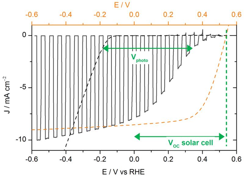
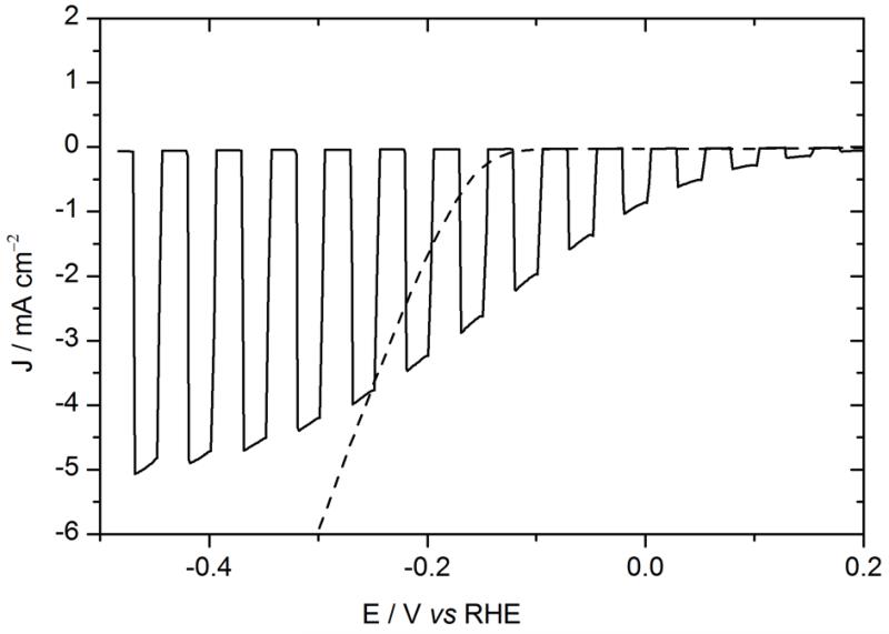
To protect the Al layer, a metallic titanium layer was evaporated on top of Al. Ti had already been used as a protective layer in a Si-based photocathode.29-32 Organic photocathodes with a titanium overlayer were fabricated starting from ITO\PEDOT:PSS\P3HT:PCBM\LiF\Al by depositing a 30 nm thick Ti layer in a Joule evaporator. The voltammogram recorded in 0.5 M H2SO4 electrolyte under chopped illumination is presented in Fig. 1, with the J-V curve of the equivalent solar cell for comparison.
Figure. 1.
Voltammogram recorded at 50 mV s−1 in 0.5 M H2SO4 with chopped visible light for an ITO\PEDOT:PSS\P3HT:PCBM\LiF\Al\Ti\MoS3 photocathode (black line, electrode area 0.32 cm2), and recorded at 5 mV s−1 in 0.5 M H2SO4 for an ITO\MoS3 cathode (black dashed line, electrode area 0.28 cm2). Potentials are referred to the RHE (bottom axis). The current-voltage curve of an ITO\PEDOT:PSS\P3HT:PCBM\LiF\Al solar cell (orange dashed line, top axis) is shown for comparison.
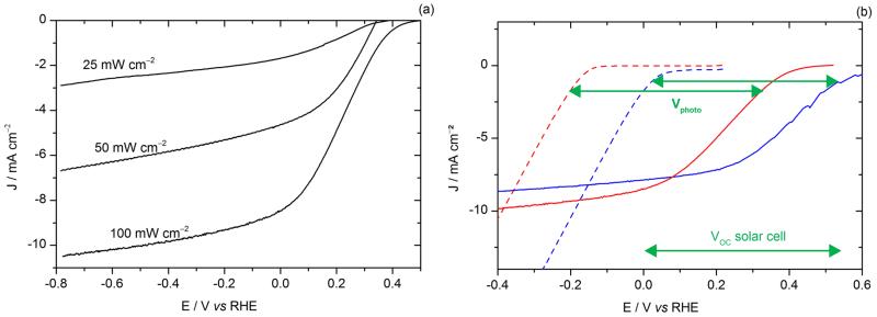
The performances of the photoelectrodes were significantly improved compared to our previous devices,25 with a photocurrent value of 8 mA cm−2 at 0 V vs RHE and reaching 10 mA cm−2 at more cathodic potentials. The onset of light-driven HER (values were taken at 0.1 mA cm−2) was observed at + 0.48 V vs RHE. Dark HER onset was found at −0.15 V vs RHE (black dashed line in Fig. 1), as expected for MoS3 under these conditions.28 The light-driven anodic shift of the HER onset potential, called photovoltage Vphoto in the following, was thus found equal to 0.63 V, close to the open-circuit voltage (VOC) of the organic solar cell (approximately 0.6 V). For illuminated photoelectrodes, current limitation occurs at quite negative potentials, which contrasts with the behavior of electrodes based on MoS3 electrocatalyst alone, which I-V curve continues to increase when decreasing the potential. This plateau (typically 10 mA cm−2) thus does not correspond to a diffusion-limited current. It likely originates from saturation of the solar cell as observed in typical current-voltage solar cell characteristics shown in Fig. 1. To verify this hypothesis, the power of the light source was changed. As shown in Fig. 2a, the saturation current changed accordingly. This confirms that the photocurrent value at low potential is limited by the photocurrent produced by the organic solar cell. Moreover, in the range of 0 to 0.5 V, the I-V curve of the photocathode was shifted by approximately 150 mV compared to the solar cell. This value seems to correspond to the overpotential requirement of the MoS3 catalyst. In order to further investigate this matter of fact, Fig. 2b shows the electro- and photoelectro-chemical HER activity of the unsensitized and OSC-sensitized MoS3 and Pt/C catalysts. Similarly to MoS3, the voltammogram of the illuminated ITO\PEDOT:PSS\P3HT:PCBM\LiF\Al\Ti\Pt/C photocathode was anodically shifted by a photovoltage close to the VOC of the solar cell (i.e. approximately 0.6 V) as compared to the voltammogram of the ITO\Pt/C cathode. The difference of onset potentials of both MoS3 and Pt catalysts was reflected in the difference of onset potentials of the two photocathodes. Fig. 2a and 2b thus shows that both photocurrent and photovoltage are optimal with the LiF\Al\Ti interlayer.
Figure. 2.
(a) Voltammograms recorded at 50 mV s−1 in 0.5 M H2SO4 with visible light illumination for a ITO\PEDOT:PSS\P3HT:PCBM\LiF\Al\Ti\MoS3 photocathode. The power of the light source was changed from ~ 100 mW cm−2 to ~ 25 mW cm−2. New photocathodes were taken for each test with a different power. Electrode area: 0.32 cm2. (b) Voltammogram recorded at 5 mV s−1 in 0.5 M H2SO4 for an ITO\MoS3 cathode (red dotted line) and an ITO\Pt/C cathode (blue dotted line) and at 50 mV s−1 with visible light illumination (100 mW cm−2) for an ITO\PEDOT:PSS\P3HT:PCBM\LiF\Al\Ti\MoS3 photocathode (red line), and an ITO\PEDOT:PSS\P3HT:PCBM\LiF\Al\Ti\Pt/C photocathode (blue line).
Despite the satisfying performance of the photocathodes, the photo-current decreased under operation (Fig. S3). This was attributed to the fact that the electrolyte could reach the aluminum layer through the Ti layer, resulting in the lift-off of the LiF\Al\Ti\MoS3 metallic layer, as observed by during the experiment. To avoid this phenomenon, photocathodes were made without the LiF/Al layer.
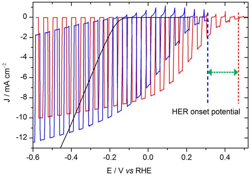
As shown in Fig. 3, the photocurrent displayed by the photocathode without LiF\Al (blue curve) was similar in intensity to that measured on the photocathode with LiF\Al\Ti. However the HER onset of the new photocathode was 150 mV more negative than the former one containing the LiF/Al layer. Actually the photovoltage provided by the solar cell is limited to 0.45 V (from −0.15 to +0.32 V vs RHE), compared to 0.6 V with LiF\Al\Ti. The lower photovoltage obtained without the LiF/Al layer can be attributed to the difference in the metals work functions (Fig. S4), which changes the electron injection barrier.
Figure. 3.
Voltammograms recorded at 50 mV s−1 in 0.5 M H2SO4 with chopped visible light. Red: ITO\PEDOT:PSS\P3HT:PCBM\LiF\Al\Ti\MoS3 photocathode (electrode area: 0.32 cm2); blue: ITO\PEDOT:PSS\P3HT:PCBM\Ti\MoS3 (0.28 cm2). The green arrow represents the shift of the HER onset potential of 150 mV.
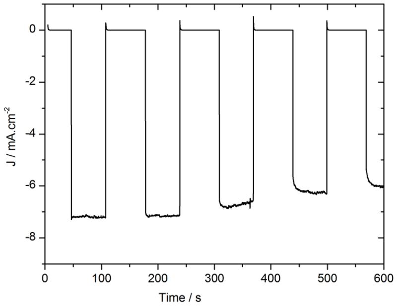
Stability measurements were then performed with chopped light at 0 V vs RHE. The results are presented in Fig. 4. The use of titanium as the sole interfacial layer clearly increased the stability under operation, with a loss of only 12% of the photocurrent over 10 min while the same photocathode with a LiF/Al/Ti interfacial layer was found to lose 45% of its performance under similar conditions (Fig S3). Moreover, after one hour, the titanium layer was not peeled off as the LiF/Al/Ti layer was. Thus, devices made without an aluminum layer were found significantly more stable.
Figure. 4.
Chronoamperometry at 0 V vs RHE in 0.5 M H2SO4 with chopped visible light for an ITO\PEDOT:PSS\P3HT:PCBM\Ti\MoS3 photocathode (black). Electrode area: 0.28 cm2.
To summarize, the use of metallic layers dramatically increased the efficiencies of the photocathodes compared to the first photocathodes that we reported which displayed photocurrent densities limited to 180 μA cm−2.25 These interfacial layers bury the P3HT:PCBM layer and electronically separate the catalyst/electrolyte interface and the photovoltaic cell. The p/n junction providing the photovoltage and driving force for HER is therefore not directly related to the difference between the redox potential of interest (H+/H2) and the conduction band edge position of the acceptor material (here PCBM). This removes the constraint of their alignment33 and also explains why the I-V curves obtained with these photocathodes are shaped like the I-V curves of the solar cells: all photogenerated electrons are collected by the metallic layer and then transferred to MoS3 for catalysis. As no direct liquid-semiconductor junction is formed, these devices can be identified as part of a PV-biased electrosynthetic cell,34 which is bringing the device a step away from the direct sensitization of a catalyst, that is, a step closer to a PV-electrolyzer.5 Finding chemically resistant, conductive and water-tight materials is still a challenging task, but metallic titanium is close to meeting all the criteria. Indeed, contrary to aluminum, it does not dissolve in acidic water, and is conductive. However, in terms of photovoltage, the use of a Ti interfacial layer alone shifts the J-V curve 150 mV more negative than with a combined Ti/Al layer. Then, we decided to test a fully organic interfacial layer by evaporating C60, a typical n-type organic semiconductor typically used in OPV cells.
3.2. Organic C60 interfacial layer
C60 is an organic molecule with a work function located between PCBM and MoS3, which makes it suitable as interfacial material for transferring the photogenerated electrons to MoS3. Deposition of thin layers is well-controlled with the use of vacuum evaporation. 50 nm of C60 were evaporated on P3HT:PCBM and the MoS3 suspension was then sprayed onto the C60. The voltammogram recorded under chopped light is presented in Fig. 5.
Figure. 5.
Voltammogram recorded at 50 mV s−1 in 0.5 M H2SO4 with chopped visible light for an ITO\PEDOT:PSS\P3HT:PCBM\C60\MoS3 photocathode (electrode area: 0.06 cm2). The polarization curve of ITO\MoS3 recorded at 5 mV s−1 is shown for comparison (dashed line, electrode area: 0.28 cm2).
Compared to our first photocathodes (without any interfacial layers, reaching 180 μA cm−2),25 the saturation photocurrent density and photovoltage are greatly enhanced. The photocurrent for ITO\PEDOT:PSS\P3HT:PCBM\C60\MoS3 photocathode is about 1 mA cm−2 at 0 V vs RHE (black line in Fig. 5) without any metallic interlayer. Again, the onset potential of the HER is shifted in the anodic direction from −0.15 V vs RHE (MoS3 in the dark) to +0.18 V vs RHE (light-driven HER), i.e. the photosensitizer provides a photovoltage of 0.33 V under operating conditions. The I-V curves of the ITO\PEDOT:PSS\P3HT:PCBM\C60\LiF\Al solid-state solar cell (Fig. S5) and of the corresponding ITO\PEDOT:PSS\P3HT:PCBM\C60\MoS3 photocathode are differing from each other more than the ITO\PEDOT:PSS:\P3HT:PCBM\LiF\Al solid-state solar cell and the corresponding ITO\PEDOT:PSS\P3HT:PCBM\LiF\Al\Ti\MoS3 photocathode (Fig. 1). Indeed, the current density of the photocathode with C60 does not reach the saturation obtained in the corresponding solar cell, while this saturation is reached for the photocathode with the LiF\Al\Ti interfacial layer. This could arise from a higher resistance in electronic transfer from C60 to MoS3 than from Al\Ti to MoS3, but also from the fact that the ITO\PEDOT:PSS\P3HT:PCBM\C60\MoS3 photocathode does not benefit from the reflectivity of the metallic layer of the ITO\PEDOT:PSS\P3HT:PCBM\LiF\Al\Ti\MoS3 photocathode, which enhances the photocurrent density. Moreover, both VOC and JSC of the solid-state ITO\PEDOT:PSS\P3HT:PCBM\C60\LiF\Al solar cell decreased compared to the ITO\PEDOT:PSS\P3HT:PCBM\LiF\Al solar cell (Fig. S6), possibly because of resistive losses due to the limited C60 conductivity of about 10−7 S cm−1.35
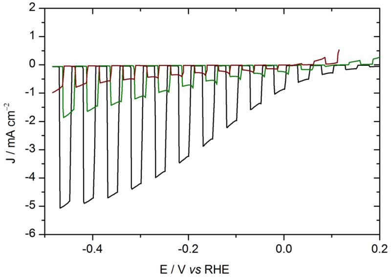
The hydrophobic nature of C6036 was expected to ensure better stability of the underlying P3HT:PCBM layer by preventing water from reaching it. However Fig. 6 shows that the photocathodes based on C60 interlayers degrade rapidly. The second scan already shows both a decrease of the photocurrent and a shift of the onset HER potential under irradiation towards more negative potentials, finally stabilizing near the equilibrium potential.
Figure. 6.
Voltammograms recorded at 50 mV s−1 in 0.5 M H2SO4 with chopped visible light for the same ITO\PEDOT:PSS\P3HT:PCBM\C60\MoS3 photocathode. Black: 1st cycle (same as Fig. 5); green: 2nd cycle; brown: 3rd cycle. Electrode area: 0.06 cm2. The oxidation current appearing at anodic potentials was also appearing in configurations without C60: thus, the oxidation current was not attributed to a possible reaction or degradation of C60 but more probably to the absence of equilibration time between the measurements.
These results are consistent with the previous results regarding the effect of a layer burying the P3HT:PCBM BHJ in the whole architecture and suppressing the semi-conductor/electrolyte interface. During the first cycle, the C60 layer does not contain water and partly separates the P3HT:PCBM material from the electrolyte. In the following cycles, the water progressively diffuses into the C60 layer and progressively reaches the P3HT:PCBM, as if there was no more interfacial layer protecting the device, explaining the shift in the onset HER potential as well as the decrease of photocurrent. The C60 layer increases the photocurrent density at RHE potential to 1 mA cm−2 without any metallic layer. We are now investigating the possibility of depositing more stable C60 derivatives using wet deposition processes.
In order to further investigate the impact of the interlayer on the photocathode performances we have carefully analyzed the results by means of two figures-of-merit measuring the amount of power saved by the electrode under operation.
3.3. Comparison of the photocathodes performance
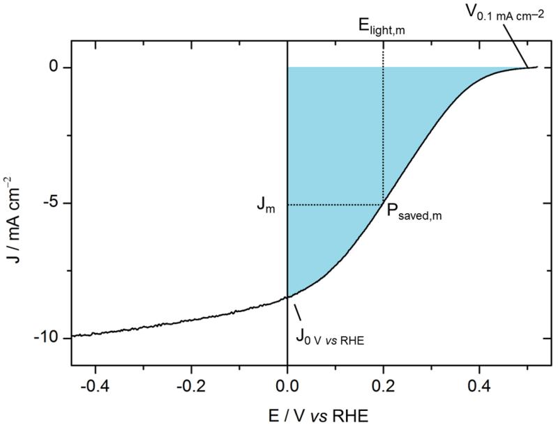
The ratiometric power-saved figure-of-merit Φsaved,ideal (Equ. (1)) relative to RHE, i.e. an ideally non-polarizable dark electrode for the same reaction, provides information on the ability of a photocathode to achieve hydrogen evolution at potentials more positive than the thermodynamic potential of H+/H2. Unlike the solar-to-hydrogen (STH) efficiency, which applies for devices achieving overall water splitting assayed in a two-electrode configuration1,2 (see SI for details), the ratiometric power saved figure-of-merit Φsaved,ideal measures the performance of a single photoelectrode tested under illumination in a three-electrode configuration and is extracted from the maximum power point of its current-voltage curve:1,2
| (1) |
The potential is referenced to the thermodynamic potential of the half reaction (H+/H2) at the pH of the electrolyte, i.e. referenced to the RHE, and the current density is in mA cm−2. Φsaved,ideal is obtained at the maximum power Pm where the voltage is Elight(Jm) and the current density is Jm (Fig. 7). Pin is the power of the incident illumination in mW cm−2. The Faradaic efficiency ηF for hydrogen evolution is assumed to be 100 %, as reported in the literature.28
Figure. 7.
Current-voltage characteristic of an ITO\PEDOT:PSS\P3HT:PCBM\LiF\Al\Ti\MoS3 photocathode (black line).
Table 1 presents Φsaved,ideal for the different photocathodes. The current density at 0 V vs RHE and onset potential (arbitrary taken at 0.1 mA cm−2) are also presented for comparison between the cells.
Table 1.
J0 V vs RHE, V0.1 mA cm−2 and Φsaved,ideal of the different photocathodes. V0.1 mA cm−2, the onset potential, is the voltage necessary to obtain a current density that was arbitrary chosen at 0.1 mA cm−2, and J0 V vs RHE is the current density obtained at the thermodynamic potential. Two different areas were taken into account for Φsaved,ideal calculation: the current density Jmp was multiplied by the electrode area in contact with the electrolyte, while Pin was referred to the lightened area (0.5 cm2), as this area would collect the electrons and transport them to the electrochemical area. If no distinction is made between these two areas, it results in an overestimation of the Φsaved,ideal value (1.00 %, 0.432 %, 1.84 % and 0.03 % respectively).
|
V0.1 mA cm−2 / V |
J0 V vs RHE / mA cm−2 |
Φ saved,ideal | |
|---|---|---|---|
| ITO\PEDOT:PSS\P3HT:PCBM\LiF\Al\Ti\MoS3 | 0.48 | 8.47 | 0.641 % |
| ITO\PEDOT:PSS\P3HT:PCBM\LiF\Al\Ti\Pt/C | 0.67 | 7.87 | 1.18 % |
| ITO\PEDOT:PSS\P3HT:PCBM\Ti\MoS3 | 0.32 | 6.81 | 0.241 % |
| ITO\PEDOT:PSS\P3HT:PCBM\C60\MoS3 | 0.24 | 0.86 | 0.006 % |
First, for identical absorber and interlayer (ITO\PEDOT:PSS\P3HT:PCBM\LiF\Al\Ti) but with two different catalysts (MoS3 and Pt/C), the Φsaved,ideal are significantly different, equal to 0.64 % and 1.18 % respectively. This difference mainly comes from the onset potential that is higher with Pt/C (0.67 V) than with MoS3 (0.48 V, about 200 mV smaller). This is due to the additional overpotential of MoS3 to catalyze the HER, as shown in Fig. 2b. The short-circuit current is similar with both MoS3 and Pt/C because the saturation current is reached for both photocathodes at a positive potential, but the current at the maximum power point is slightly higher in the case of the Pt/C catalyst because the saturation current is reached before than in the case of the MoS3 catalyst. For the ITO\PEDOT:PSS\P3HT:PCBM\Ti\MoS3 photocathode, Φsaved,ideal is 0.24 %, i.e. 2.7 times less than with the same catalyst (MoS3) but different interlayer (LiF\Al\Ti), because the photocatalytic onset potential is closer to 0 V vs RHE (0.32 V), and the saturation current is not reached at a positive potential. Finally, for the C60 interlayer coupled with MoS3, the onset potential is 0.24 V, close to that with Ti, but the J0 V vs RHE is much lower, probably due to unsatisfactory electronic transfer between C60 and MoS3, resulting in a slowly increasing HER slope and a small value of Φsaved,ideal (0.006 %).
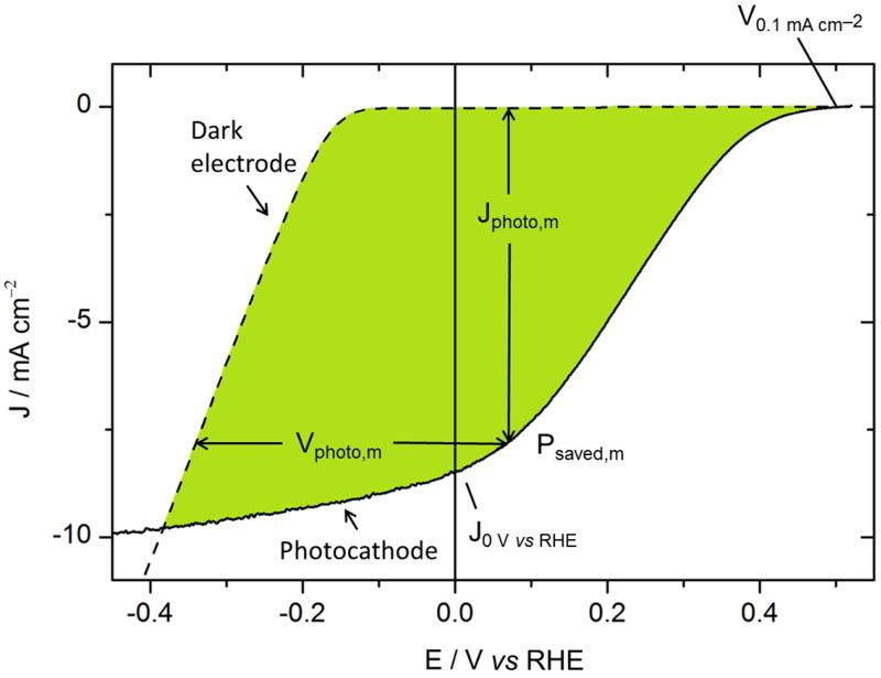
Φsaved,ideal depends on the efficiency of both the photoproduction of charges in P3HT:PCBM and their utilization by the catalyst, which are not differentiated in this figure-of-merit. It may thus be interesting to consider another quantity, which is less catalyst-dependent: the power-saved metric relative to a non-photoactive dark electrode with an identical catalyst and measured in an identical three-electrode electrochemical cell (Fig. 8). Φsaved,NPAC (NPAC = non-photoactive, identical catalyst) is calculated following equ. (2):1
| (2) |
where ηF is the Faradaic efficiency assumed to be 100 % again, Pin is the power of the incident illumination, and Jphoto,m and Vphoto,m are the photocurrent and photovoltage at the maximum power point.
Figure. 8.
Current-voltage characteristic of an ITO\PEDOT:PSS\P3HT:PCBM\LiF\Al\Ti\MoS3 photocathode (black line) and of an ITO\MoS3 dark cathode (black dashed line). The photovoltage at a given current is thus evaluated from the potential under illumination compared to that of the same catalyst directly deposited on ITO.
For the comparison of a photoelectrode, Φsaved,ideal and Φsaved,NPAC are both important values because Φsaved,ideal reflects the optimum power point for the use of the photoelectrode in practical applications (i.e. depending on the performance of both the photovoltaic material and the catalyst) while Φsaved,NPAC reflects the photovoltage and photocurrent of a photocathode independently from the overpotential requirement of the catalyst.
Some details of the procedure to calculate Φsaved,NPAC are presented in SI. Fig. S7 shows the curves used in the case of the MoS3 catalyst and the LiF\Al\Ti interfacial layer. The photocurrent Jphoto is the difference between the current under illumination (Jlight, i.e. measured for the ITO\PEDOT:PSS\P3HT:PCBM\LiF\Al\Ti\MoS3 photocathode) and of the catalyst (Jdark, measured for ITO\MoS3). As expected, Jphoto increases at the same rate as Jlight when the voltage is swept in the cathodic direction. Once the onset of the HER of the catalyst is reached, Jphoto decreases with the increase of Jdark. From these data, the photovoltage Vphoto is obtained by subtracting Udark from Ulight at matching current densities. Jphoto as a function of Vphoto is shown in Fig. S8 (right Y-axis).
Table 2 presents Φsaved,ideal and Φsaved,ideal as well as the photovoltages and photocurrents in each case.
Table 2.
For different photocathodes measured at 100 mW cm−2 : Φsaved,ideal and Φsaved,NPAC at maximum power point with their corresponding current density and potential (Jmp and Vmp, Jphoto,mp and Vphoto,mp). Table S1 gathers all data of Tables 1 and 2, as well as the calculation for the ITO\PEDOT:PSS\P3HT:PCBM\LiF\Al\Ti\MoS3 at different incident power. As for Table 1, two different areas were taken into account: the current density Jphoto,mp was multiplied by the electrode area in contact with the electrolyte, while Pin was referred to the lightened area (0.5 cm2).
| Φ saved,ideal | Φ saved,NPAC | |
|---|---|---|
|
| ||
| ITO\PEDOT:PSS\P3HT:PCBM\LiF\Al\Ti\MoS3 | 0.64 % (Jm = 5.1 mA cm−2, Vm = 0.20 V) | 2.05 % (Jphoto,m = 7.8 mA cm−2, Vphoto,m = 0.41 V) |
| ITO\PEDOT:PSS\P3HT:PCBM\LiF\Al\Ti\Pt/C | 1.42 % (Jm = 6.0 mA cm−2, Vm = 0.31 V) | 1.64 % (Jphoto,m = 6.7 mA cm−2, Vphoto,m = 0.39 V) |
| ITO\PEDOT:PSS\P3HT:PCBM\Ti\MoS3 | 0.24 % (Jm = 3.9 mA cm−2, Vm = 0.11 V) | 1.30 % (Jphoto,m = 7.7 mA cm−2, Vphoto,m = 0.30 V) |
| ITO\PEDOT:PSS\P3HT:PCBM\C60\MoS3 | 0.006 % (Jm = 0.4 mA cm−2, Vm = 0.008 V) | 0.14 % (Jphoto,m = 2.1 mA cm−2, Vphoto,m = 0.30 V) |
First, the Φsaved,NPAC and Φsaved,ideal for the same system with LiF\Al\Ti as interlayer and MoS3 as catalyst are significantly different: Φsaved,NPAC (2.05 %) is 3.2 times larger than Φsaved,ideal (0.64 %). This higher Φsaved,NPAC is due to both a higher photovoltage and a higher photocurrent at which the maximum power point is obtained: Vphoto,m is 0.41 V while Vm is only 0.2 V. This 0.21 V loss is a consequence of the overpotential requirement of the catalyst, and in the photocathode, a significant part of the photovoltage is thus used to overcome the overpotential requirement of MoS3 to mediate HER. Moreover, the photocurrent Jphoto,m (7.8 mA cm−2) is 50 % larger than Jm (5.1 mA cm−2) because the saturation photocurrent is barely reached at positive potentials (towards the RHE). On the contrary, with the Pt/C catalyst (ITO\PEDOT:PSS\P3HT:PCBM\LiF\Al\Ti\Pt/C photocathode), which mediates HER at much lower overpotential values than MoS3, the difference between the two figures-of-merit is much less: Φsaved,NPAC (1.64 %) is only 1.2 times Φsaved,ideal (1.42 %), because the photovoltage does not need to be used for overcoming the overpotential of the catalyst (Vm and Vphoto,m are 0.31 V and 0.39 V respectively).
In a next step, Φsaved,NPAC and Φsaved,ideal can be compared for two photocathodes with different catalysts (Pt/C and MoS3) but with identical interfacial layers (LiF\Al\Ti). In this case, Φsaved,NPAC with MoS3 and with Pt (2.05 % and 1.64 %) are closer than the Φsaved,ideal (0.64 % and 1.42 %) because the maximum photovoltages in both photocathodes are similar (0.41 V and 0.39 V), as well as the maximum photocurrent densities (7.8 and 6.7 mA cm−2). Thus, Φsaved,NPAC is independent from the catalyst performance, and is a suitable figure-of-merit for the comparison of different light-harvesting modules. It is illustrated by the ITO\PEDOT:PSS\P3HT:PCBM\Ti\MoS3 photocathode, whose Φsaved,NPAC is 1.3 %, i.e. 1.6 times less than with the LiF\Al\Ti interfacial layer (2.05 %) with identical catalysts (MoS3). It shows that the lower efficiency obtained with Ti is due to the light-harvesting part and not to the catalyst overpotential requirement. This effect is even more pronounced with the C60 interlayer.
4. Conclusion
Photocathodes based on P3HT:PCBM solar cells and a noble metal-free catalyst, MoS3, evolve hydrogen at RHE potential thanks to the introduction of interfacial layers, which improved the charge transfer from the photocathode to the catalyst mediating proton reduction. Moreover, these interfacial layers bury the P3HT:PCBM p/n junction, removing the constraint of energy level alignment between the redox potential of interest (H+/H2) and the conduction band edge position of the acceptor material (here PCBM).
The organic cell provides a photovoltage of 0.6 V which is close to the open circuit potential measured in solid state devices when the metallic LiF\Al\Ti layer is used, while the photocurrent at RHE potential reaches 8 mA cm−2, corresponding to a value of ratiometric saved power of 2.05 %. Increased stability is obtained by using only Ti as interfacial layer, though it results in a ratiometric saved power value of 1.30 % due to a 150 mV cathodic shift of the J-V curve. The photovoltage and photocurrent are lower in the case of C60, probably because of resistive losses appearing at the interfaces. As described in a recent work,37 TiOx layers also works as efficient interfacial layer in this context in combination with Pt as HER catalyst. Using other types of organic and polymeric photovoltaic materials delivering a higher VOC, e.g. PCDTBT (poly[N- 9′-heptadecanyl-2,7-carbazole-alt-5,5-(4,7-di-2-thienyl-2′,1′,3′-benzothiadiazole]),38 the photovoltage values could be further increased. These promising results show that a rational improvement of the performances of such organic solar cell-based photoelectrodes is possible through the combination of interfacial layers, catalysts and organic semiconductor materials. The stability of the interfacial layers and consequently of the devices must be further improved for their integration into practical application, so that further steps will include the search for novel formulation allowing a more durable protection of the photo-active components against corrosion and integration of multi-junction organic solar cells.
Supplementary Material
Acknowledgements
We are indebted to the CEA for the financial support, through the DSM Energy Program for the Ph.D. thesis grant assigned to RB. This work was partially supported by the French National Research Agency (Labex program, ARCANE, ANR-11-LABX-0003-01 and the European Research Council under the European Union’s Seventh Framework Programme (FP/2007-2013)/ERC Grant Agreement n.306398.
Footnotes
Associated content:
Supporting information available: Details of experimental procedures, supplementary Figures (Fig. S1 – S6) and STH efficiency and ratiometric power-saved figures-of-merit (Fig. S7 and S8). This material is available free of charge via the Internet at http://pubs.acs.org.
Notes and references
- (1).Coridan RH, Nielander AC, Francis SA, McDowell MT, Dix V, Chatman SM, Lewis NS. Methods for Comparing the Performance of Energy-Conversion Systems for Use in Solar Fuels and Solar Electricity Generation. Energy Environ. Sci. 2015 DOI:10.1039/C5EE00777A. [Google Scholar]
- (2).Walter MG, Warren EL, McKone JR, Boettcher SW, Mi Q, Santori EA, Lewis NS. Solar Water Splitting Cells. Chem. Rev. 2010;110(11):6446–6473. doi: 10.1021/cr1002326. [DOI] [PubMed] [Google Scholar]
- (3).Li Z, Luo W, Zhang M, Feng J, Zou Z. Photoelectrochemical Cells for Solar Hydrogen Production: Current State of Promising Photoelectrodes, Methods to Improve Their Properties, and Outlook. Energy Environ. Sci. 2013;6(2):347–370. [Google Scholar]
- (4).Protti S, Albini A, Serpone N. Photocatalytic Generation of Solar Fuels from the Reduction of H2O and CO2: A Look at the Patent Literature. Phys. Chem. Chem. Phys. 2014;16(37):19790–19827. doi: 10.1039/c4cp02828g. [DOI] [PubMed] [Google Scholar]
- (5).Jacobsson TJ, Fjällström V, Edoff M, Edvinsson T. Sustainable Solar Hydrogen Production: From Photoelectrochemical Cells to PV-Electrolyzers and Back Again. Energy Environ. Sci. 2014;7:2056–2070. [Google Scholar]
- (6).Lanzarini E, Antognazza MR, Biso M, Ansaldo A, Laudato L, Bruno P, Metrangolo P, Resnati G, Ricci D, Lanzani G. Polymer-Based Photocatalytic Hydrogen Generation. J. Phys. Chem. C. 2012;116(20):10944–10949. [Google Scholar]
- (7).Krebs FC, Hösel M, Corazza M, Roth B, Madsen MV, Gevorgyan SA, Søndergaard RR, Karg D, Jørgensen M. Freely Available OPV - The Fast Way to Progress. Energy Technol. 2013;1(7):378–381. [Google Scholar]
- (8).Licht S, Wang B, Mukerji S, Soga T, Umeno M, Tributsch H. Over 18 % Solar Energy Conversion to Generation of Hydrogen Fuel ; Theory and Experiment for Efficient Solar Water Splitting. Int. J. Hydrogen Energy. 2001;26:653–659. [Google Scholar]
- (9).Rocheleau RE, Miller EL, Misra A. High-Efficiency Photoelectrochemical Hydrogen Production Using Multijunction Amorphous Silicon Photoelectrodes. Energy Fuels. 1998;12(1):3–10. [Google Scholar]
- (10).Yamada Y, Matsuki N, Ohmori T, Mametsuka H, Kondo M, Matsuda A, Suzuki E. One Chip Photovoltaic Water Electrolysis Device. Int. J. Hydrogen Energy. 2003;28(11):1167–1169. [Google Scholar]
- (11).Reece SY, Hamel JA, Sung K, Jarvi TD, Esswein AJ, Pijpers JJH, Nocera DG. Wireless Solar Water Splitting Using Silicon-Based Semiconductors and Earth-Abundant Catalysts. Science. 2011;334:645–649. doi: 10.1126/science.1209816. [DOI] [PubMed] [Google Scholar]
- (12).Morales-Guio CG, Tilley SD, Vrubel H, Grätzel M, Hu X. Hydrogen Evolution from a CoppeRI) Oxide Photocathode Coated with an Amorphous Molybdenum Sulphide Catalyst. Nat. Commun. 2014;5:3059. doi: 10.1038/ncomms4059. [DOI] [PubMed] [Google Scholar]
- (13).Lin C-Y, Lai Y-H, Mersch D, Reisner E. Cu2O|NiOx Nanocomposite as an Inexpensive Photocathode in Photoelectrochemical Water Splitting. Chem. Sci. 2012;3(12):3482–3487. [Google Scholar]
- (14).Park Y, McDonald KJ, Choi K-S. Progress in Bismuth Vanadate Photoanodes for Use in Solar Water Oxidation. Chem. Soc. Rev. 2013;42:2321–2337. doi: 10.1039/c2cs35260e. [DOI] [PubMed] [Google Scholar]
- (15).Abdi FF, Han L, Smets AHM, Zeman M, Dam B, van de Krol R. Efficient Solar Water Splitting by Enhanced Charge Separation in a Bismuth Vanadate-Silicon Tandem Photoelectrode. Nat. Commun. 2013;4:2195. doi: 10.1038/ncomms3195. [DOI] [PubMed] [Google Scholar]
- (16).Green MA, Emery K, Hishikawa Y, Warta W, Dunlop ED. Solar Cell Efficiency Tables (version 45) Prog. Photovolt: Res. Appl. 2015;23:1–9. [Google Scholar]
- (17).Li W, Furlan A, Hendriks KH, Wienk MM, Janssen RAJ. Efficient Tandem and Triple-Junction Polymer Solar Cells. J. Am. Chem. Soc. 2013;135(15):5529–5532. doi: 10.1021/ja401434x. [DOI] [PubMed] [Google Scholar]
- (18).Chen SN, Heeger AJ, Kiss Z, MacDiarmid AG, Gau SC, Peebles DL. Polyacetylene, (CH)x: Photoelectrochemical Solar Cell. Appl. Phys. Lett. 1980;36(1):96–98. [Google Scholar]
- (19).Yanagida S, Kabumoto A, Mizumoto K, Pac C, Yoshino K. Poly(p-Phenylene)-Catalysed Photoreduction of Water to Hydrogen. J. Chem. Soc. Chem. Commun. 1985:474–475. [Google Scholar]
- (20).El-Rashiedy OA, Holdcroft S. Photoelectrochemical Properties of Poly (3-Alkylthiophene) Films in Aqueous Solution. J. Phys. Chem. 1996;100:5481–5484. [Google Scholar]
- (21).Abe T, Nagai K. Novel Photofunctions of Bilayer Composed of P-Type Phthalocyanine and N-Type Organic Semiconductor as Photoelectrodes in the Water Phase. Org. Electron. 2007;8(2-3):262–271. [Google Scholar]
- (22).Suppes G, Ballard E, Holdcroft S. Aqueous Photocathode Activity of Regioregular poly(3-Hexylthiophene) Polym. Chem. 2013;4(20):5345–5250. [Google Scholar]
- (23).Abe T, Tobinai S, Taira N, Chiba J, Itoh T, Nagai K. Molecular Hydrogen Evolution by Organic p/n Bilayer Film of Phthalocyanine/Fullerene in the Entire Visible-Light Energy Region. J. Phys. Chem. C. 2011;115(15):7701–7705. [Google Scholar]
- (24).Lattach Y, Fortage J, Deronzier A, Moutet J-C. Polypyrrole-Ru(2,2′-bipyridine)32+/MoSx Structured Composite Film As a Photocathode for the Hydrogen Evolution Reaction. ACS Appl. Mater. Interfaces. 2015;7(8):4476–4480. doi: 10.1021/acsami.5b00401. [DOI] [PubMed] [Google Scholar]
- (25).Bourgeteau T, Tondelier D, Geffroy B, Brisse R, Laberty-Robert C, Campidelli S, de Bettignies R, Artero V, Palacin S, Jousselme B. A H2-Evolving Photocathode Based on Direct Sensitization of MoS3 with an Organic Photovoltaic Cell. Energy Environ. Sci. 2013;6(9):2706–2713. doi: 10.1039/C3EE41321G. [DOI] [PMC free article] [PubMed] [Google Scholar]
- (26).Morales-Guio CG, Hu X. Amorphous Molybdenum Sulfides as Hydrogen Evolution Catalysts. Acc. Chem. Res. 2014;47(8):2671–2681. doi: 10.1021/ar5002022. [DOI] [PubMed] [Google Scholar]
- (27).Guerrero A, Haro M, Bellani S, Antognazza MR, Meda L, Gimenez S, Bisquert J. Organic Photoelectrochemical Cells with Quantitative Photocarrier Conversion. Energy Environ. Sci. 2014;7(11):3666–3673. [Google Scholar]
- (28).Vrubel H, Merki D, Hu X. Hydrogen Evolution Catalyzed by MoS3 and MoS2 Particles. Energy Environ. Sci. 2012;5(3):6136–6144. [Google Scholar]
- (29).Seger B, Laursen AB, Vesborg PCK, Pedersen T, Hansen O, Dahl S, Chorkendorff I. Hydrogen Production Using a Molybdenum Sulfide Catalyst on a Titanium-Protected n+p-Silicon Photocathode. Angew. Chem. Int. Ed. 2012;51(36):9128–9131. doi: 10.1002/anie.201203585. [DOI] [PubMed] [Google Scholar]
- (30).Seger B, Pedersen T, Laursen AB, Vesborg PCK, Hansen O, Chorkendorff I. Using TiO2 as a Conductive Protective Layer for Photocathodic H2 Evolution. J. Am. Chem. Soc. 2013;135(3):1057–1064. doi: 10.1021/ja309523t. [DOI] [PubMed] [Google Scholar]
- (31).Seger B, Tilley SD, Pedersen T, Vesborg PCK, Hansen O, Grätzel M, Chorkendorff I. Silicon Protected with Atomic Layer Deposited TiO2: Conducting versus Tunnelling through TiO2. J. Mater. Chem. A. 2013;1(47):15089–15094. [Google Scholar]
- (32).Seger B, Tilley DS, Pedersen T, Vesborg PCK, Hansen O, Grätzel M, Chorkendorff I. Silicon Protected with Atomic Layer Deposited TiO2: Durability Studies of Photocathodic H2 Evolution. RSC Adv. 2013;3(48):25902–25907. [Google Scholar]
- (33).Jacobsson TJ, Fjällström V, Sahlberg M, Edoff M, Edvinsson T. A Monolithic Device for Solar Water Splitting Based on Series Interconnected Thin Film Absorbers Reaching over 10% Solar-to-Hydrogen Efficiency. Energy Environ. Sci. 2013;6(12):3676–3683. [Google Scholar]
- (34).Nielander AC, Shaner MR, Papadantonakis KM, Francis SA, Lewis NS. A Taxonomy for Solar Fuels Generators. Energy Environ. Sci. 2015;8(1):16–25. [Google Scholar]
- (35).Rikitake K, Akiyama T, Takashima W, Kaneto K. Relationships between Crystallinity and Conductivity in Evaporated C60 Films. Synth. Met. 1997;86:2357–2358. [Google Scholar]
- (36).Labille J, Brant J, Villiéras F, Pelletier M, Thill A, Masion A, Wiesner M, Rose J, Bottero J-Y. Affinity of C60 Fullerenes with Water. Fullerenes, Nanotubes, Carbon Nanostruct. 2006;14(2-3):307–314. [Google Scholar]
- (37).Haro M, Solis C, Molina G, Otero L, Bisquert J, Gimenez S, Guerrero A. Towards Stable Solar Hydrogen Generation Using Organic Photoelectrochemical Cells. J. Phys. Chem. C. 2015;119(12):6488–6494. [Google Scholar]
- (38).Park SH, Roy A, Beaupré S, Cho S, Coates N, Moon JS, Moses D, Leclerc M, Lee K, Heeger AJ. Bulk Heterojunction Solar Cells with Internal Quantum Efficiency Approaching 100% Nat. Photonics. 2009;3(5):297–302. [Google Scholar]
Associated Data
This section collects any data citations, data availability statements, or supplementary materials included in this article.


