Abstract
Purpose
To create and characterize a physical Windkessel module that can provide realistic and predictable vascular impedances for in-vitro flow experiments used for computational fluid dynamics validation, and other investigations of the cardiovascular system and medical devices.
Methods
We developed practical design and manufacturing methods for constructing flow resistance and capacitance units. Using these units we assembled a Windkessel impedance module and defined its corresponding analytical model incorporating an inductance to account for fluid momentum. We tested various resistance units and Windkessel modules using a flow system, and compared experimental measurements to analytical predictions of pressure, flow, and impedance.
Results
The resistance modules exhibited stable resistance values over wide ranges of flow rates. The resistance value variations of any particular resistor are typically within 5% across the range of flow that it is expected to accommodate under physiologic flow conditions. In the Windkessel impedance modules, the measured flow and pressure waveforms agreed very favorably with the analytical calculations for four different flow conditions used to test each module. The shapes and magnitudes of the impedance modulus and phase agree well between experiment and theoretical values, and also with those measured in-vivo in previous studies.
Conclusions
The Windkessel impedance module we developed can be used as a practical tool to provide realistic vascular impedance for in-vitro cardiovascular studies. Upon proper characterization of the impedance module, its analytical model can accurately predict its measured behavior under different flow conditions.
Keywords: Windkessel, vascular impedance, in-vitro validation, blood flow, Flow resistance, Flow capacitance, Flow impedance, Flow inductance, Boundary condition
1. Introduction
Computational fluid dynamics (CFD) is a powerful tool for quantifying hemodynamic forces in the cardiovascular system. In CFD simulations, realistic outflow boundary conditions are necessary to represent physical properties of the downstream vasculature not modeled in the numerical domain, and to produce physiologic levels of pressure [1]. While various types of boundary condition implementations exist [2-6], previous studies showed that impedance-based boundary condition is the preferred approach for coupling wave reflections from the downstream vasculature into the numerical domain [1], and that simple lumped-parameter model representations can provide realistic impedances similar to those provided by a more complicated method employing a distributed parameter model [2]. The Windkessel model, due to its simplicity and ability to provide physiologically realistic impedances [7-10], is a practical method of prescribing suitable boundary conditions to the numerical domain in CFD simulations.
The Windkessel model is represented as a circuit containing lumped elements of resistance, capacitance, and inductance. Although these elements are more generally interpreted in an electrical system, there is a direct analogy between the governing equations of an electric circuit and those of a fluid system, where the fluid pressure directly parallels voltage, the fluid volume parallels electrical charge, and the volumetric flow rate parallels electrical current. For example, the relationship between voltage and current related by electrical resistance as described by the equation V=IR, can be directly modified into P=QR to describe the relationship between pressure and flow rate related by the fluid resistance.
When used to mimic vascular impedances, associations exist between the lumped component values in a Windkessel model and in-vivo physiological parameters. The resistance and inductance values are associated with the geometry and architecture of the downstream vasculature, which are functions of both the anatomy and the vascular tone. The capacitance value is most affected by the physical properties and the vascular tone of the large arteries. Since the blood vessel anatomy and physical properties, as well as the vascular tone, do not vary significantly within the time frames of a cardiac cycle, computationally, it is the general practice to implement the Windkessel model with fixed component values.
In order to validate CFD against experimental data, we must develop methods to reliably construct a physical model of the Windkessel boundary condition such that there is a direct parallel between the experimental setup and the CFD simulation. In this paper we present the theories, principles, practical design considerations, and manufacturing processes for physically constructing the resistance and capacitance components of a Windkessel impedance module, such that the component values are predictable and constant throughout their operating ranges. We also define an analytical model to describe the physical Windkessel module, incorporating an inductance to account for fluid momentum. We manufactured several resistance units and tested them independently in a flow loop to verify their operations. We then assembled two Windkessel modules that mimic the thoracic-aortic, and renal, impedances, tested them under physiologic pulsatile flow conditions, and compared experimental measurements to analytical predictions of pressure and flow.
2. Methods
2.1 Determining Target Windkessel Component Values
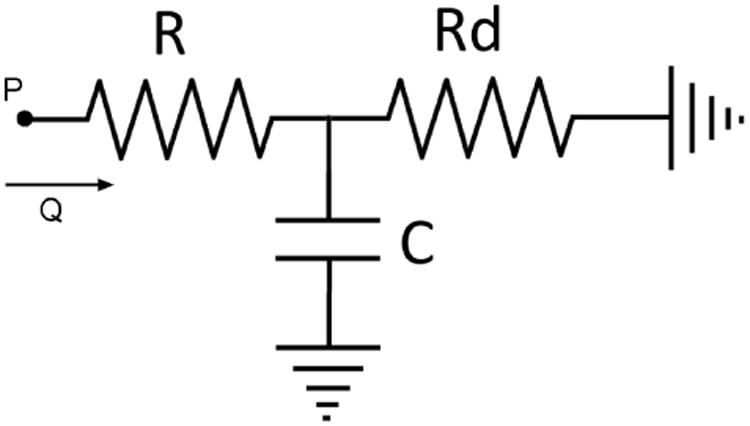
We must first determine the target values to aim for in the design and construction of the Windkessel components. We perform the component value estimation with a basic three element Windkessel model consisting of a proximal resistor (Rp), a capacitor (C), and a distal resistor (Rd) as shown in Fig 1. The target component values are those that would result in the desired pressure and flow relationship reflecting the particular vascular impedance we wish to mimic. For a periodic flow condition, the pressure and flow is related by the equation in the frequency domain:
Fig 1. A basic three-element Windkessel model for component value estimation purpose.
| (1) |
Where ω is the frequency, Q is the volumetric flow rate, and Z is the impedance of the three-element Windkessel circuit:
| (2) |
In previous reports, blood flow waveforms at various locations in the vascular tree have been obtained with imaging modalities such as ultrasound or phase-contrast magnetic resonance imaging [11-13], and pressure waveforms have been obtained with pressure cuffs or arterial catheters [14]. Using the available in-vivo flow and pressure waveform data, together with equations 1 and 2, we can perform an iterative process to find the target values for the Windkessel components, in order for the Windkessel model to mimic the in-vivo vascular impedance at a specific location. We begin by using the flow data and initial guesses of the component values as input parameter into equations 1 and 2 to calculate a resulting pressure waveform. We then adjust the component values with the goal of matching the calculated pressure to the in-vivo measured pressure waveform. For any given input flow, we can adjust the total resistance (sum of Rp and Rd) to vertically shift the calculated pressure waveform, and adjust the ratio of Rp/Rd as well as the capacitance to modulate the shape and pulse amplitude of the calculated pressure waveform. Once we determine the component values which give the desired pressure and flow relationship, we then consider them the target values in the design and construction of the components.
2.2 Flow Resistance Module
Theory and Construction Principles
In Poiseuille's solution for laminar flow in a straight cylinder, the relationship between the pressure drop across the cylinder (ΔP) and volumetric flow rate (Q) is:
| (3) |
The flow resistance defined as R=ΔP/Q is then:
| (4) |
where μ is the dynamic viscosity of the fluid, l is the length of the cylinder, and r is the radius of the cylinder.
Equation 3 holds true in a laminar flow condition, where the resistance is constant and independent of flow rate. In turbulent flow, however, the additional energy loss leads to the pressure drop across the flow channel becoming proportional to the flow rate squared (ΔP α Q2), implying that the total effective resistance as defined by R=ΔP/Q is proportional to the flow rate (R α Q). Since our goal is to create a constant resistance that is independent of flow rate, it is thus important to avoid turbulence and maintain laminar flow. An approximate condition for laminar flow in a circular cylinder is the satisfaction of the following equation for Reynolds number:
| (5) |
where ν is flow velocity, r is the radius of the flow conduit, and υ is the kinematic viscosity of the fluid.
Equation 4 shows that with a single cylindrical channel of a given length, a high flow resistance can be achieved by drastically decreasing the cylinder radius. According to equation 5, however, decreasing the radius means that the flow conduit can only accommodate a lower flow rate while maintaining laminar flow. For physiological ranges of flows and impedances, it is generally the case that an Rp made from a single flow channel of a reasonable length would not be able to accommodate the required amount of flow. For example, the typical infra-renal aortic impedance results in an Rp of approximately 500 Ba*s/cm3, and the peak flow at that anatomical location is approximately 100 cc/s. Using a single cylindrical channel of length 10cm, and a fluid kinematic viscosity of 0.04 g/cm*s, the radius of such a resistor would be 0.22cm. Equation 5 indicates that the maximum flow rate this resistor can accommodate in laminar flow condition is 33 cc/s, much less than the peak flow that will flow through it.
We present mathematically how such a problem can be overcome by using a large number of small channels in parallel, which simultaneously allows for high resistance and laminar flow at high flow rates. Consider “N” number of parallel flow channels with radius “r”. We define:
A – combined cross sectional area of all channels
Q – combined volumetric flow through all channels
Qchan – volumetric flow rate through each channel
Re – Reynolds number
Rchan – resistance of each channel
Rtotal – combined resistance of all the parallel channels
The following two equations describe the geometry and resistances of the flow channels:
| (6) |
| (7) |
From equations 4, 5 and 6, we obtain the following proportionalities:
| (8) |
| (9) |
| (10) |
Substituting equations 8 and 6 into 7
| (11) |
Substituting equation 9 into 11
| (12) |
Substituting equation 10 into 12 and re-arranging, we finally have
| (13) |
Equation 13 indicates that in order to achieve a high resistance at a high flow rate, while maintaining a low Reynolds number, a large number of parallel channels is required. Fig 2a is an illustration that shows the relationship between N and the maximum laminar flow rate for various values of Rtotal.
Fig 2.
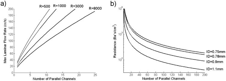
a) Maximum Laminar Flow Rate v.s. Number of Parallel Channels for Various Resistance Values
b) Resistance v.s. Number of Parallel Channels for Various Standard Capillary Tube Inside Diameters (ID)
Calculated using:
Fluid dynamic viscosity = 0.046 g/cm*s
Capillary Tube Length = 10 cm
Practical Design and Construction Methods
To assemble a large number of small parallel channels in a practical and robust way, we placed thin-walled glass capillary tubes (Sutter Instrument, CA) inside a plexiglass cylinder as shown in Fig 3a. We applied a small amount of silicone rubber adhesive sealant (RTV 102, GE Silicones, NY) in between the capillary tubes around their middle section to adhere the tubes to one another, and to block fluid passageways through the gaps in between the tubes. We then applied a small amount of epoxy (5 Minute Epoxy, Devcon, MA) between the plexiglass surface and the bundle of capillary tubes to secure the capillary tubes inside the plexiglass cylinder.
Fig 3. a) Capillary Tube Resistance Module Construction b) Switchable Resistance Setup.

The theoretical resistance of the resistance module is given by:
| (14) |
where μ is the dynamic viscosity of the working fluid, l is the length of the capillary tubes, r is the inside radius of each individual capillary tube, and N is the total number of capillary tubes in parallel [15].
For a standard capillary tube length of 10cm, Fig 2b shows the relationship between the number of tubes and the resulting resistance for various standard capillary tube sizes that can be readily purchased.
Using the same principle of parallel channels, Fig 3b shows a method for creating a switchable resistance module where the resistance value can be changed during an experiment. We placed multiple resistance modules in parallel, with control valves that open and close to add in or remove parallel resistor(s) in order to decrease or increase the effective total resistance.
The resistance module must be connected to tubing at each end. It is important to ensure that laminar flow is maintained throughout the connection tubing, and that diameter changes at the connection junctions are minimized to avoid the creation of turbulence. We constructed Table 1 to aid the design process of choosing an appropriate combination of a standard capillary tube size and connection tubing size, such that the resistance module can connect smoothly to its inlet and outlet tubing, and that the connection tubing itself can also accommodate the maximum flow rate required. The maximum laminar flow for any particular flow conduit diameter can be calculated from equation 5, and is listed below each conduit diameter in the table. Note that the Reynolds number within the capillary tubes is much lower than that in the connection tubing (due to the smaller diameter of the capillary tubes), thus the critical factor in maintaining laminar flow is the connection tubing diameter. From Table 1, we look up a resistance value that is close to the desired target value, and where the conduit diameter can accommodate the maximum flow expected through the resistance unit to be built. This gives the optimal capillary tube size for constructing the resistance module. Once we determine the capillary tube size, we then use a circle packing algorithm[16] to determine the precise plexiglass cylinder diameter required to house the specific number of capillary tubes needed for obtaining the desired resistance. Upon completing the actual construction of the resistance module, we manually count the number of capillary tubes in the plexiglass cylinder, and use the resulting count, together with the measured dynamic viscosity of the working fluid and equation 14, to determine the theoretical resistance of the module.
Table 1. Estimated Resistance Values Resulting From Various Combinations of Conduit Diameter (Maximum Laminar Flow Rate), and Capillary Tube Size.
| Capillary Tubes *OD/ID (mm) | Estimated Resistance (Ba*s/cm3) for Conduit Diameters: (And Maximum Laminar Flow Rates): | |||||
|---|---|---|---|---|---|---|
| 1″ (200cc/s) | 3/4″ (150 cc/s) | 5/8″ (125 cc/s) | 1/2″ (100 cc/s) | 3/8″ (75 cc/s) | 1/4″ (50 cc/s) | |
| 2/1.56 | 231 | 410 | 591 | 923 | 1641 | 3693 |
| 1.5/1.1 | 525 | 934 | 1345 | 2101 | 3735 | 8404 |
| 1.2/0.9 | 750 | 1334 | 1920 | 3000 | 5334 | 12002 |
| 1/0.78 | 923 | 1641 | 2364 | 3693 | 6566 | 14773 |
| 1/0.75 | 1080 | 1920 | 2765 | 4321 | 7681 | 17282 |
Calculated using:
Fluid dynamic viscosity = 0.046 g/cm*s
Fluid density = 1.1 g/mL
Capillary Tube Length = 10 cm
Circle packing density = 0.85 by area
OD/ID stands for Outside Diameter/Inside Diameter
2.3 Flow Capacitance Module
The capacitance of a fluid system is define as C=ΔV/ΔP where ΔV and ΔP are the changes in volume and pressure. In a closed system at constant temperature, an ideal gas exhibits the behavior PV=(P+ΔP)(V-ΔV), where P and V are the reference pressure and volume. The capacitance of a pocket of air is then:
| (15) |
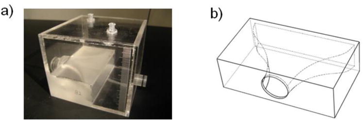
We constructed the capacitance module with a plexiglass box that can trap a precise amount of air, which acts as a capacitance in the system (Fig 4a). Equation 15 indicates that, as fluid enters the capacitor and compresses the air, the capacitance of the module would decrease. For small changes in volume relative to the reference volume, however, a reasonably constant capacitance can be maintained. As fluid enters and exits the box, the vertical level of the fluid in the box rises and falls slightly. The varying fluid level contributes to an additional capacitance that is in series with the capacitance due to air compression. The pressure change in the fluid due to the varying fluid level under the effects of gravity and fluid mass is:
Fig 4. a) Capacitance Module Construction b) Capacitor Inlet Contour.
| (16) |
where ρ is the fluid density, g is the gravitational constant, and A is the area of the fluid/air interface (assuming a column of fluid with constant cross-sectional area). The capacitance due to the varying fluid level is then:
| (17) |
Since Cv is in series with Ca the overall capacitance can be approximated by Ca alone if Cv≫Ca:
| (18) |
In the actual construction of the capacitance module, we designed the box to be large enough so that the approximation in equation 18 is true. We also designed a smooth contour for the inlet of the capacitance module (Fig 4b) in order to minimize flow turbulences and thus avoid parasitic resistances. In addition, we included two access ports at the top of the capacitance module for air volume modulation and pressure measurements, and a graduated scale on the sidewalls to obtain air volume information (Fig 4a).
2.4 Flow Inductance
The flow inductance is an inherent parameter of a fluid system resulting from the fluid mass. It describes how a force, manifest as a pressure differential, is required to accelerate a body of fluid. The inductance in a fluid system creates a pressure drop in response to a change in flow as described by the equation:
| (19) |
where L is the inductance value.
Consider a volume of fluid with density “ρ” and mass “m” inside a cylinder with cross-sectional area “A” and length “l”. The acceleration of the fluid can be expressed as:
| (20) |
The force “F” required to accelerate the fluid mass, and applied to the cross-sectional area results in a pressure differential:
| (21) |
Substituting Newton's second law and equation 20 into equation 21:
| (22) |
Equations 19 and 22 together indicate that L = m/A2. Since “m” is related to the density and volume of the fluid, we can express the inductance as:
| (23) |
Equation 23 allows direct calculation of the inductance value of a fluid body from the fluid density and the geometry of the flow conduit.
2.5 Assembled Windkessel Module & Corresponding Analytical Model
We assembled the Windkessel impedance module by putting together two resistors and one capacitor as shown in Fig 5a. In the analytical model, we must take into account the inductive effects of the fluid body [8]. We thus model the impedance module as an LRCR circuit as shown in Fig 5b. Note that even though there is an inductance associated with the downstream resistance Rd, since the flow through Rd is typically nearly constant, the presence of the inductance is transparent to the operation of the impedance unit. Incorporating only the upstream inductance in the analytical model is sufficient to fully capture the behavior of the physical impedance module.
Fig 5. a) Assembled Impedance Module. b) Final Analytical Model of Impedance Module.

3. Experimental Testing & Data Analysis
3.1 Resistance Module
We tested the operation of the resistance modules with a setup depicted in Fig 6. We used a 1/12 horse-power, 3100RPM, steady flow pump (Model 3-MD-HC, Little Giant Pump Co., OK) to drive flow through the resistance module. The working fluid in the flow system was a 40% glycerol solution which has a dynamic viscosity similar to that of blood. For data acquisition, we used an ultrasonic transit-time flow probe to monitor the flow through the system. We placed the externally clamped flow probe (8PXL, Transonic Systems, NY) around a short section of Tygon tubing R3603, and sent the signals from the probe into a flowmeter (TS410, Transonic Systems, NY). For pressure measurements, we inserted catheter pressure transducers (“Mikro-Tip” SPC-350, Millar Instruments, Huston, TX) into the flow conduit immediately upstream and downstream of the resistance module to capture instantaneous pressure readings, and obtain the pressure drop across the resistor. We sent the signals from each catheter pressure transducer into a pressure control unit (TCB-600, Millar Instruments, TX) which produces an electrical output of 0.5V per 100mmHg of pressure. We recorded the data from the flow meter and the pressure control units at a sample rate of 2kHz using a data acquisition unit (USB-6259, National Instruments, Austin, TX) and a LabVIEW program (LabVIEW v.8, National Instruments, Austin, TX). We averaged 8000 samples of flow and pressure (effectively, 4 seconds of flow and pressure) to obtain each data point. We then divided the measured pressure drop across the resistor by the measured volumetric flow rate through the resistor to obtain the resistance value.
Fig 6. Resistance Module Steady Flow Testing Setup.
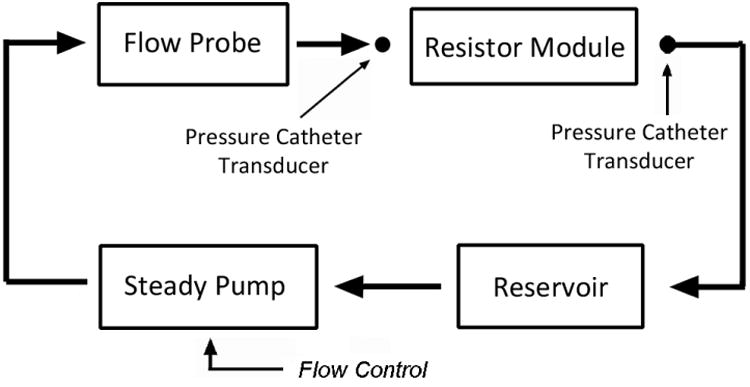
The flow control for the steady pump consisted of a LabVIEW program that directed the data acquisition unit to send a voltage to an isolation amplifier (AD210, Analog Devices, MA), which then produced the same voltage to feed into a variable frequency drive (Stratus, Control Resources Inc., MA) that drove the flow pump to produce different constant flow rates through the flow loop. The purpose of including the isolation amplifier in the signal chain was to electronically de-couple the high-power operation of the variable frequency pump drive from the data acquisition unit to avoid signal interference.
We tested several resistance modules that we built. We also tested the resistance of a partially closed ball valve, which has commonly been used as a method to produce flow resistance in previous literatures [17, 18]. We adjusted the relative resistance of the ball valve by adjusting the proportion that the valve was closed.
3.2 Assembled Windkessel Module
We tested the assembled Windkessel impedance modules using a setup depicted in Fig 7. We used a custom-built, computer-controlled pulsatile pump, in parallel with a 1/12 horse-power, 3100RPM, steady flow pump (Model 3-MD-HC, Little Giant Pump Co., OK) with a ball valve attached at its outlet for steady flow rate control, to produce physiological-level, pulsatile, and cyclic flow waveforms into the Windkessel module. The working fluid in the flow system was a 40% glycerol solution which has a dynamic viscosity similar to that of blood. For data acquisition, we used two ultrasonic transit-time flow probes to monitor the volumetric flows through Rp and Rd. We placed externally clamped flow probes (8PXL & 6PXL, Transonic Systems, NY) around short sections of Tygon tubing R3603, and sent the signals from the probes into two separate channels of a flowmeter (TS410, Transonic Systems, NY). For pressure measurements, we inserted catheter pressure transducers (“Mikro-Tip” SPC-350, Millar Instruments, Huston, TX) into the flow conduits and into the capacitor chamber to capture the pressure waveforms at three points in the circuit. We sent the signals from each catheter pressure transducer into a pressure control unit (TCB-600, Millar Instruments, TX) which produces an electrical output of 0.5V per 100mmHg of pressure. We recorded the data from the flow meter and the pressure control units at a sample rate of 96 samples per second using a data acquisition unit (USB-6259, National Instruments, Austin, TX) and a Lab VIEW program (Lab VIEW v.8, National Instruments, Austin, TX). We averaged approximately 50 cycles of flow and pressure data to obtain one representative cycle of flow and pressure waveforms. We used the pressures measured at P3 as the ground reference, and subtracted it from the pressures measured at P1 and P2, to obtain the true pressure waveforms at P1 and P2.
Fig 7. Impedance Module Pulsatile Flow Testing Setup.
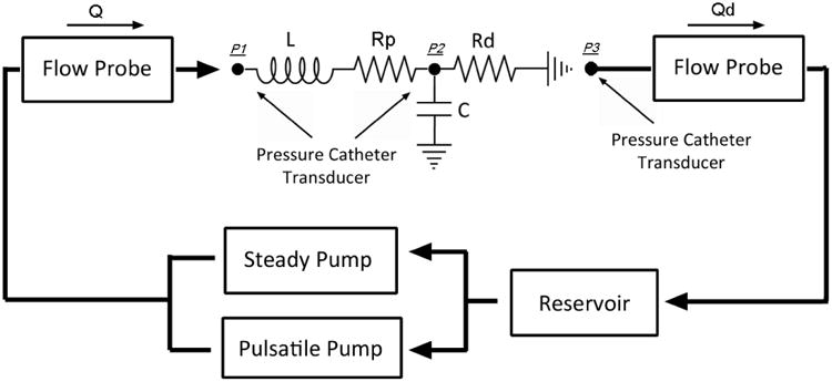
We tested two impedance modules, one mimicking the in-vivo thoracic-aortic impedance, and the other mimicking the in-vivo renal impedance, using four different input flow waveforms approximately simulating physiological flows for each module. We included input flow waveforms with different periods, as well as considerably different shapes, to investigate the impedance value behavior of each module across a wide range of flow conditions.
The impedance of the analytical Windkessel circuit in Fig 7 can be represented by the equation:
| (24) |
By prescribing the measured input flow waveform, and the values of the lumped components, we calculated the theoretical pressure waveform at P1 using equations 1 and 24. We then calculated the theoretical pressure waveform at P2 and the flow waveform Qd using the equation ΔP=QR.
4. Results & Discussions
4.1 Resistance Module
In Fig 8 we present results of resistance verses flow rate for two of the resistance modules we built, and for a partially closed ball valve. In Fig 8a, the theoretical resistance of the resistance module is 500 Ba*s/cm3. We found that the measured resistance is very close to the expected theoretical value, and that the resistance module exhibits relatively constant resistance values over the range of flow rates tested. The variation in the resistance value between flow rates of 20 cc/s and 100 cc/s is approximately 5%. The ball valve on the other hand, exhibits a resistance that varies linearly with the flow rate. Fig 8b shows results of a resistance module with theoretical resistance of 6700 Ba*s/cm3, and a ball valve adjusted to produce a higher flow resistance. We found similar results at this higher regime of resistance values. The value variation of the resistance module between flow rates of 20 cc/s and 60 cc/s is approximately 7%. Note that a resistance unit with resistance in the higher regime typically only needs to accommodate relatively low flows in its actual operation. If placed within a Windkessel module under physiologic flows, the expected maximum flow through such a resistor in Fig 8b would be approximately 30 cc/s. All of the other resistor modules we have tested (but not shown here) also exhibited similar behaviors of relatively constant resistance values over the range of flow rates they are expected to accommodate. For the resistance of the ball valve, its linear dependence on flow rate, and extrapolated value of zero at zero flow, indicate that the source of its resistance comes almost entirely from turbulence, as discussed in section 2.2. For the resistance modules we built, the slight increases in the resistance value with flow rate suggest that there is a small amount of turbulence present in the modules.
Fig 8. Resistance v.s. Flow Rate for Resistance Module with Theoretical Resistance of a) 500 Ba*s/cm3, b) 6700 Ba*s/cm3, and a Partially Closed Ball Valve.
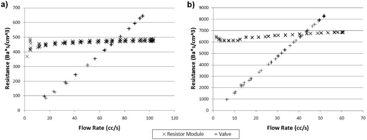
The resistance variations at the low flow regions are likely due to measurement imprecision, but not due to the actual resistance change or instability in the resistance module. Very low flows and small pressure drops across the resistor result in low signal-to-noise for both the ultrasonic flow probe and the pressure transducers, and hence difficulties in obtaining precise measurements. Fortunately, the fact that the pressure drop across the resistor is insignificant during very low flows, means that the resistance value also have minimal impact during that period. The accuracy of experimental confirmation of resistance values during the very low flow regions is thus of minimal importance.
At a fixed flow rate, we found that the resistance value of a resistance module may decrease over time by up to 5%. The decrease may be due to trapped air bubbles being purged out of the capillary tubes over time with flow (since the presence of air bubbles in the tubes would obstruct the fluid passage and result in elevated resistance). This source of resistance variation can be minimized with careful removal of air from the flow system during setup to minimize the amount of air that would be trapped in the resistor during operation.
4.2 Assembled Windkessel Module
Table 2 shows the theoretical Windkessel component values as calculated from their physical constructions, where the values of L calculated from the geometry of the physical system as described in section 2.4, the values of resistances calculated from their construction details as described in section 2.2, and the values of C calculated from the operating pressure and air volume in the capacitors as described in section 2.3. The experimental component values in Table 2, unless otherwise noted, were determined from the experimentally measured pressure and flow data, using a method similar to that described in section 2.1. For the thoracic-aortic impedance module, the inductance and resistances behaved as theoretically predicted, where the observed capacitance in the actual experiment was larger than the theoretical expectation. For the renal impedance module, we experimentally determined the resistance values from steady flow tests of the impedance module, and found that the actual resistances were about 15% less than theoretical. The inductance value, on the other hand, was higher than theoretical. The capacitance value was consistent with the theoretical prediction.
Table 2. Theoretical and Experimental Windkessel Component Values for the Thoracic-Aortic and Renal Impedance Modules.
| Thoracic-Aortic | Renal | ||||
|---|---|---|---|---|---|
| Theoretical | Experimental | Theoretical | Experimental | ||
| L | (Ba*s2/cm3) | 7 | 7 | 16 | 26 |
| Rp | (Ba*s/cm3) | 245 | 245 | 3050 | 2522 |
| C | (cm3/Ba) | 2.3 e-4 | 4.0 e-4 | 1.3 e-4 | 1.3 e-4 |
| Rd | (Ba*s/cm3) | 4046 | 4046 | 5944 | 5221 |
We prescribed the experimental component values from Table 2 in the analytical calculations of pressure and flow. Fig 9 shows pressure and flow comparisons between experimental measurements and analytical calculations for the impedance module we designed to mimic the in-vivo aortic impedance at the thoracic level. For all of the four different input flow waveforms tested, the measured pressure waveforms at P1 and P2, and the flow waveform through Rd, all agree extremely well with the analytical calculations in their shapes, phases, and magnitudes. Note that two different cyclic periods (1 second and 0.75 second) were included in the test and analysis, and the impedance module performed predictably under flow conditions with both period lengths. Fig 10 shows similar results for the other impedance module, which we designed to mimic the renal impedance. We found the same excellent match between experimental measurements and analytical calculations of pressure and flow waveforms for all of the four different flow conditions tested.
Fig 9. Comparisons Between Measured(solid lines) and Calculated(dashed lines) Pressure & Flow Waveforms for the Thoracic-Aortic Impedance Module Under Four Different Flow Conditions: a) Flow Condition 1, b) Flow Condition 2, c) Flow Condition 3, and d) Flow Condition 4.
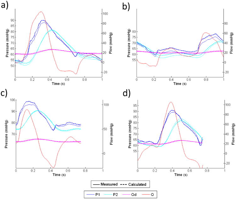
Fig 10. Comparisons Between Measured(solid lines) and Calculated(dashed lines) Pressure & Flow Waveforms for the Renal Impedance Module Under Four Different Flow Conditions: a) Flow Condition 1, b) Flow Condition 2, c) Flow Condition 3, and d) Flow Condition 4.
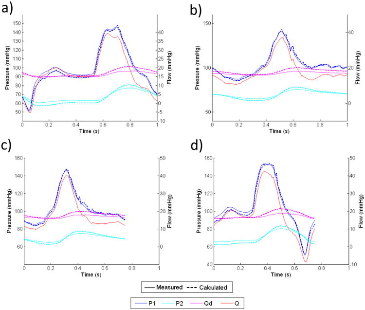
In both Figures 9 and 10, the flow waveforms show that much of the pulsatility in the input flow is absorbed by the capacitor, and the flow through the downstream resistor is fairly constant. This implies that for any given input flow waveform, the proximal resistor Rp needs to be able to accommodate the peak flow of the input waveform, where the downstream resistor Rd only needs to accommodate approximately the averaged flow of the input waveform.
By subtracting Qd from Q, we can calculate the flow into the capacitor, which then can be integrated to find the change in fluid volume inside the capacitor over each cardiac cycle. From calculations of pressure and volume with equation 15, we confirmed that the variation of capacitance value due to the volume change over each cardiac cycle is less than 3% from the reference value for both impedance modules.
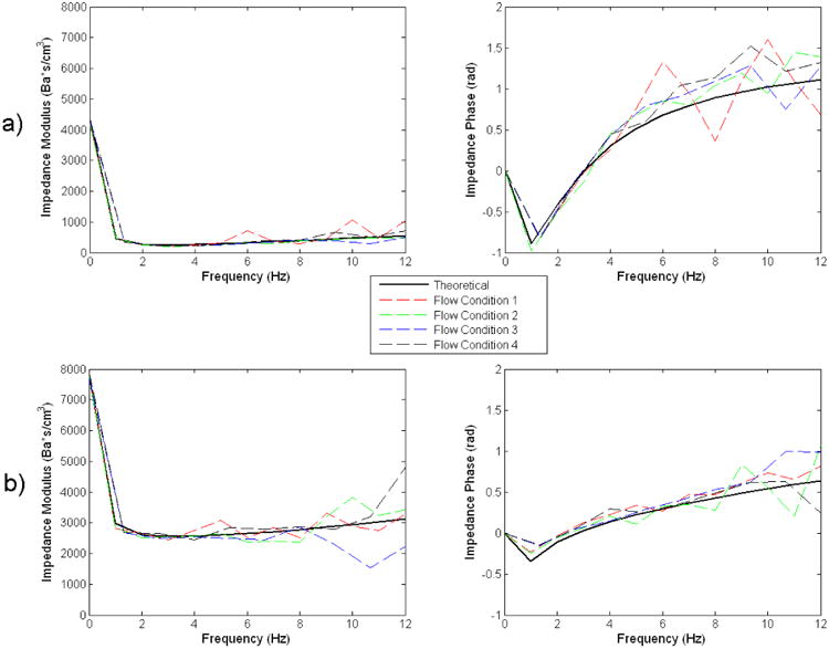
Fig 11 shows the impedance modulus and phase as derived from the analytical model, and as calculated from the four sets of experimental pressure and flow data for each module. For both impedance modules, there is close agreement between the theoretical impedance modulus & phase, and those determined from the experimental data of all of the four different flow conditions. This further shows that the impedance modules behave very consistently even when the flow conditions were changed. The general shapes and magnitudes of the impedance modulus and phase also compare well with those measured in-vivo in previous studies [7, 8, 10, 15].
Fig 11. Comparisons Between Theoretical and Experimental Flow Impedance Modulus and Phase for the a) Thoracic-aortic, and b) Renal, Impedance Module.
5. Conclusion
We showed that using the methods we presented, we can construct flow resistance units with stable resistance values over wide ranges of flow rates, which is a significant advancement from the common practice of using a partially closed valve to create flow resistances. The resistance value of the units we constructed can both be theoretically determined from construction details, and experimentally confirmed from pressure and flow measurements. We further showed that the impedance module assembled from individual resistor and capacitor components, performs very consistently across different flow conditions, and that the corresponding analytical model we described sufficiently captures the behavior of the physical system, faithfully representing flow and pressure relationships. When actually employing the physical Windkessel module in other experimental applications, whenever possible, flow and pressure data should be used to confirm or adjust the lumped component value assignments in the corresponding analytical model. We have shown that upon proper characterization of a particular impedance module, the analytical model can then accurately predict its behavior under different flow conditions.
In conclusion, the Windkessel impedance module we developed can be used as a practical tool for in-vitro cardiovascular studies. Implementing the Windkessel module in a physical setup enables the experimental system to replicate realistic blood pressures under physiologic flow conditions. The ability to construct in-vitro physical systems to mimic in-vivo conditions can aid in the direct physical testing of implantable cardiovascular medical devices such as stents and stent grafts, which require reliable knowledge of how the in-vivo forces and tissue motions will interact with the devices. In the area of CFD validation, well-characterized physical Windkessel modules connected to the outlets of a physical phantom will allow prescriptions of the same outlet boundary condition in the computational domain, such that the boundary condition prescription in-silico is representative of the physical reality. Furthermore, the ability to implement physiological impedances in-vitro enables experimental studies involving deformable materials to study the pulsatile motions of blood vessels, and wave propagations in the cardiovascular system, where re-producing realistic blood pressures is absolutely necessary for obtaining proper fluid-solid interactions. The work we presented here serves as a basis to contribute towards more rigorous cardiovascular in-vitro experimental studies in the future.
Acknowledgments
The authors would like to thank Chris Elkins for assistance with the flow experiments. This work was supported by the National Institutes of Health (Grants P50 HL083800, P41 RR09784, and U54 GM072970)
References
- 1.Vignon-Clementel IE, Figueroa CA, Jansen KE, Taylor CA. Outflow boundary conditions for three-dimensional finite element modeling of blood flow and pressure in arteries. Computer Methods in Applied Mechanics and Engineering. 2006;195(29-32):3776–96. doi: 10.1016/j.cma.2005.04.014. [DOI] [Google Scholar]
- 2.Grant BJ, Paradowski LJ. Characterization of pulmonary arterial input impedance with lumped parameter models. Am J Physiol. 1987;252(3 Pt 2):H585–93. doi: 10.1152/ajpheart.1987.252.3.H585. [DOI] [PubMed] [Google Scholar]
- 3.Krenz GS, Linehan JH, Dawson CA. A fractal continuum model of the pulmonary arterial tree. J Appl Physiol. 1992;72(6):2225–37. doi: 10.1152/jappl.1992.72.6.2225. [DOI] [PubMed] [Google Scholar]
- 4.Spilker RL, Feinstein JA, Parker DW, Reddy VM, Taylor CA. Morphometry-based impedance boundary conditions for patient-specific modeling of blood flow in pulmonary arteries. Ann Biomed Eng. 2007;35(4):546–59. doi: 10.1007/s10439-006-9240-3. [DOI] [PubMed] [Google Scholar]
- 5.Steele BN, Olufsen MS, Taylor CA. Fractal network model for simulating abdominal and lower extremity blood flow during resting and exercise conditions. Comput Methods Biomech Biomed Engin. 2007;10(1):39–51. doi: 10.1080/10255840601068638. doi:770213688[pii]10.1080/10255840601068638. [DOI] [PubMed] [Google Scholar]
- 6.Lagana K, Balossino R, Migliavacca F, Pennati G, Bove EL, de Leval MR, et al. Multiscale modeling of the cardiovascular system: Application to the study of pulmonary and coronary perfusions in the univentricular circulation. Journal of Biomechanics. 2005;38(5):1129–41. doi: 10.1016/j.jbiomech.2004.05.027. [DOI] [PubMed] [Google Scholar]
- 7.Segers P, Brimioulle S, Stergiopulos N, Westerhof N, Naeije R, Maggiorini M, et al. Pulmonary arterial compliance in dogs and pigs: The three-element windkessel model revisited. Am J Physiol. 1999;277(2 Pt 2):H725–31. doi: 10.1152/ajpheart.1999.277.2.H725. [DOI] [PubMed] [Google Scholar]
- 8.Stergiopulos N, Westerhof BE, Westerhof N. Total arterial inertance as the fourth element of the windkessel model. Am J Physiol. 1999;276(1 Pt 2):H81–8. doi: 10.1152/ajpheart.1999.276.1.H81. [DOI] [PubMed] [Google Scholar]
- 9.Wang JJ, Flewitt JA, Shrive NG, Parker KH, Tyberg JV. Systemic venous circulation. Waves propagating on a windkessel: Relation of arterial and venous windkessels to systemic vascular resistance. Am J Physiol Heart Circ Physiol. 2006;290(1):H154–62. doi: 10.1152/ajpheart.00494.2005. doi:00494.2005[pii]10.1152/ajpheart.00494.2005. [DOI] [PubMed] [Google Scholar]
- 10.Westerhof N, Lankhaar JW, Westerhof BE. The arterial windkessel. Med Biol Eng Comput. 2009;47(2):131–41. doi: 10.1007/s11517-008-0359-2. [DOI] [PubMed] [Google Scholar]
- 11.Lotz J, Meier C, Leppert A, Galanski M. Cardiovascular flow measurement with phase-contrast mr imaging: Basic facts and implementation. Radiographics. 2002;22(3):651–71. doi: 10.1148/radiographics.22.3.g02ma11651. [DOI] [PubMed] [Google Scholar]
- 12.Bax L, Bakker CJ, Klein WM, Blanken N, Beutler JJ, Mali WP. Renal blood flow measurements with use of phase-contrast magnetic resonance imaging: Normal values and reproducibility. J Vasc Interv Radiol. 2005;16(6):807–14. doi: 10.1097/01.RVI.0000161144.98350.28. doi:16/6/807[pii]10.1097/01.RVI.0000161144.98350.28. [DOI] [PubMed] [Google Scholar]
- 13.Greene ER, Venters MD, Avasthi PS, Conn RL, Jahnke RW. Noninvasive characterization of renal artery blood flow. Kidney Int. 1981;20(4):523–9. doi: 10.1038/ki.1981.171. [DOI] [PubMed] [Google Scholar]
- 14.Les AS, Shadden SC, Figueroa CA, Park JM, Tedesco MM, Herfkens RJ, et al. Quantification of hemodynamics in abdominal aortic aneurysms during rest and exercise using magnetic resonance imaging and computational fluid dynamics. Ann Biomed Eng. 38(4):1288–313. doi: 10.1007/s10439-010-9949-x. [DOI] [PMC free article] [PubMed] [Google Scholar]
- 15.Westerhof N, Elzinga G, Sipkema P. An artificial arterial system for pumping hearts. J Appl Physiol. 1971;31(5):776–81. doi: 10.1152/jappl.1971.31.5.776. [DOI] [PubMed] [Google Scholar]
- 16.Packomania Specht E. The best known packings of equal circles in the unit circle. University of Magdeburg; Germany: 2010. [Accessed May 5, 2010]. http://www.packomania.com/cci. [Google Scholar]
- 17.Khunatorn Y, Shandas R, DeGroff C, Mahalingam S. Comparison of in vitro velocity measurements in a scaled total cavopulmonary connection with computational predictions. Ann Biomed Eng. 2003;31(7):810–22. doi: 10.1114/1.1584684. [DOI] [PubMed] [Google Scholar]
- 18.Ku JP, Elkins CJ, Taylor CA. Comparison of cfd and mri flow and velocities in an in vitro large artery bypass graft model. Ann Biomed Eng. 2005;33(3):257–69. doi: 10.1007/s10439-005-1729-7. [DOI] [PubMed] [Google Scholar]


