Abstract
Surgeons using neuronavigation have realized the value of image guidance for feature recognition as well as for the precise application of surgical instruments. Recently, there has been a growing concern about the extent of intraoperative misregistration due to tissue deformation. Intraoperative imaging is currently under evaluation but limitations related to cost effectiveness and image clarity have made its wide spread adoption uncertain. As a result, computational model-guided techniques have generated considerable appeal as an alternative approach. In this paper, we report our initial experience with enhancing our brain deformation model by explicitly adding the falx cerebri. The simulations reported show significant differences in subsurface deformation with the falx serving to damp the communication of displacement between hemispheres by as much as 4 mm. Additionally, these calculations, based on a human clinical case, demonstrate that while cortical shift predictions correlate well with various forms of the model (70–80% of surface motion recaptured), substantial differences in subsurface deformation occurs suggesting that subsurface validation of model-guided techniques will be important for advancing this concept.
1 Introduction
The realization that intraoperative brain shift can misregister image-guided neuronavigation has generated significant interest in the surgical community. Studies of cortical surface shift during neurosurgery have reported movement on the order of 1 cm with a tendency for displacement to occur in the direction of gravity [1], [2], [3]. Early subsurface shift studies revealed substantial movement on the order of 4–7 mm during tumor resection cases [4]. Recently, Maurer et al. reported preliminary results using an interventional MR system to quantify subsurface movement and found significant variability from case to case suggesting that intraoperative motion is somewhat unpredictable based on the type of surgery alone [5]. Interestingly, they found significant shift due to gravity and that deformation across the midline was small indicating that the falx cerebri may play an important role. Clearly, the extent of deformation and mechanical support provided by anatomical anchor points needs to be studied further.
The emerging clinical experience suggests that intraoperative misregistration induced by tissue deformation is a significant problem. To date, solutions have been proposed using intraoperative MR and ultrasonography [6]–[11]. Intraoperative MR has the most appeal given its high resolution and excellent contrast but its expense and cumbersome implementation into the OR have raised some questions about its widespread adoption [6]–[8]. Co-registered ultrasonography overcomes these drawbacks but has poor image clarity which tends to degrade as surgery proceeds [9]–[11]. Alternatively, co-registered ultrasonography may serve an important role in correcting for misregistration when used in conjunction with other methods. The approach we are developing exploits sparsely available intraoperative data, i.e. ultrasonography and cortical surface measurements, in conjunction with a computational model of brain deformation to update preoperative images during surgery thus serving to enhance neuronavigational accuracy as well as realism [12].
To date, explicit modeling of the falx cerebri has been limited largely to the car crash environment [13] which is substantively different than the surgical counterpart, although some initial work has been performed here as well [14]. In this paper, we have taken a surgical case where significant gravity-induced shift was reported and added the anatomical constraint of the falx cerebri to improve the understanding of anatomical anchor points and their influence on subsurface tissue deformation distributions. The model calculations are compared to measurements of the cortical surface taken in the direction of gravity. Additionally, the calculations are compared to their homogeneous counterpart which has been presented elsewhere [15]
2 Methods
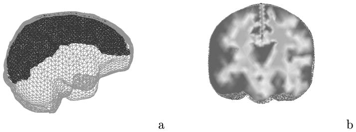
The computational geometry is derived from the preoperative MR series of the patient. Using AnalyzeAVW - Version 2.5, the brain and falx cerebri (approximate 2 mm width located between hemispheres) are segmented from the images and a discrete marching cubes algorithm is applied to create a surface boundary description of the extracted volumes [16]. The surface description is then used to generate a tetrahedral mesh [17]. Material heterogeneity is performed by calculating the average voxel intensity in an element and thresholding each tissue type based on the original MR series. Figure 1a is an illustration of the computational geometry with extra refinement about the falx cerebri. The mesh consisted of 25,340 nodes and 139,351 elements. Figure 1b depicts a nodally interpolated representation of the tissue element thresholding on a coronal cross-section in the mesh where the dark surrounding area represents gray matter, the lighter central area represents white matter, and the falx can be seen as the descending division between the hemispheres.
Fig. 1.

Computational representation of the brain: (a) finite element brain mesh with extra refinement about the falx cerebri; (b) element-based thresholding as a means of incorporating heterogeneity.
In previous work, we reported a detailed study measuring the displacement of cortical landmarks in 28 neurosurgical cases using an operating microscope and robotic platform [1]. This same technique was used to track a series of cortical landmarks in the direction of gravity for the clinical case presented in this paper.
3 Computational Model
We have chosen consolidation physics to represent deformation characteristics of the brain [18]. Consolidation describes the continuum as a biphasic medium with a solid matrix saturated with an interstitial fluid. When subjected to load, tissue experiences an instantaneous deformation at the contact area followed by subsequent deformation due to strain-induced hydrodynamic changes. The governing equation describing mechanical equilibrium is,
| (1) |
where G is the shear modulus ( where E is Young’s modulus), ν is Poisson’s ratio, α is the ratio of fluid volume extracted to volume change of tissue under compression, ε is the volumetric strain (ε = ∇ · u), ρt, ρf are the density of the tissue and surrounding fluid respectively, g is the gravitational acceleration vector, u is the displacement vector, and p is the interstitial pressure. Gravitational forces have been simulated as a difference in density between tissue and the surrounding fluid (elements above the resting level of cerebrospinal fluid post-craniotomy/drainage use the density of air for ρf).
A continuity equation relating volumetric strain to fluid drainage completes the description,
| (2) |
where k is the hydraulic conductivity, and 1/S is a void compressibility constant. We have adopted the convention assuming full saturation with an incompressible fluid (i.e. , α =1). The mathematical framework of coupled equations (1) and (2) has been previously reported in detail [19]. Model validation was performed using an in vivo experimental porcine model and demonstrated a 75–85% predictive capability of subsurface deformation [20].
In this paper a series of simulations were performed to understand the impact of the anatomical constraint of the falx cerebri on a real clinical case. The patient was brought to the OR for resection of tumor and surrounding epileptogenic cortex. The patient was supine with head turned 60 degrees to his right and secured in three-point fixation. The falx cerebri extends down between the hemispheres and is securely attached both anteriorly and posteriorly with the inner margin free to deform. In the first simulation considered, there is no special treatment of the falx and the tissue is assumed to be homogeneous. The second simulation (referred to as falx simulation 1) treats the falx as a structure with a stiffness approximately 6 times larger than that of the surrounding parenchymal tissue (Etissue = 2100 Pa, Efalx = 12000 Pa) where the nodes along the cortical surface of the falx are fixed. The last simulation (referred to as falx simulation 2) treats the falx as a rigid surface that allows brain tissue to slide (i.e. tangential motion) but not deform (i.e. normal motion) the falx. In all cases the level of cerebrospinal fluid is assumed to be slightly lower than the brain stem elevation when the head is rotated into its surgical orientation.
4 Results
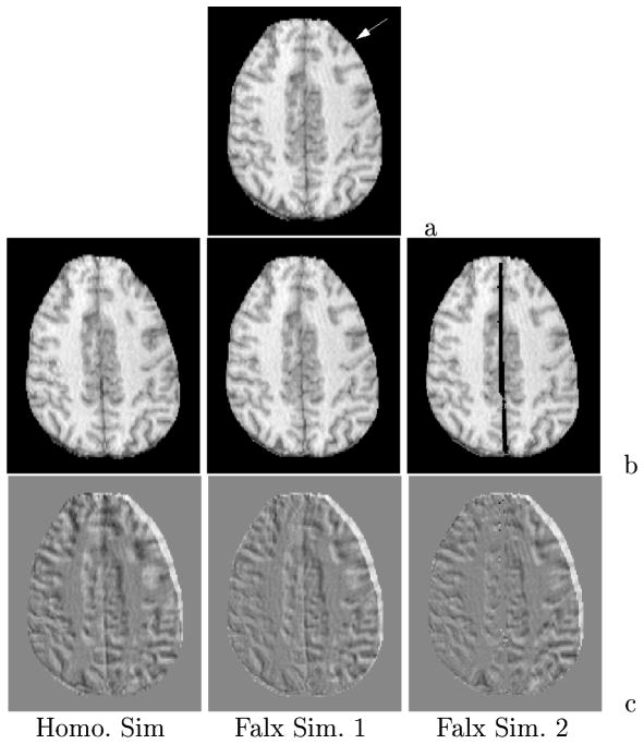
Figure 2 reports an axial cross section in the MR data set and the model-updated image counterparts for the three simulations with the top image showing the undeformed preoperative state and the direction of gravity (white arrow). The difference images highlight the amount of shift by the shading which differs from the background. Although not an exact measure due to out of plane motion, we can observe that falx simulation 1 (pinned falx at the cortical surface) has less motion than the homogeneous model at the interhemispheric fissure which is to be expected. However, simulation 1 does appear to have a small increase in deformation in the right posterior temporal section of the image. Falx simulation 2 also has increased temporal movement and seems to have less shift than falx simulation 1 in the contralateral hemisphere.
Fig. 2.
Deformed axial MR slice based on model simulations: (a) preoperative slice with gravity designated by white arrow, (b) slice generated from deformed image volume, (c) difference images with shades differing from background indicating shift.
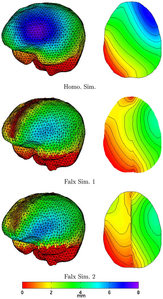
Further appreciation of these calculations can be found in Figure 3. Here, the total displacement of the cortical surface is shown on the left and the model cross-section corresponding to the MR slices in Figure 2 is shown on the right where the total displacement is color-coded. As can be anticipated, falx simulations 1 and 2 have less subsurface deformation which is undoubtedly caused by the rigid falx cerebri acting as a central support to the brain tissue. Also, the decrease in contralateral hemispheric motion indicated in Figure 2 is confirmed by the gradient shadings in Figure 3. Another interesting feature is that the area of maximal deformation has moved more temporally in both falx simulations which would explain the increased posterior temporal motion findings in Figure 2.
Fig. 3.
Cortical surface deformation distribution (left) and axial cross section equivalent to MR slice (right) showing total displacement for each simulation.
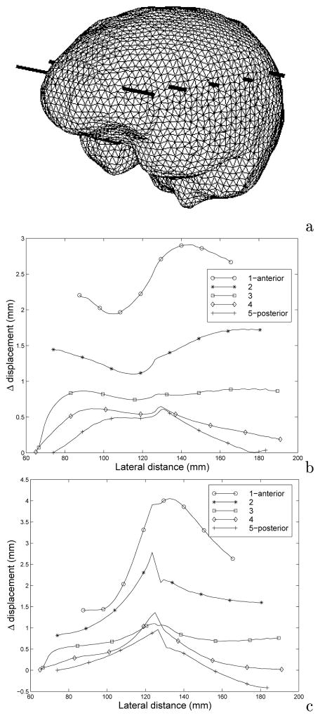
Figure 4 quantifies these changes in displacement between the falx simulation and the homogeneous model. Figure 4b and 4c shows the difference in total displacement along transects through the volume designated in Figure 4a (the largest lateral distance points correspond to the highest gravitational elevation along transect). Predominantly, the homogeneous model experienced more deformation than the falx counterpart (all positive values in Figures 4b and 4c correspond to larger movement by the homogeneous model). Additionally, we can see from Figures 4b and 4c that subsurface displacement can differ between the models by as much as 3 mm and 4 mm, respectively.
Fig. 4.
Total displacement distribution difference between homogeneous and falx simulations where the values of total displacement for each simulation is subtracted from the homogeneous counterpart at the same points along each transect: (a) brain mesh volume showing comparison transects; (b) difference calculation for falx simulation 1; (c) difference calculation for falx simulation 2. The largest lateral distance in (b) and (c) corresponds to highest elevations in the surgically positioned cranium.
Table 1 quantifies the comparison between model calculations and cortical surface measurements with respect to gravity. Also shown is a point by point percent recapture ( , where dm and dc are measured and calculated displacements, respectively) which estimates the amount of displacement recaptured by the model-guided technique that would have otherwise been added to misregistration error. Here, we see that all calculations qualitatively match the data well, however, falx simulation 1 appears to be the most satisfying in terms of surface data.
Table 1.
Comparison between measured and calculated shift with respect to gravity for all simulations.
| Point # | Measured Displ. mm | Homo. Sim Displ. mm (%recapture) | Falx Sim1 Displ. mm (%recapture) | Falx Sim2 Displ. mm (%recapture) |
|---|---|---|---|---|
|
| ||||
| 1 | 6.7 | 4.7 (70%) | 4.3 (64%) | 4.9 (73%) |
| 2 | 4.6 | 5.2 (87%) | 4.6 (100%) | 5.2 (87%) |
| 3 | 4.2 | 5.6 (67%) | 4.9 (83%) | 5.6 (67%) |
| 4 | 3.5 | 3.5 (100%) | 3.4 (97%) | 2.9 (83%) |
5 Discussion
Figure 2 highlights a decrease in contralateral motion illustrated by a decrease in shading differences above the background across the simulations which is confirmed by results observed in Figures 3 and 4. Figure 3 shows significant differences with respect to cortical movement, particularly in the hemisphere of surgical focus with the temporal migration of maximal deformation as well as the sharp change in total deformation in the region of the falx. Further, the gradient images shown in Figure 3 show significant differences in subsurface deformation with the falx serving to damp the communication of displacement between hemispheres. Figures 4b and 4c suggest that the falx cerebri could affect subsurface deformation in the region of surgical focus by as much as 3–4 mm. Table 1 indicates that small differences exist among cortical shift predictions, with all calculations recapturing approximately 70–80% of the gravity-induced motion. Interestingly, falx simulation 2 has less subsurface movement than simulation 1 when comparing Figure 4b and 4c, yet larger cortical surface movement in Table 1. Recall that simulation 2 has a rigid falx but the tissue is not bound to the falx per se, i.e. gravity can still move the tissue along the falx but because the falx is rigid, contralateral motion will still be inhibited. In falx simulation 1, the falx is part of the continuum and is pinned at the cortical surface (Figure 3, middle left shows a red zero displacement strip extending along the falx) which would undoubtedly dampen surface motion more than in the case of falx simulation 2 which is evident in the Figure 3 axial cross sections where falx simulation 2 has more displacement all along the upper left hemispheric surface.
6 Conclusions
The preliminary investigation reported by Maurer et al. provides impetus for understanding anatomical constraints intracranially and warrants more detailed experimental investigation using interventional imaging systems. The results shown here correlate with Maurer et al.’s initial interventional MR observations which noted that the deformation across the midline seemed to be damped significantly by the falx cerebri. Falx simulation 1 is the most satisfying with respect to cortical displacement measurements (Table 1). As noted in Figures 2–4, simulation 2 did appear to dampen more motion in the contralateral hemisphere resembling the Maurer et al. experience. However, we should note that the stiffness properties used in falx simulation 1 have not been investigated thoroughly and we could anticipate that properties stiffer than those used here may decrease displacement communication between hemispheres even further.
In any case, more detailed investigation needs to be conducted with respect to the stiffness properties as well as the hydrodynamic communication across the falx. Other support structures such as the tentorium cerebelli which supports the occipital lobes of the cerebral cortex as well as the cerebellum also need to be studied. Further, we can anticipate that with more detailed knowledge of anatomical support structures, the accuracy of our model-guided approach to neuronavigation will increase. In addition, the presence of support structures in the brain gives further credence to the possibility of reduced volume calculations which would significantly improve computational speed thus increasing the attractiveness of the model-updating approach.
Acknowledgments
This work was supported by National Institutes of Health grant R01-NS33900 awarded by the National Institute of Neurological Disorders and Stroke. ANALYZE software was provided in collaboration with the Mayo Foundation.
Contributor Information
Michael I. Miga, Email: michael.miga@dartmouth.edu.
Keith D. Paulsen, Email: keith.paulsen@dartmouth.edu.
Francis E. Kennedy, Email: francis.kennedy@dartmouth.edu.
Alex Hartov, Email: alex.hartov@dartmouth.edu.
David W. Roberts, Email: david.w.roberts@dartmouth.edu.
References
- 1.Roberts DW, Hartov A, Kennedy FE, Miga MI, Paulsen KD. Intraoperative brain shift and deformation: a quantitative clinical analysis of cortical displacements in 28 cases. Neurosurgery. 1998;43(4):749–760. doi: 10.1097/00006123-199810000-00010. [DOI] [PubMed] [Google Scholar]
- 2.Hill DLG, Maurer CR, Maciunas RJ, Barwise JA, Fitzpatrick JM, Wang MY. Measurement of intraoperative brain surface deformation under a craniotomy. Neurosurgery. 1998;43(3):514–528. doi: 10.1097/00006123-199809000-00066. [DOI] [PubMed] [Google Scholar]
- 3.Dorward NL, Olaf A, Velani B, Gerritsen FA, Harkness WFJ, Kitchen ND, Thomas DGT. Postimaging brain distortion: magnitude, correlates, and impact on neuronavigation. J Neurosurg. 1998;88:656–662. doi: 10.3171/jns.1998.88.4.0656. [DOI] [PubMed] [Google Scholar]
- 4.Dickhaus H, Ganser K, Staubert A, Bonsanto MM, Wirtz CR, Tronnier VM, Kunze S. Quantification of brain shift effects by MR-imaging. Proc An Int Conf IEEE Eng Med Biology Soc. 1997:491–494. [PubMed] [Google Scholar]
- 5.Maurer CR, Hill DLG, Martin AJ, Liu H, McCue M, Rueckert D, Lloret D, Hall WA, Maxwell RE, Hawkes DJ, Truwit CL. Investigation of intraoperative brain deformation using a 1.5-T interventional MR system: Preliminary Results. IEEE Transactions on Medical Imaging. 1998;17(5):817–825. doi: 10.1109/42.736050. [DOI] [PubMed] [Google Scholar]
- 6.Moriarty TM, Kikinis R, Jolesz FA, Black PM, Alexander E., 3rd Magnetic resonance imaging therapy. Intraoperative MR imaging. Neurosurg Clin N Am. 1996;7:323–331. [PubMed] [Google Scholar]
- 7.Wirtz CR, Bonsanto MM, Knauth M, Tronnier VM, Albert FK, Staubert A, Kunze S. Intraoperative magnetic resonance imaging to update interactive navigation in neurosurgery: Method and preliminary experience. Computer Aided Surgery. 1997;2:172–179. [PubMed] [Google Scholar]
- 8.Steinmeier R, Fahlbusch R, Ganslandt O, Nimsky C, Buchfelder M, Kaus M, Heigl T, Lenz G, Kuth R, Huk W. Intraoperative magnetic resonance imaging with the Magnetom open scanner: concepts, neurosurgical indications, and procedures: a preliminary report. Neurosurgery. 1998;43(4):739–748. doi: 10.1097/00006123-199810000-00005. [DOI] [PubMed] [Google Scholar]
- 9.Trobaugh JW, Richard WD, Smith KR, Bucholz RD. Frameless stereotactic ultrasonography: Methods and applications. Computerized Medical Imaging and Graphics. 1994;18(4):235–246. doi: 10.1016/0895-6111(94)90048-5. [DOI] [PubMed] [Google Scholar]
- 10.Comeau RM, Fenster A, Peters TM. Intraoperative US in interactive image-guided neurosurgery. Radiographics. 1998;19(4):1019–1027. doi: 10.1148/radiographics.18.4.9672984. [DOI] [PubMed] [Google Scholar]
- 11.Hartov A, Eisner SD, Roberts DW, Paulsen KD, Platenik LA, Miga MI. Error analysis for a free-hand three-dimensional ultrasound system for neuronavigation. Neurosurgical Focus. 1999;6(3):art 5. [Google Scholar]
- 12.Roberts DW, Miga MI, Hartov A, Eisner S, Lemery J, Kennedy FE, Paulsen KD. Intraoperatively updated neuroimaging using brain modeling and sparse data. Neurosurgery. 1999 submitted. [PubMed] [Google Scholar]
- 13.Nishimoto T, Murakami S. Relation between diffuse axonal injury and internal head structures on blunt impact. ASME Journal of Biomechanical Engineering. 1998;120(1):140–147. doi: 10.1115/1.2834294. [DOI] [PubMed] [Google Scholar]
- 14.Schill M, Schinkman M, Bender HJ, Manner R. Biomechanical simulation of the falx cerebri using the finite element method. Conference Proceedings to the 1996 IEEE Engineering in Medicine and Biology 18th Annual International Conference; Amsterdam, The Netherlands. 1996. pp. 455–456. [Google Scholar]
- 15.Miga MI, Paulsen KD, Kennedy FE, Hoopes PJ, Hartov A, Roberts DW. Model-updated image guidance: Initial clinical experience with gravity-induced brain deformation. IEEE Transactions on Medical Imaging. 1999 doi: 10.1109/42.811265. accepted. [DOI] [PubMed] [Google Scholar]
- 16.Schroeder W, Martin K, Lorensen B. The Visualization Toolkit: An Object-Oriented Approach to 3D Graphics. Prentice Hall; New Jersey: 1996. [Google Scholar]
- 17.Sullivan JM, Jr, Charron G, Paulsen KD. A three dimensional mesh generator for arbitrary multiple material domains. Finite Element Analysis and Design. 1997;25:219–241. [Google Scholar]
- 18.Biot M. General theory of three dimensional consolidation. J Appl Phys. 1941;12:155–164. [Google Scholar]
- 19.Paulsen KD, Miga MI, Kennedy FE, Hoopes PJ, Hartov A, Roberts DW. A computational model for tracking subsurface tissue deformation during stereotactic neurosurgery. IEEE Transactions on Biomedical Engineering. 1999;46(2):213–225. doi: 10.1109/10.740884. [DOI] [PubMed] [Google Scholar]
- 20.Miga MI, Paulsen KD, Kennedy FE, Hoopes PJ, Hartov A, Roberts DW. In vivo quantification of a homogeneous brain deformation model for updating preoperative images during surgery. IEEE Transactions on Biomedical Engineering. 1999 doi: 10.1109/10.821778. in press. [DOI] [PubMed] [Google Scholar]


