Abstract
A novel brain shift tracking protocol is introduced in this paper which utilizes laser range scan (LRS) data and 2D deformable image registration. This protocol builds on previous efforts to incorporate intra-operative LRS data into a model-updated image guided surgery paradigm for brain shift compensation. The shift tracking method employs the use of a LRS system capable of capturing textures of the intra-operative scene during range data acquisition. Textures from serial range images are then registered using a 2D deformable registration approach that uses local support radial basis functions and mutual information. Given the deformation field provided by the registration, 3D points in serial LRS datasets can then be tracked. Results from this paper indicate that the error associated with tracking brain movement is 1.1mm on average given brain shifts of approximately 20.5mm. Equally important, a strategy is presented to rapidly acquire intra-operative measurements of shift which are compatible with model-based strategies for brain deformation compensation.
1 Introduction
Current image guided procedures (IGP) proceed with a rigid registration of the patient to their patient-specific pre-operative image sets using fiducials. Recent literature has shown that this protocol for IGP may lead to inaccuracies related to the shifting of the brain during surgery [1]. As a result, there is substantial rationale in current IGP research to measure, track, and compensate for brain shift.
There are two emergent compensation strategies for the brain shift problem in IGP. The first strategy is to use intra-operative imaging during surgery to capture and account for brain shift. Modalities such as intra-operative CT, intra-operative MR and intra-operative US have been, or are being, investigated as image-based compensation strategies [2,3,4]. However, unique challenges in each of these modalities have limited their widespread adoption as the de facto brain shift compensation strategy.
An alternative strategy to compensate for brain shift is to use computational models and sparse intra-operative data to correct for deformation during surgery [5]. In this paradigm, a physical or statistical model of brain shift is driven with sparse data (i.e. data with limited intra-operative extent or information) to accurately deform pre-operative images to their intra-operative position. By definition, this method has the advantage of incorporating all forms of spatially-encoded pre-operative data (positron emission tomography, functional MR, etc.). This is not the case with intra-operative imaging methods which only provide data associated with the particular imaging modality (MR, CT or US,). Furthermore, computational methods for shift compensation are effective [6] and have minimal logistical constraints for intra-operative use.
For successful deployment of a model-based shift compensation strategy, some quantitative information regarding brain deformation is necessary to constrain model calculations. Many intra-operative data acquisition devices exist for this purpose [7][8][9], however, in this paper laser-range scanning is used as the data acquisition system. Laser range scanning provides a relatively inexpensive, time-efficient, non-contact method of surface data acquisition.
Once the intra-operative data has been acquired, an effective method of incorporating this data into the computational model must be developed. In previous reports [10], a rigid registration approach was developed to align the intra-operative range scan data to pre-operative image-sets. In this paper, a deformable registration extension is explored to allow for shift tracking based on serial laser-range scan data. The deformable registration is provided by local support radial basis functions [11] and mutual information optimization [12]. Once calculated, the deformation field allows for easy calculation of surface shift in serial range scans. The result of this shift tracking can then be used as driving conditions within a computational framework for model-updated image guided neurosurgery.
2 Methods
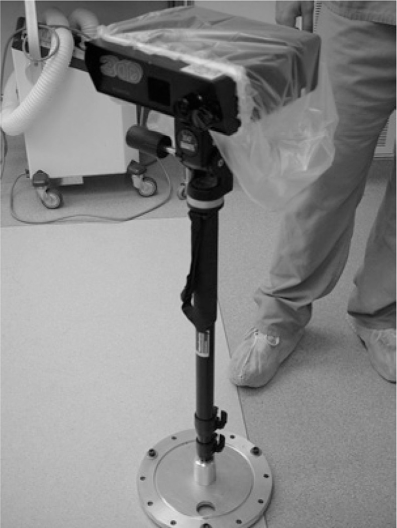
For range data acquisition, a laser-range scanning device is used (RealScan3D USB, 3D Digital Corp, Bethel, CT, USA). The scanner (Figure 1) is mounted on a vibration-damped monopod that is brought into and out of the surgical field-of-view (SFOV) manually. A thorough discussion of the range scanner can be found in [13]. After dural opening, the monopod and scanner are brought into the SFOV and the laser scanning extents (left and right margins) are calibrated to cover the width of the craniotomy. A laser stripe is then passed over the brain’s surface and range data is collected using the principle of optical triangulation. After acquisition, the scanner and monopod are moved out of the SFOV. The entire data acquisition process adds approximately 1.5 minutes per scan to the operating time and has been approved for clinical use by the Vanderbilt University IRB (VUIRB).
Fig. 1.
Laser range scanner mounted on vibration damping monopod in OR.
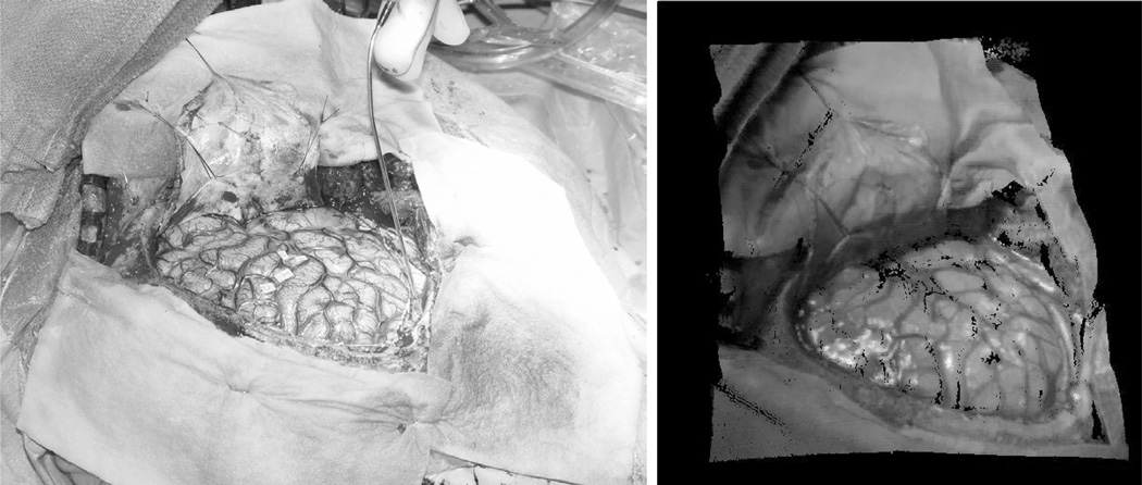
A unique feature of the scanner is that it reports texture map coordinates that allow for intensity values to be assigned to the range points. For this process, an RGB bitmap is captured at the time of scanning. Texture map coordinates are generated given a manufacturer calibration of range space to texture space. The coordinates can then be used to generate textured point clouds of the SFOV. An example SFOV with its corresponding textured LRS data is shown in Figure 2.
Fig. 2.
A digital photograph is shown on the left with the corresponding textured range scan data on the right.
For the shift tracking algorithm, serial LRS datasets are registered to each other via deformable 2D image registration. The registration process occurs entirely in texture space. Textures from serial range scans are, first, rigidly registered using mutual information methods that optimize a rigid 2D transformation. Local support radial basis functions are then used to register the images in a deformable fashion that optimizes the mutual information between the two textures. Furthermore, each LRS acquisition acquires a unique depth map associated with each texture; hence, the non-rigid registration of the texture images provides correspondence between these two unique depth maps and ultimately results in a distinct three-dimensional trajectory for each point.
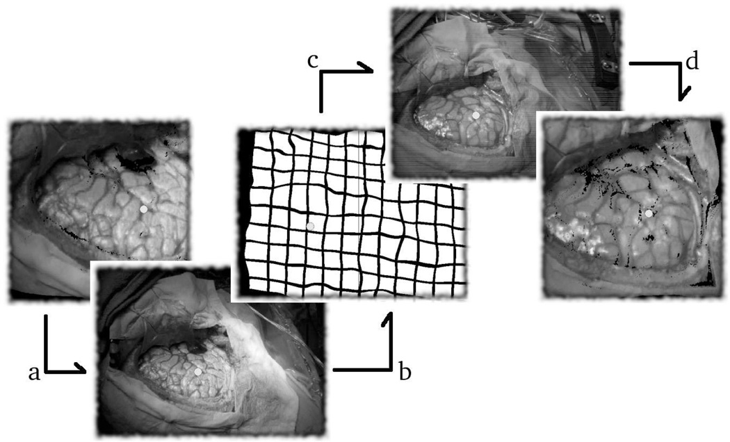
Once the deformation field between the two textures is known, shift between serial LRS datasets can be calculated. For this process, a target point is selected in one of the two serial datasets, and is transformed into texture space using its texture coordinates (Figure 3(a)). The transformed point is then deformed into the second texture space (Figure 3(b & c)) and projected back into the 3D space of the second LRS dataset, 3(d). Using this method, the motion of a point, in a single LRS dataset can be tracked in three dimensions through serial LRS datasets.
Fig. 3.
A schematic outlining the deformable registration process. The point of interest is shown transformed into its texture space in (a). The same point shown deformable transformed into a serial texture space in (b) and (c). Finally, the point is projected back into the three dimensional space of the second LRS dataset in (d).
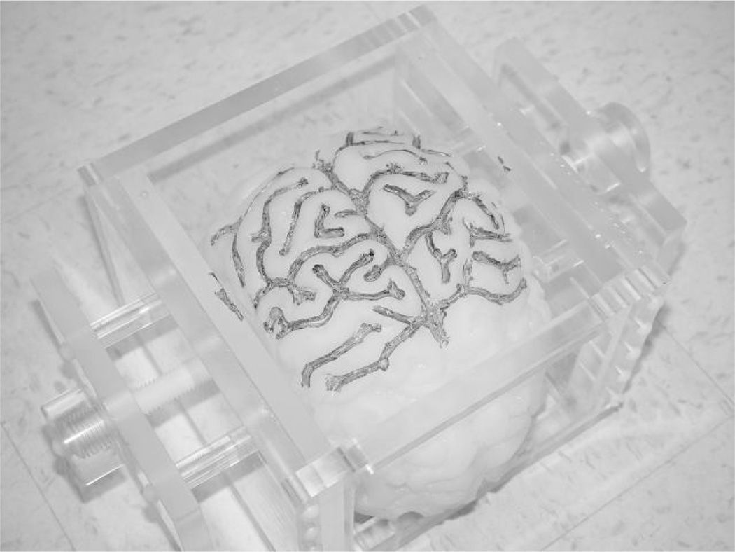
In this paper, we demonstrate the shift tracking protocol in a phantom experiment and on a single in vivo case. A silicon impression of a cortical surface mold, with the sulcal grooves artificially highlighted (see Figure 4), was used as the scanning phantom. The phantom was scanned three times (in three different poses) while in a deformation apparatus: undeformed, compression applied to one side, and compression applied to both sides. For each pose, physical-space locations for surface landmarks were acquired using an OPTOTRAK 3020 (Northern Digital Inc, www.ndigital.com) localization system. Deformation magnitudes were calculated for corresponding landmarks between the undeformed pose and each deformed pose. Similar magnitudes for the same points were calculated in LRS-space by the automated shift tracking protocol. Absolute magnitude differences between physical-space and LRS-space were calculated as a measure of shift-tracking accuracy relative to the “ground-truth” shift observed in physical-space.
Fig. 4.
Silicon phantom and deformation chamber used for validation studies.
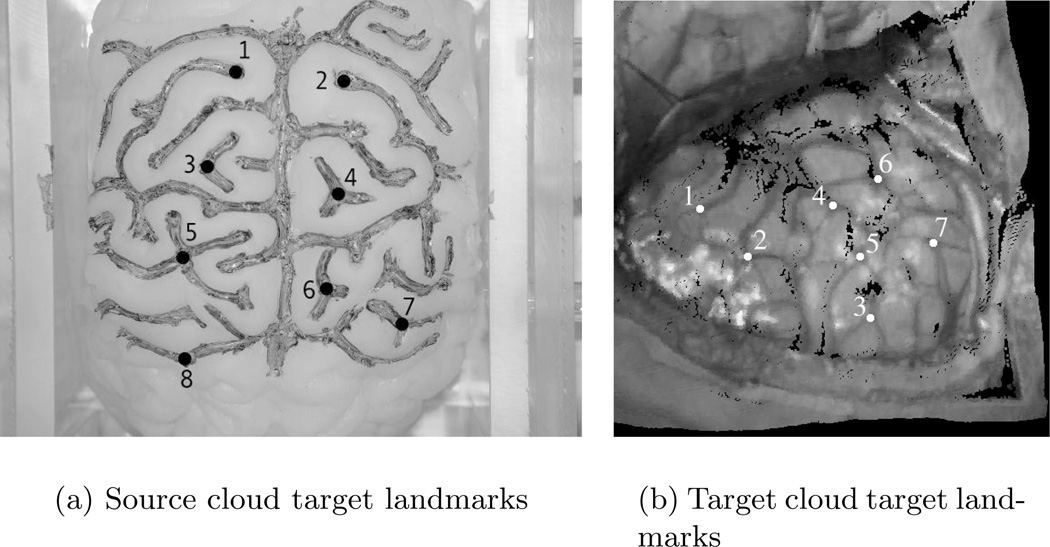
The in vivo case was provided by a consenting patient undergoing cortical resection therapy and acquired according to the guidelines of the VUIRB approved acquisition procedure. To test the accuracy of the shift tracking protocol in the in vivo case, corresponding points in the source and target LRS data were selected manually.1 The source landmarks (see Figure 5) were then registered to the target cloud as per the shift tracking protocol. Shift tracking error (STE) was calculated as the residual distance between the manually selected position of the landmarks in target cloud space and the registered position, i.e. Equation 1.
| (1) |
where, STE is the shift tracking error, xj is a manually localized point in the target LRS data, and T(yj) is the corresponding point in source LRS data deformably transformed into target cloud space. STEs for the targets are reported in this paper along with the mean STE for all points.
Fig. 5.
Landmarks used in the phantom and in vivo cloud for shift tracking error assessment.
3 Results
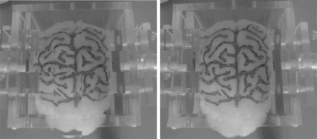
Figure 6 shows an example result of the deformable registration on the phantom. The numerical data associated with the correlation study between shift in LRS-space and physical-space are listed in Table 1. In registering both deformed poses to the undeformed pose, the calculated shift was not statistically different when compared to the shift observed in physical-space (unpaired t-test, equal variances: p(T ≤ t) = 0.55 and p(T ≤ t) = 0.68 for the one- and two-sided compressions, respectively). The tracking efficiencies, as defined by Equation 2, were 92.52 % and 92.22 % for the one- and two-sided compressions, respectively.
| (2) |
where TE is the tracking efficiency, is the mean value of the initial deformation, and ε̅ is the mean error between experimental displacement and the displacement provided by the shift-tracking protocol (values can be found in the last row of Table 1).
Fig. 6.
Example deformable registration results using the phantom textures. The results are presented using checkerboard images of the pre-registered (left) and post-registered (right) views.
Table 1.
Phantom shift tracking experiment results. ε represents the difference in magnitudes of shift observed in physical-space and shift calculated via the shift-tracking protocol. Initial deformation magnitudes (dexp) are reported from the physical-space measurements provided by the OPTOTRAK system.
| One-sided compression | Two-sided compression | |||
|---|---|---|---|---|
| Landmark # | dexp (mm) | ε (mm) | dexp (mm) | ε (mm) |
| 1 | 9.11 | 1.61 | 7.64 | 0.91 |
| 2 | 6.87 | 0.11 | 5.81 | 1.06 |
| 3 | 8.35 | 0.08 | 7.65 | 0.65 |
| 4 | 6.43 | 0.08 | 6.06 | 0.83 |
| 5 | 9.63 | 1.10 | 7.91 | 0.07 |
| 6 | 6.96 | 0.56 | 6.87 | 0.51 |
| 7 | 8.44 | 0.97 | 6.02 | 0.10 |
| 8 | 10.43 | 0.31 | 7.48 | 0.27 |
| Mean±SD | 8.03±1.58 | 0.60±0.57 | 7.07±1.27 | 0.55±0.38 |
The numerical data corresponding to the landmark tracking experiment for the in vivo case are given in Table 2. The STE and initial deformation for this case are significantly different (p(T ≤ t) < 0.05).
Table 2.
Shift tracking errors for the in vivo case. dexp represents the shift calculated by manually localizing corresponding points in each the serial LRS datasets. The shift tracking error (as defined by Eq. 1) represents the difference in localized position to registered position.
| Landmarks # | dexp (mm) | STE (mm) |
|---|---|---|
| 1 | 21.94 | 0.53 |
| 2 | 20.28 | 1.69 |
| 3 | 18.14 | 1.03 |
| 4 | 22.76 | 1.41 |
| 5 | 18.85 | 1.06 |
| 6 | 22.33 | 1.27 |
| 7 | 19.35 | 0.51 |
| Mean±SD | 20.524±1.84 | 1.07±0.44 |
4 Discussion
For both phantom and in vivo experiments, the results show that the shift tracking protocol outlined in this paper can effectively characterize landmark motion through serial LRS datasets. In the phantom experiments, the controlled data acquisition and comparison to independent measurements provided by the OPTOTRAK system provides insight into the method’s ability to account for pure deformation (i.e. scanner was stationary during all acquisitions). Furthermore, the statistical analysis (t-test) results, imply that the shifts calculated algorithmically obey shift characteristics observed physically.
In the in vivo case, the results demonstrate that the shift-tracking protocol can measure large scale shifts on clinical data. Additionally, a distinct strength to the approach was the ability to register large scale rigid-body motion. Specifically, the results reflected in Table 2 demonstrate effective shift tracking in the midst of large positional changes in the camera (since the magnitudes of shift in Table 2 reflect rigid body motions of the camera as well as deformations of the brain surface). Although, the delineation of deformation from rigid body motion cannot be made in this clinical case (i.e. the scanner was not tracked in physical-space), the results do indicate feasibility of this approach on clinical data. This claim is supported by the low mean and standard deviations seen in the STE’s of the in vivo case.
5 Conclusions
The methods and results of this paper outline a novel and efficient method for cortical shift tracking that is amenable to a model-based approach to shift compensation. The deformable registration approach allows for the tracking of manually localized points on the brain surface using 2D deformable registration techniques and intra-operative SFOV textures. The viability of the LRS as an intra-operative data acquisition device is enhanced given the preliminary shift tracking results presented in this paper. Future work regarding the methods outlined in this paper include more validation studies on phantoms and in vivo datasets. Nonetheless, the results presented within this paper provide a critical step in the development of model-based methods for correcting brain deformations within IGS.
Acknowledgements
Financial support provided by the Vanderbilt Discovery Grant program.
Footnotes
The tracked points were localized three times for each LRS dataset and averaged to minimize uniform noise in the localization.
Contributor Information
Tuhin K. Sinha, Email: tk.sinha@vanderbilt.edu.
Valerie Duay, Email: valerie.duay@vanderbilt.edu.
Benoit M. Dawant, Email: benoit.dawant@vanderbilt.edu.
Michael I. Miga, Email: michael.i.miga@vanderbilt.edu.
References
- 1.Nauta HJ. Error assessment during “image guided” and “imaging interactive” stereotactic surgery. Comp. Med. Img. and Graph. 1994;18:279–287. doi: 10.1016/0895-6111(94)90052-3. [DOI] [PubMed] [Google Scholar]
- 2.Lunsford LD, Martinez AJ. Stereotactic exploration of the brain in the era of computed tomography. Surgical Neurology. 1984;22:222–230. doi: 10.1016/0090-3019(84)90003-x. [DOI] [PubMed] [Google Scholar]
- 3.Nabavi A, et al. Image-guided therapy and intraoperative mri in neurosurgery. Min. Inv. Thpy. and All. Tech. 2000;9:277–286. doi: 10.1080/13645700009169658. [DOI] [PubMed] [Google Scholar]
- 4.Gobbi DG, Comeau RM, Peters TM. LNCS: MICCAI ’00. Vol. 1935. Springer-Verlag; 2000. Ultrasound/mri overlay with image warping for neurosurgery; pp. 106–114. [Google Scholar]
- 5.Roberts DW, Miga MI, Hartov A, Eisner S, Lemery JM, Kennedy FE, Paulsen KD. Intraoperatively updated neuroimaging using brain modeling and sparse data. Neurosurgery. 1999;45:1199–1206. [PubMed] [Google Scholar]
- 6.Miga MI, Paulsen KD, Hoopes PJ, Kennedy FE, Hartov A, Roberts DW. In vivo quantification of a homogeneous brain deformation model for updating preoperative images during surgery. IEEE TBME. 2000;47:266–273. doi: 10.1109/10.821778. [DOI] [PubMed] [Google Scholar]
- 7.Galloway RL, Macuinas RJ, Bass WA, Carpini W. Optical localization for interactive, Image-Guided Neurosurgery. Medical Imaging. 1994;2164:137–145. [Google Scholar]
- 8.Bucholz RD, Yeh DD, Trobaugh J, McDurmont LL, Sturm CD, Baumann C, Henderson JM, Levy A, Kessman P. LNCS: CVRMED-MRCAS ’97. Vol. 1205. Springer-Verlag; 1997. The correction of stereotactic inaccuracy caused by brain shift using an intraoperative ultrasound device; pp. 459–466. [Google Scholar]
- 9.Herline A, et al. Technical advances toward interactive image-guided laparoscopic surgery. Surg. End.-US and Int. Tech. 2000;14:675–679. doi: 10.1007/s004640000023. [DOI] [PubMed] [Google Scholar]
- 10.Sinha TK, Cash DM, Weil RJ, Galloway RL, Miga MI. LNCS: MICCAI ’02. Vol. 2489. Springer-Verlag; 2002. Cortical Surface Registration Using Texture Mapped Point Clouds and Mutual Information. [Google Scholar]
- 11.Rodhe G, Aldroubi A, Dawant B. The Adaptive Bases Algorithm for Intensity Based Non Rigid Image Registration. (IEEE TMI) doi: 10.1109/TMI.2003.819299. In Press. [DOI] [PubMed] [Google Scholar]
- 12.Wells WM, Viola P, Atsumi H, Nakajima S, Kikinis R. Multi-modal volume registration by maximization of mutual information. Medical Image Analysis. 1996;1:35–51. doi: 10.1016/s1361-8415(01)80004-9. [DOI] [PubMed] [Google Scholar]
- 13.Miga MI, Sinha TK, Cash DM, Galloway RL, Weil RJ. Cortical surface registration for image-guided neurosurgery using laser range scanning. IEEE Transactions in Medical Imaging. 2003 doi: 10.1109/TMI.2003.815868. In press. [DOI] [PMC free article] [PubMed] [Google Scholar]


