Abstract
Cavitation and bubble dynamics have a wide range of practical applications in a range of disciplines, including hydraulic, mechanical and naval engineering, oil exploration, clinical medicine and sonochemistry. However, this paper focuses on how a fundamental concept, the Kelvin impulse, can provide practical insights into engineering and industrial design problems. The pathway is provided through physical insight, idealized experiments and enhancing the accuracy and interpretation of the computation. In 1966, Benjamin and Ellis made a number of important statements relating to the use of the Kelvin impulse in cavitation and bubble dynamics, one of these being ‘One should always reason in terms of the Kelvin impulse, not in terms of the fluid momentum…’. We revisit part of this paper, developing the Kelvin impulse from first principles, using it, not only as a check on advanced computations (for which it was first used!), but also to provide greater physical insights into cavitation bubble dynamics near boundaries (rigid, potential free surface, two-fluid interface, flexible surface and axisymmetric stagnation point flow) and to provide predictions on different types of bubble collapse behaviour, later compared against experiments. The paper concludes with two recent studies involving (i) the direction of the jet formation in a cavitation bubble close to a rigid boundary in the presence of high-intensity ultrasound propagated parallel to the surface and (ii) the study of a ‘paradigm bubble model’ for the collapse of a translating spherical bubble, sometimes leading to a constant velocity high-speed jet, known as the Longuet-Higgins jet.
Keywords: cavitation, bubble dynamics, fluid mechanics
1. Introduction
Engineering and industrial design is highly dependent on computational modelling of the ‘device’, but theory can also provide deeper physical and scientific insights into the development of the model: criteria to be met, both old and new phenomena to be predicted and opportunities for new insights. The principal objective is to show how an approach based on the Kelvin impulse can provide valuable insights from its origins as a mathematical development, to providing physical understanding, potentially simple experiments (in a relative sense) to test the theory as well as providing checks and balances on the computation. From these more elementary studies, an improved collective understanding can be developed; ranges of physical space to be exploited can be obtained or avoided; new experiments designed leading to better or new ‘devices’. Figure 1 is used to emphasize and highlight some of the links from which the ‘inner disc’ of computational and experimental studies flow to the ‘outer rings’ of opportunities.
Figure 1.
The wheel shows the links between fundamental developments in different areas of science, engineering and medicine, through engineering and industrial design, to practical applications. (Online version in colour.)
The Kelvin impulse is an enormously valuable concept in the area of unsteady cavitation bubble dynamics. It is related to the concept of momentum, but its advantage is the theory can be exploited to handle deformable surfaces such as bubbles and allowing the further facilitation of change from simply-connected to multiply-connected geometries (and vice versa), as frequently occurs with bubbles. The concept of the Kelvin impulse has its analogues and developments from particle mechanics, generalized to allow for changes in mass and momentum from one instant to the next, or more particularly in the case of cavitation bubble dynamics, ‘added mass’. In the development of the theory, the consideration of the conservation of momentum is an unbounded medium great care needs to be taken with the theoretical handling of the potential indefinite nature of the Kelvin impulse [1–4]. This paper repeats the classic analysis of Wu [4] for an infinite fluid to help clarify the ideas of earlier authors regarding the potential indefinite nature of the Kelvin impulse and is further extended to consider a semi-infinite fluid [5].
The subject of the ‘impulse’ in fluid mechanics, and more particularly the Kelvin impulse, has attracted attention throughout the theoretical development of fluid mechanics. For example, Lamb [6] made a number of comments about the impulse, stating ‘whatever the motion of a solid and fluid at any instant, it might be generated instantaneously from rest by a properly adjusted impulsive wrench’. This was followed with further statements of ‘the wrench is in fact that which would be required to counteract the impulsive pressure on the surface’, while later referring further to the contributions of Kelvin by saying ‘Kelvin called this the ‘impulse’ of the system under consideration’. Referring to the earlier quotations from Benjamin & Ellis [2], we add a further observation ‘…again if the liquid remained simply connected as the cavity closed up, the Kelvin impulse would have to vanish, which we cannot allow in the absence of an external retarding force. Thus, the cavity must deform in such a way as to make the liquid multiply connected—circulation can then appear in the liquid and we are left in the limit with a vortex system possessing the original Kelvin impulse’.
A further observation in the Benjamin & Ellis [2] paper was ‘an experimental fact, perhaps significant in this regard, is that cavitation damage induced by flow is often most severe in the neighbourhood of stagnation points downstream from the low pressure zone…’. This paper revisits many of the observations made by Benjamin & Ellis [2] exploring the use of the Kelvin impulse to provide insights and understanding to a range of experimental studies in cavitation bubble dynamics.
2. The momentum theorem in a perfect fluid
2.1. Infinite fluid
D'Alembert's paradox does not need to hold for deformable bodies, including bubbles, for unsteady motion in a perfect fluid. This is of fundamental interest in the area of cavitation bubble dynamics in which D'Alembert's paradox can be modified to account for the deformation of a bubble in a cavitating flow and an understanding of the physical outcomes of a bubble if it were to become multiply-connected with the generation of a circulation around the bubble. The theory developed in this section is based on the paper of Wu [4], with insights being gained from the studies of Benjamin & Ellis [2] and Saffman [3]. Consider the motion of a bubble in a perfect fluid (incompressible and inviscid) whose surface is defined by
| 2.1 |
such that the boundary condition on S(x, t) = 0 is given by
| 2.2 |
where n is the outward normal to the flow (in the case of a bubble, n will be directed into the bubble interior; figure 2a), U(x, t) the local surface velocity and ϕ the velocity potential. The surface S(x, t) is sufficiently continuous and differential such that
| 2.3 |
where  We also suppose the far-field potential may be written as follows:
| 2.4 |
where m(t) is the net source strength equal to the volume flux at the bubble surface, given by
| 2.5 |
and V(t) is the time-dependent bubble volume with d the vector dipole strength.
Figure 2.
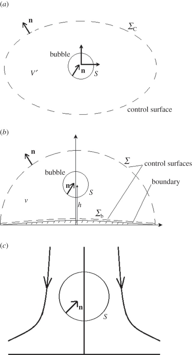
Modelling geometries for a bubble with notation in an (a) infinite fluid, (b) semi-infinite fluid and (c) forward stagnation point flow.
The linear momentum P of a constant density liquid ρ in a volume V′, surface S′ consisting of the union of the bubble surface S and a control surface ΣC (figure 2a) is given by
| 2.6a |
| 2.6b |
We write the fluid momentum P as the sum of two integrals
| 2.6c |
In the case of a cavitation bubble, where the bubble can change its volume rapidly, the potential will have a source-like behaviour, with the leading term in ϕ being inversely proportional to distance, as indicated in (2.4). Given that the area element in  is O(r2) and with ϕ being O(1/r), this may lead to a divergent integral. The solution to this dilemma is to consider the rate of change on momentum in the (for now) finite volume V′ which is equal to the force acting on the fluid at the external boundaries (i.e. S and ΣC) and owing to a buoyancy force [7]
| 2.7a |
where FS and  are the hydrodynamic force acting on the bubble S and control surface ΣC, respectively, and FB is the buoyancy force. On omitting the buoyancy force given by FB = ρgV(t), and concentrating solely on surface forces, we obtain
| 2.7b |
By rearranging (2.6c) and (2.7b), we obtain
| 2.8 |
by using the time derivative dIΣ/dt and the Bernoulli pressure condition for unsteady potential flow. If we let the control surface ΣC extend to infinity, this integral vanishes leaving
| 2.9 |
Note if the pressure inside the bubble is at most a function of time, then
| 2.10 |
the initial Kelvin impulse. If we assume the vapour/gas mixture density is effectively zero, we obtain, on integration from an initial state of rest
| 2.11 |
This is relevant to the earlier discussion in the Introduction about Lamb's [6] reference to an impulsive ‘wrench’ and impulsive pressure on (in this case) the bubble surface. The term on the r.h.s. of (2.11) is known as the Kelvin impulse, defined (on dropping the subscript S) as
| 2.12 |
The Kelvin impulse is of inestimable value in understanding cavitation and bubble dynamics. Of course in the absence of any external force (e.g. gravity), the time integral in (2.11) vanishes yielding I = I0. If we were to use the Green formula
| 2.13 |
where R = |x − x′| is the distance between a field point x and x′ on S, we can obtain the following physical interpretations from the far-field approximations in (2.4) for m(t) and d(t):
| 2.14a |
and
| 2.14b |
yielding
| 2.14c |
where X(t) is the geometric centroid of the bubble:
| 2.14d |
2.2. Semi-infinite fluid
Let us now consider a semi-infinite fluid as depicted in figure 2b, where the control surface ΣC for an infinite fluid is now decomposed into the union of the control surface Σb on the half-space boundary and Σ, the control surface in the body of the fluid (i.e.  ). The analysis in §2.1 remains unchanged up to equation (2.11) when we make the following modifications:
| 2.15 |
though decoupling the external control surfaces Σb and Σ. Using similar argument for when the control surface boundary Σ tends to infinity, the second integral in (2.15) will tend to zero and if the pressure inside the bubble is only time-dependent (in the absence of buoyancy forces), the expression (2.15) may be rearranged to become
| 2.16 |
(for further details, see Blake & Cerone [8] and Blake [5]). Physically, this is equivalent to the momentum flux at the half-space boundary owing to the pressure associated with the altered flow conditions, which are mathematically often represented by image systems.
3. Illustrations and applications
Insights and predictions into cavitation bubble behaviour can be gained from a number of illustrative examples without requiring the full computational solution of the problem under consideration. At times, for engineering design purposes, this may be all that is required.
3.1. Infinite fluids
Another important feature that may influence the overall collapse characteristics of a cavity is the presence of some initial translational motion relative to the local fluid as may occur if a pressure gradient exists. A model problem often considered is the growth or collapse of a spherical bubble [6,9,10]. Here, we consider the case of an initially translating spherical bubble of radius R0 with velocity U0 which may be over (i.e. growth) or under (i.e. collapse) pressurized. The initial potential ϕ0 for this dipole field is given by
 |
3.1a |
where the dipole strength is
| 3.1b |
In practice, an initially small bubble (less than 1 mm) subject to a large surface tension force may translate while retaining some form of sphericity, whereas a bubble dominated by relatively larger inertial forces will generally deform into some oblate form to lower pressures in regions of faster flow around the ‘equatorial’ section of the bubble (see Robinson & Blake [11] for consideration of collapse of non-spherical cavities).
The initial Kelvin impulse I 0 is given by
| 3.2 |
where (1/2) ρV0 is the initial added mass of the bubble. The time integral in (2.11) is zero indicating
| 3.3 |
The interesting feature, as noted by Benjamin & Ellis [2], is the Kelvin impulse will be conserved on collapse through the bubble becoming toroidal and developing a circulation with an associated vortex system.
Thus, two features that need to be noted for the idealized collapse of a translating spherical bubble in an infinite fluid are impulse conservation and the presence of a potential finite time singularity.
For a translating spherical bubble of radius R(t) and translational velocity U(t), we obtain from (3.3)
| 3.4 |
and so leading to
| 3.5 |
Thus, a spherical bubble will accelerate, particularly rapidly in the final stages of collapse. A well-known example is the cyclical rapid rise during the collapse phase of a vigorously pulsating underwater explosion bubble and slowing during growth prior to it becoming multiply-connected.
A collapsing spherical cavitation bubble will have a finite time singularity at t = TR, the dimensionless Rayleigh collapse time, TR. In the final stage of collapse, when the bubble volume and potential energy are small, the resulting near constant value of kinetic energy yields
| 3.6 |
and
| 3.7 |
In §5, a computational study reveals the limitations of this analysis for larger initial Kelvin impulse values where both the Kelvin impulse and kinetic energy are bound up in a high-speed liquid jet that traverses the core of the bubble.
3.2. Semi-infinite fluid
Consider a semi-infinite fluid in the upper plane with the half-space boundary located at or close to x = x1 = 0. The normal to the boundary is (−1, 0, 0). Thus, (2.11) combined with (2.16) yields
| 3.8a |
with
| 3.8b |
where the subscript x refers to the x- or x1-direction and  is the cylindrical radial coordinate and u and v are the axial and radial velocities, respectively.
The half-space boundary allows for the use of relatively simple image systems, with greater detail provided in Blake [5]. The outcomes for the force Fx(t) calculations may be written as follows [12]:
| 3.9a |
where
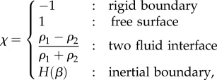 |
3.9b |
where
| 3.9c |
and the non-dimensional parameter β = ρh/σ, where σ is the mass per unit area of the boundary and E1(x) is an exponential integral. The last two examples yield the rigid surface and free surface values when the appropriate limits are taken.
We define the ‘stand-off’ parameter γ by
| 3.10 |
where h is the initial distance of the bubble centroid from the half-space boundary and Rm is the maximum bubble radius. Further scaling based on the maximum bubble radius Rm, the initial pressure difference  leads to dimensionless pressure P and time scale T,
| 3.11 |
The source strength m(t) is given by
| 3.12 |
whereas the integrated form of the dimensionless Rayleigh equation for the collapse of a spherical bubble in an infinite fluid yields
| 3.13 |
From equation (3.13), the collapse time, TR, for the Rayleigh spherical bubble may be calculated:
| 3.14 |
where B(x, y) is the beta function [13].
For large values of γ (typically 1.5–2.0 is adequate), the cavitation bubble will remain spherical for most of the first oscillation, thus we can exploit (3.13) together with the approach used in (3.14) to obtain a relationship between the Kelvin impulse and dimensionless parameters for the first oscillation.
In earlier studies [5,14,15], an estimate for the Kelvin impulse after both the growth and collapse phase (i.e. TC = 2TR) is given by
| 3.15 |
As stated by Benjamin & Ellis [2], the Kelvin impulse needs to be conserved by the generation of a circulation through and around the bubble, leaving the remnant toroidal bubble complex with circulation and vortex-structure flow system. However, immediately preceding the development of a liquid jet to provide the circulation, an accelerating motion of the bubble normally occurs in the direction of the Kelvin impulse, giving a useful prediction for the direction of jet formation and vortex circulation. Thus, for many examples
 |
3.16 |
In obtaining an enhanced physical understanding of bubble behaviour in a more complex domain, it is of value to introduce factors that either enhance or mitigate against the repulsion or attraction of bubbles towards boundaries. For example, an oscillating bubble is attracted towards a rigid boundary, repelled from a free surface.
One of the easiest additional factors to add to the force term Fx(t) is a buoyancy term ρgV(t), where V(t) is the time-dependent volume of the bubble, which for a spherical bubble is (4/3)πR3. Thus, on combining together (3.9a–c) and (3.15), we obtain
| 3.17 |
Through exploiting a change of variable, as used in obtaining the Rayleigh time TR (3.14) [5], we obtain, after scaling
 |
3.18 |
where the buoyancy parameter is given by
 |
3.19 |
While these relationships do have limitations in that the bubble cannot be too close to the boundary (γ > 1.5–2.0), and it will not remain spherical in the very final stages of collapse, they, nevertheless, do provide remarkable predictions of likely bubble behaviour in a range of experiments conducted worldwide in geometries that may be approximated by a semi-infinite flow domain.
The special cases we consider are buoyant bubbles near (i) a rigid boundary, (ii) a free surface, (iii) a two-fluid interface, (iv) a membrane-like boundary, and (v) behaviour in an axisymmetric stagnation point flow.
3.3. Case studies
3.3.1. Rigid boundary
In the case of a buoyant cavitation bubble above a rigid boundary (i.e. gravity downwards), we obtain
| 3.20a |
For a near-zero Kelvin impulse at the end of the first pulsation
 |
3.20b |
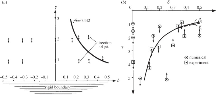
In figure 3a, the γ–δ parameter space shows computations studies at different (γ, δ) values for a rigid boundary. Above the γδ = 0.442 curve, the bubbles are repelled away from the rigid boundary, leading to a high-speed liquid jet directed away from the boundary. Below γδ = 0.442, the cavitation bubble is attracted towards the rigid boundary, directing a high-speed jet in this direction. Thus, the rectangular hyperbola in (γ, δ) parameter space given by γδ = 0.442 appears to be a reasonably accurate prediction of bubble behaviour in these situations.
Figure 3.
The γ–δ parameter space for buoyant vapour bubbles. The curve obtained from the null-Kelvin impulse is indicated, together with a selection of parameter values from numerical experiments and experiments in (b). The arrowheads indicate the direction of bubble migration and jet formation for a bubble near (a) a rigid boundary and (b) a free surface.
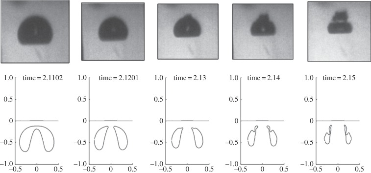
Figure 4 shows a comparison between an experiment near a rigid boundary [16] and computations based on the code developed by Curtiss et al. [17] for a two-fluid interface with ρ* = 100 for this calculation.
Figure 4.
Comparison between experimental and numerical results for h = 1.1 in the vicinity of a rigid boundary.
3.3.2. Free surface
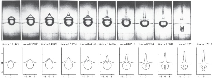
In this case with the cavitation bubble beneath the free surface, the same proportionality as the rigid boundary is obtained, leading again to γδ = 0.442 for the neutral curve. Figure 3b shows the neutral curve γδ = 0.442 (labelled β0 here) computational results for selected (γ, δ) values and, additionally, experimental results [14]. Again in figure 5, good agreement is obtained between experimental, computational and global theory based on the Kelvin impulse, with ρ* = 0 in this computation.
Figure 5.
Comparison between an experiment by Blake & Gibson [18] of behaviour near a free surface at γ = 0.56 and the numerical simulation with ρ* = 0, continuing into toroidal phase.
3.3.3. Two-fluid interface
For a two-fluid interface, the Atwood ratio At is introduced as follows:
| 3.21 |
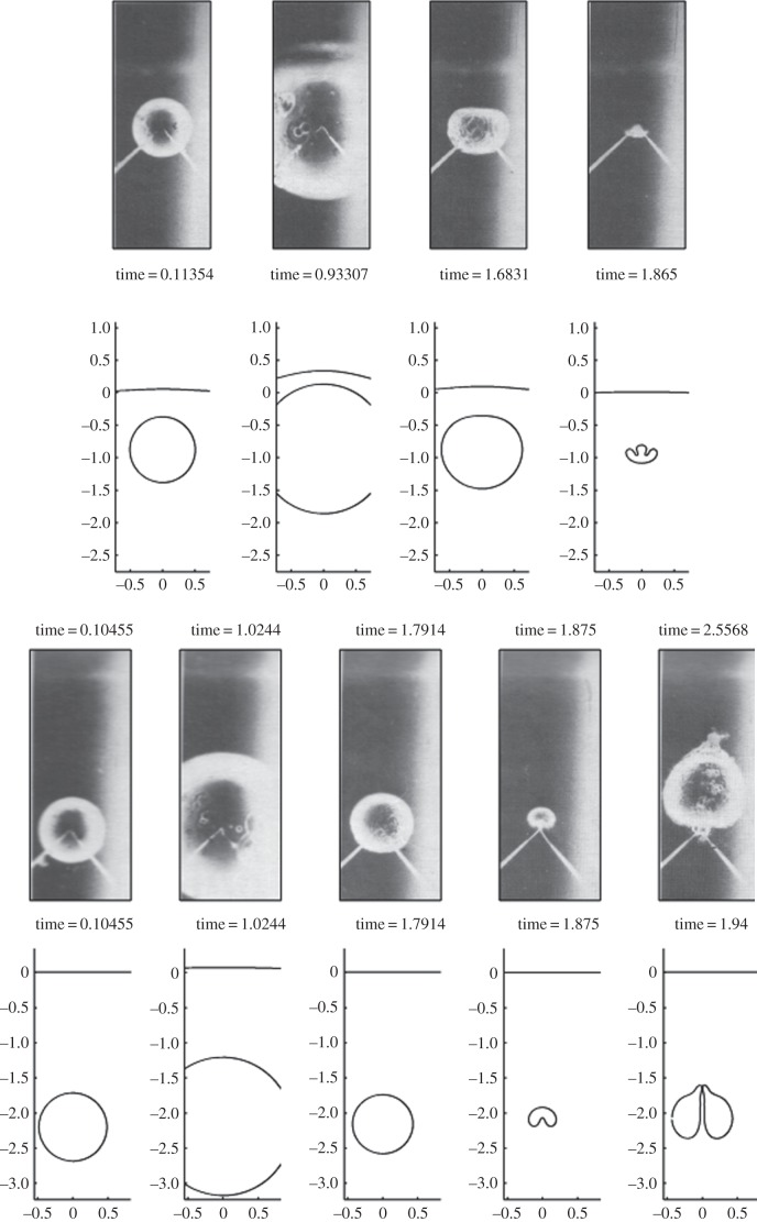
where ρ* is the density ratio across an interface. Chahine & Bovis [19] conducted experiments at a white spirit/water interface yielding a density ratio of ρ* = 0.76. The stand-off parameters used were γ = 0.87 and γ = 2.2. Substituting these data into (3.18) indicates Ix(TC) is less than zero for γ = 0.87 suggesting repulsion from the white spirit/water interface, whereas for γ = 2.2, Ix(TC) is positive indicating attraction towards the interface. Computational studies reported in Curtiss [20] confirm the behaviour recorded in the experiments by Chahine & Bovis [19] and are shown in figure 6.
Figure 6.
Comparisons between experiments near a water/white spirit interface ρ* = 0.76, by Chahine & Bovis [19], used with permission, and the numerical code for γ = 0.87 (top) and γ = 2.2 (bottom). The final frames in both cases are where the simulation ends due to either non-axial jet impact (top) or jet disconnection (bottom), and resultantly the times of the final frames for γ = 2.2 are not the same time. Other parameters are estimated as α = 100, Cab = 0.001.
3.3.4. Inertial and membrane boundary
For the case of the inertial boundary where β = ρh/σ, Ix(TC) is proportional to H(β), a function defined in (3.9c) (see also Blake & Cerone [8] for the graphical illustration of H(β)). Points of interest are when β → ∞ when H(β) → 1, corresponding to the rigid boundary; and when β → 0, corresponding to the potential free surface when H(β) → −1, as expected. The case H(β0), the null Kelvin impulse, yields β0 = 0.7798, corresponding to the ‘neutral collapse’ state when no migration takes place. However, the cavitation bubble may develop inward jets around the equator (‘inward equatorial jet’ of (3.17)), splitting the bubble in two as can occur near membrane boundaries [14,21] or in a stagnation point flow [11,15,22] (see also figures 8 and 10). A comparison with the studies by A. Shima and Y. Tomita (1987, personal communications), reported in [5], can be made if we define the thickness of the rubber sheet (inertial boundary) by tR, while ρR is its density, then the mass per unit area σ = ρRtR. On rearranging, we obtain
| 3.22 |
Figure 8.
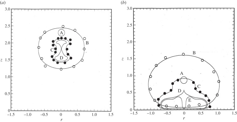
Theoretical bubble profiles for the parameter combination: (a) α = 0.124 and γ = 2.31 at times t = 0.0 (A), 1.76 (B), 1.96 (C) and 1.97 (D) with comparisons to experimental results at time t = 1.59 (open circles) and 1.75 (filled circles), and (b) α = 0.167 and γ = 0.87 at times t = 0.0 (A), 1.05 (B), 1.98 (C), 2.08 (D) and 2.09 (E) with comparisons to experimental results at time t = 1.05 (open circles) and 1.86 (filled circles).
Figure 10.
Bubble shapes for buoyant vapour bubbles in axisymmetric stagnation-point flow near a boundary for indicated values of α, γ and δ used in figure 8.
The r.h.s. of (3.22) is seen to be approximately constant for the experimental conditions considered by A. Shima and Y. Tomita (1987, personal communications) as seen in table 1.
Table 1.
Parameters for rubber sheet where tR is the sheet thickness (see (3.22) for further details).
| tR(mm) | h/Rm | (h/Rm)/tR |
|---|---|---|
| 3.0 | 1.31 | 0.44 |
| 4.0 | 1.66 | 0.42 |
| 5.0 | 2.11 | 0.42 |
The comparison is interesting but we also need to qualify this apparent similarity with the limitations on the theory being linear and with the right-hand ratio being dimensional.
3.3.5. Stagnation point flow
Returning to one of the quotations from Benjamin & Ellis [2] concerning ‘cavitation damage induced by flow is often most severe in the neighbourhood of stagnation points…’, we investigate this behaviour through the studies of Starrett [22] and Ellis & Starrett [23] for bubble behaviour in an axisymmetric stagnation point flow, depicted in figure 2c. To set the scene, consider the schematic illustration of a cavitating flow highlighting the flow around the reattachment point of the boundary layer showing a stagnation point flow (figure 7).
Figure 7.
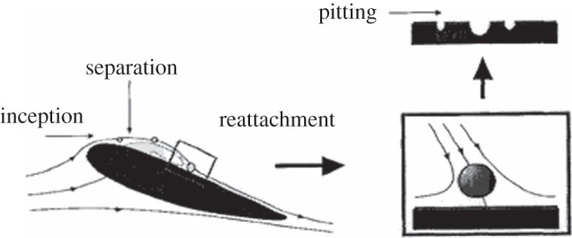
Schematic of a cavitation bubble moving over a hydrofoil showing the stagnation point flow at reattachment.
The theoretical and computational studies of cavitation bubbles near either a forward or rearward axisymmetric stagnation point flow are drawn from the studies of Blake et al. [15], Blake & Robinson [11] and Blake [5].
The theory involves the addition of an axisymmetric stagnation point flow given by
| 3.23 |
where the sign of C0 determines whether it is a forward or rearward stagnation point flow. The dimensionless parameter used to describe the flow is given by
 |
3.24 |
An incident stagnation point flow introduces two new facets to consider: first, the cavitation bubble is immersed in an ambient flow translating the bubble either toward (forward) or away (rearward) from the stagnation point compared with the essentially static initial state of previous examples, and second, a pressure gradient generated by the flow which is directed towards the stagnation point yielding a ‘buoyancy-type’ force on the bubble directed away from the boundary. Thus, this added feature adds two new behavioural features:
(i) forward stagnation point—flow towards the boundary but a pressure driving the bubble away and
(ii) rearward stagnation point—flow away from the boundary and pressure gradient also driving the bubble away.
However, this needs to be coupled with a Bjerknes attraction for the pulsating bubble towards the rigid boundary. Similar analyses to previously, but by incorporating the dynamic pressure field yield, for a fixed point source model of the cavitation bubble, the following algebraic equation for the zero Kelvin impulse state:
| 3.25 |
where the dimensionless stagnation point flow parameter is given in (3.24). A sample of the many observations from Starrett's thesis shown is figure 8 for the values of α = 0.167 and γ = 0.87 in figure 8a and α = 0.124 and γ = 2.31 in figure 8b.
The values of the two parameters γ and α for the two experiments from Starrett [22] and Ellis & Starrett [23] are provided in table 2. In figure 9, the fixed sphere case given by the critical value in (3.25) is shown with a continuous line, whereas a more sophisticated translating spherical cavitation bubble yields the dashed line, but which requires the solution of an ordinary differential equation, rather than the algebraic expression of (3.25). For the studies in this paper with α < 0.15, there is little difference between the two approximations, the difference only occurring for strong stagnation point flow of α > 0.3.
Table 2.
Parameters and commentary on the experiments.
| γ | α | γ3/2α | commentary |
|---|---|---|---|
| 0.87 | 0.09 | 0.073 | attracted to boundary, high-speed jet directed towards boundary |
| 2.31 | 0.126 | 0.44 | null Kelvin impulse bubble splitting at ‘equator’ |
Figure 9.
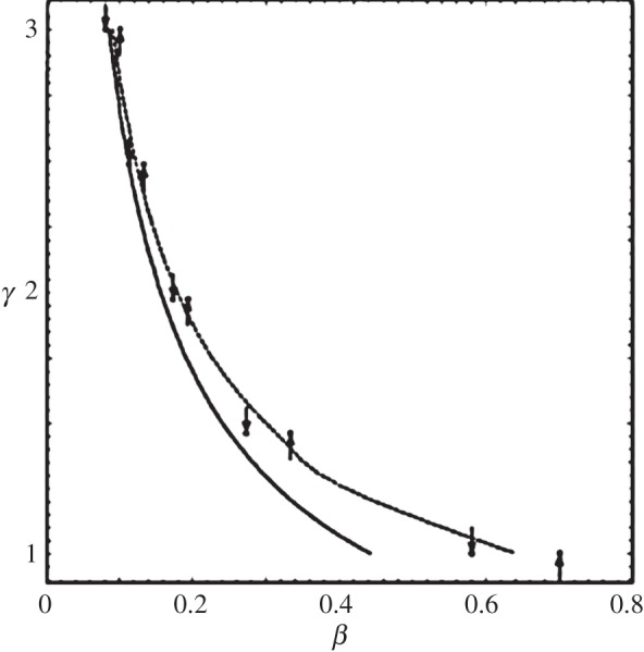
The null impulse curve axisymmetric buoyant vapour bubbles in a stagnation point flow, (solid line) fixed spherical bubble, (dashed line) translating spherical bubble.
Experimentally and computationally, this example yields a range of fascinating behaviours that reveals insights into more practical hydraulic cavitation studies around hydrofoils. Computational studies for the two experiments are illustrated in figure 10. In figure 10a, a very high-speed liquid jet is directed towards the boundary. The earlier stages of the bubble shape are remarkably similar to the experimental studies shown in figure 10. In figure 10b, the calculation is almost exactly at the null Kelvin impulse state, showing the bubble splitting phenomena. In figure 10c, the calculation has been extended beyond splitting to show the extremely high-speed needle-like jets, driven by the very high pressure generated on the axis by the impact of the equatorial jet on the axis of symmetry.
4. Ultrasonic bubbles near a wall
Acoustically driven cavitation is widely used for cleaning electrical and medical microdevices [24–26]. Bubble collapse near a solid surface results in high-speed liquid jets impinging on the solid, responsible for ultrasonic cleaning. In sonochemistry, acoustic cavitation is used to promote mixing and reactions [27,28].
Bubbles tend to maintain sphericity owing to surface tension. When subjected to ultrasound, its pressure gradient generates non-spherical bubble motion. If the wave is strong enough, a high-speed liquid jet forms towards the end of collapse. Axisymmetric jetting for acoustic bubbles in an infinite liquid was studied by Calvisi et al. [29], Wang & Blake [30,31], and near a boundary subjected to ultrasound propagating in the direction perpendicular to the boundary by Klaseboer & Khoo [32,33], Fong et al. [34,35], Calvisi et al. [29,36] and Curtiss et al. [17]. Wang & Manmi [37] implemented the three-dimensional boundary integral method (BIM) model for microbubble dynamics subjected to ultrasound propagated parallel to the boundary (figure 11).
Figure 11.
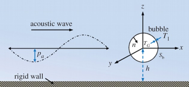
The configuration and coordinate system for a microbubble near a rigid wall subject to ultrasound propagating parallel to the wall. (Online version in colour.)
4.1. Physical and mathematical model
Consider the dynamics of a microbubble near an infinite rigid plane wall subject to ultrasound, as shown in figure 11. A Cartesian coordinate system is adopted with the origin at the centre of the initial spherical bubble, the z-axis perpendicular to the wall and the x-axis along the wave direction. The far-field pressure p∞ is thus modified to include a sinusoidal term
| 4.1 |
where p0 is the hydrostatic pressure, x is the coordinate along the propagation direction of the wave, t is time and pa, k and ω are the pressure amplitude, wavenumber and angular frequency, respectively, of the acoustic wave.
We assume that the pressure pb within the microbubble consists of the vapour pressure pv and non-condensing gas pressure pg:
| 4.2 |
where pg,0 is the initial gas pressure of the bubble, V0 is the initial bubble volume and λ is the ratio of specific heats of the gas. We set λ = 1.67 for the simulations presented here.
We assume that the fluid surrounding the bubble is incompressible and the flow is irrotational. The fluid velocity v thus has a potential φ,  which satisfies Laplace's equation,
  Using Green's second identity the potential φ may be represented as a surface integral over the bubble surface S as follows:
| 4.3 |
where r is the field point and q is the source point, c(r) is the solid angle and n is the unit outward normal of the bubble surface S directed from liquid to gas.
To satisfy the impermeable boundary condition on the wall, the Green function is given as follows:
| 4.4 |
where q′ is the image of q reflected in the wall.
We choose the reference length R0 (initial radius of the bubble) and the reference pressure Δp = p0 − pv. The dimensionless kinematic and dynamic boundary conditions on the bubble surface are given as follows:
| 4.5a |
and
 |
4.5b |
where the dimensionless variables are denoted with the subscript ‘*’, κ∗ is the local mean curvature, Reynolds number Re and Weber number We are defined by We = ΔpR0/σ.
4.2. Numerical model
The numerical model is based on the boundary integral method. At each time step, we have a known bubble surface and potential distribution φ on the bubble surface. With this information, we can calculate the tangential velocity on the bubble surface. The normal velocity on the bubble surface is obtained after solving the boundary integral equation (4.3). The bubble shape and the potential distribution on it can be further updated by performing the Lagrangian time integration to (4.15a,b), respectively, using the fourth-order Runge–Kutta scheme (RK4). The details of the numerical model using the BIM for the problem can be found in Wang [38,39] and Wang & Manmi [37]. The surface tension effect plays an important role in the dynamics of microbubbles. We thus need to calculate the mean curvature κ of the bubble surface associated with the surface tension effects. The bubble surface and potential distribution were interpolated using a polynomial scheme coupled with the moving least-square method for calculating the surface curvature and tangential velocity on the surface. The detailed model is found in [38–40].
4.3. Computations and analyses
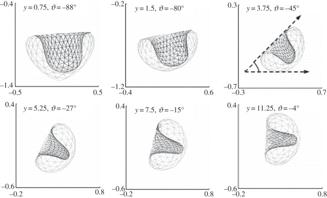
Figure 12 shows the bubble and jet shapes when the jet touches the far side of the bubble subjected to ultrasound travelling parallel to the rigid boundary at various stand-off distances in the range of  The parameters used are R0 = 4.5 µm, pa* = 1.6, f = 300 kHz, λ = 1.667, σ = 0.073 N m−1, p0 = 101.3 kPa, pv = 0.023p0 and ρ = 999 kg m−3. The jet is approximately directed towards the wall at γ = 0.75 (θ ≈ −88°), rotates anticlockwise to the direction of the ultrasound with increasing γ as the bubble initiated further away from the wall, and is approximately along the direction of the ultrasound (θ ≈ 4°) at γ = 11.25. Note that as the jet is slightly asymmetric, its direction θ is estimated from the direction of its baseline, which is assumed to be perpendicular to the jet. The jet width reduces with the stand-off distance γ.
Figure 12.
The jet direction at the end of collapse at various stand-off distances in the range of  The parameters used are R0 = 4.5 µm, pa* = 1.6, f = 300 kHz, λ = 1.667, σ = 0.073 N m−1, p0 = 101.3 kPa, pv = 0.023p0 and ρ = 999 kg m−3.
Figure 13 compares the direction θK of the Kelvin impulse with the direction θ of the bubble jet and the migration direction θc = tan−1(zc/xc) of the bubble centroid at the end of collapse. They are approximately equal for the cases considered. The Kelvin impulse is thus in the directions of the bubble jet and bubble migration for acoustic bubble dynamics. Figure 13 also shows that the magnitude IK* of the Kelvin impulse reduces with the stand-off distance of the bubble from the wall.
Figure 13.
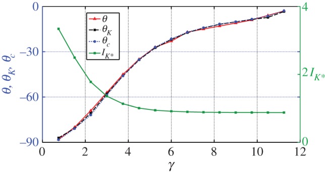
The direction θ of the bubble jet, the direction θc of migration of the bubble centroid, the direction θK and the amplitude IK* of the Kelvin impulse versus the stand-off distance γ for the cases shown in figure 12. (Online version in colour.)
The maximum volume, the lifetime and the Kelvin impulse of the bubble all increase with the amplitude of ultrasound. The jet direction does not change significantly with the amplitude of ultrasound. This is because the Bjerknes force owing to ultrasound and the second Bjerknes force owing to the rigid boundary increase with the amplitude of ultrasound in a similar way. The jet direction θ is approximately the same as the direction θK of the Kelvin impulse for all the cases considered.
5. A paradigm collapse model and the Longuet-Higgins jet
Another important feature that may influence the overall collapse characteristics of a cavity is the presence of some initial translational motion relative to the local fluid, as may occur if a pressure gradient exists. In this section, we calculate the collapse motion of an initially spherical cavity translating in an infinite fluid with initial velocity  relative to the general fluid motion.
As shown earlier that the Kelvin impulse is conserved in an infinite fluid, we might expect, as pointed out by Benjamin & Ellis [2], that the translational velocity of a cavity will increase rapidly as its volume decreases. The dimensionless translational velocity  for a spherical bubble of radius R(t) is given by
| 5.1 |
where U = U0/(Δp/ρ)1/2. The corresponding initial potential for a translating sphere, as defined by a dipole potential, yields the familiar quantity
| 5.2 |
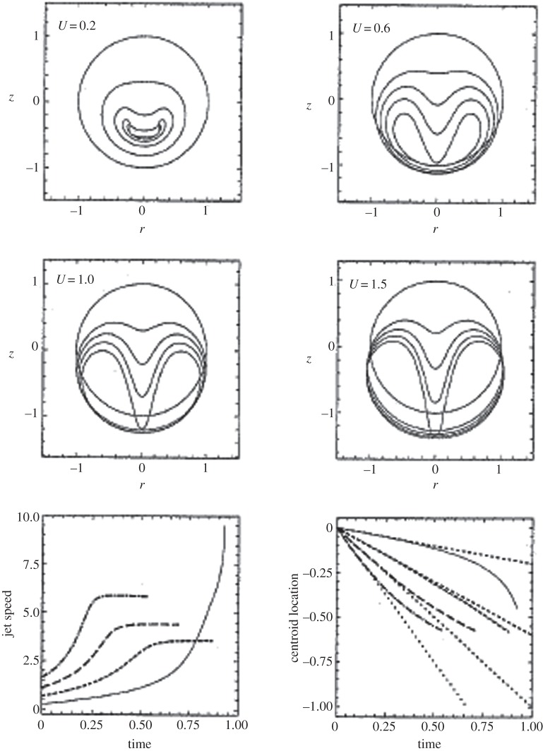
Examples of the evolution of the cavity shape are given in figure 14 for various values of U in the range 0.2–1.5. In all cases, a high-speed liquid forms in the region of higher fluid pressure which penetrates the bubble from the trailing edge. This trailing edge instability is due to the dipole, with this motion occurring more rapidly as U is increased. Indeed, for U = 1.5, the axial jet traverses the cavity before time t = 0.55 when compared with the Rayleigh collapse time t ≈ 0.915 with only a small reduction in the associated cavity volume.
Figure 14.
Shape profiles, jet speeds and centroid motions for an initially translating sphere in an infinite fluid with dimensionless speeds U = 0.2 (solid line), U = 0.6 (dotted line), U = 1.0 (dashed line) and U = 1.5 (dashed-dotted line).
Valuable information can be gained by considering the jet velocity and centroid motions as presented in the last two frames of figure 14. Of particular interest are the jet velocities obtained for the larger values of the translational velocity. Here, the maximum jet velocity occurs partway through the collapse phase just after jet formation, before assuming an almost constant value. This behaviour is found for virtually all the calculations reported in this study once the angle between the tangent to the jet profile becomes narrower than approximately 100°. This is reminiscent of the constant jet velocities found in the free surface ‘spike’ by Blake & Gibson [18] and later analysed by Longuet-Higgins [41] in greater detail. This suggests that a significant component of the Kelvin impulse is now contained in the liquid jet. Further insights may be obtained by plotting the centroid of the cavity and comparing this against the initial constant velocity movement of the bubble. The bolder lines are the calculated centroid positions, whereas the light dotted line corresponds to the constant velocity motion. For small U (less than 0.6), the centroid continues to move at near the initially imposed centroid velocity. However, at larger values of U the centroid velocity clearly decelerates, supporting the idea that the fluid momentum has been transferred to the high-speed liquid jet. Ultimately, we would expect this jet to penetrate the leading surface of the cavity evolving its surface into a toroidal form, with the fluid momentum being transferred into a ring vortex with a circulation compatible with the original Kelvin impulse.
Often, our intuitive ideas are based on the response we would expect for spherical bubbles in a prescribed flow field. As has been seen here, we would intuitively expect cavities to accelerate as the collapse, which indeed occurs for smaller translational velocities (e.g. U = 0.2), in part following the finite-time singularity described in §3. However, for larger initial velocities, a cavity undergoes rapid distortion and as a consequence decelerates.
6. Conclusion
The principal focus of this paper has been the derivation and application of the Kelvin impulse to cavitation bubbles in both infinite and semi-infinite liquids. The numerical value and vector direction of the Kelvin impulse in the final stage of collapse of a cavitation bubble provide information on the direction of translation and jet formation. This is of value in determining likely mechanisms for cavitation induced particle or cellular removal on nearby surfaces (e.g. epithelial cells, lesions, cancerous cells, particulate debris on electronic wafer boards).
The semi-infinite domain is developed for application to many experimental models in which a cavitation bubble is generated by either a spark discharge or laser near to a (typically) flat boundary, such as a rigid boundary or potential free surface. An approximate model for the spherical bubble typically exploits the Rayleigh equation of motion to enable a parameter space of dimensionless variables to be developed that can provide valuable and accurate predictions on likely bubble behaviour. However, the Kelvin impulse was initially developed to ensure computational accuracy by calculating global bubble behaviour to see if the calculations are consistent. A recent example is a study by Wang & Manmi [37] which uses the Kelvin impulse to predict the direction of motion of the high-speed liquid jet for a bubble subjected to high intensity ultrasound parallel to a flat wall.
A number of ‘paradigm bubble’ models are available to consider aspects of cavitation bubble collapse. In this paper, consideration is given to the collapse characteristics of an initially translating spherical bubble in an infinite fluid when it has a constant Kelvin impulse. For initial dimensionless translational velocities of above 0.2, a Longuet-Higgins liquid jet, where the region is modelled as a Dirichlet hyperboloid, yields a constant tip-velocity formed when the tangent to the now convex part of the bubble surface subtends an angle less than the critical value of 100°.
Future studies of the paradigm bubble model will consider conservation of the Kelvin impulse when the bubble becomes multiply-connected with the generation of a vortex-ring bubble.
Acknowledgements
This research was supported over the period 1980–2006 by the ARGC, ARC, DSTO and CSIRO in Australia and the EPSRC, DERA and QinetiQ in the UK. We thank Chantal Jackson for her developments of figure 1 and Dr Mark Esson for extensive assistance with the production of the paper.
Competing interests
We declare we have no competing interests.
Funding
We received no funding for this study.
References
- 1.Batchelor GK. 1967. An introduction to fluid dynamics. Cambridge, UK: Cambridge University Press. [Google Scholar]
- 2.Benjamin TB, Ellis AT. 1966. The collapse of cavitation bubbles and the pressures thereby produced against solid boundaries. Phil. Trans. R. Soc. Lond. A 260, 221–240. ( 10.1098/rsta.1966.0046) [DOI] [Google Scholar]
- 3.Saffman PG. 1967. Self propulsion of a deformable body in a perfect fluid. J. Fluid Mech. 28, 385–389. ( 10.1017/S0022112067002149) [DOI] [Google Scholar]
- 4.Wu TY. 1976. The momentum theorem for a deformable body in a perfect fluid. Schiffstechnik 23, 229–232. [Google Scholar]
- 5.Blake JR. 1988. The Kelvin impulse: application to cavitation bubble dynamics. J. Aust. Math. Soc. 30, 127–146. ( 10.1017/S0334270000006111) [DOI] [Google Scholar]
- 6.Lamb H. 1932. Hydrodynamics. Cambridge, UK: Cambridge University Press. [Google Scholar]
- 7.Landau LD, Lifshitz EM. 1975. Fluid mechanics: Landau and Lifshitz: course of theoretical physics. Oxford, UK: Butterworth-Heinemann. [Google Scholar]
- 8.Blake JR, Cerone P. 1982. A note on the impulse due to a vapour bubble near a boundary. J. Aust. Math. Soc. 23, 383–393. ( 10.1017/S0334270000000321) [DOI] [Google Scholar]
- 9.Rayleigh L. 1917. On the pressure developed in liquid during the collapse of a spherical void. Phil. Mag. 34, 94–98. ( 10.1080/14786440808635681) [DOI] [Google Scholar]
- 10.Plesset MS, Chapman RB. 1971. Collapse of an initially spherical vapour cavity in neighbourhood of a solid boundary. J. Fluid Mech. 47, 283–290. ( 10.1017/S0022112071001058) [DOI] [Google Scholar]
- 11.Robinson PB, Blake JR. 1994. Dynamics of cavitation bubble interactions. In Fluid mechanics and its applications, vol. 23 (eds Blake JR, Boulton-Stone JM, Thomas NH), pp. 55–64. Dordrecht, The Netherlands: Kluwer. [Google Scholar]
- 12.Leppinen DM, Wang QX, Blake JR. 2013. Pulsating bubbles near boundaries. Bubble Dyn. Shockwaves 8, 33–65. ( 10.1007/978-3-642-34297-4_2) [DOI] [Google Scholar]
- 13.Abramowitz M, Stegun IA. 1964. Handbook of mathematical functions with formulas, graphs and mathematical tables. New York, NY: Dover. [Google Scholar]
- 14.Blake JR, Gibson DC. 1987. Cavitation bubbles near boundaries. Annu. Rev. Fluid Mech. 19, 99–123. ( 10.1146/annurev.fl.19.010187.000531) [DOI] [Google Scholar]
- 15.Blake JR, Taib BB, Doherty G. 1986. Transient cavities near boundaries. Part 1. Rigid boundaries . J. Fluid Mech. 170, 479–497. ( 10.1017/S0022112086000988) [DOI] [Google Scholar]
- 16.Brujan EA, Keen G, Vogel A, Blake JR. 2002. The final stages of collapse of a cavitation bubble close to a rigid boundary. Phys. Fluids 14, 85–92. ( 10.1063/1.1421102) [DOI] [Google Scholar]
- 17.Curtiss GA, Leppinen DM, Wang QX, Blake JR. 2013. Ultrasonic cavitation near a tissue layer. J. Fluid Mech. 730, 245–272. ( 10.1017/jfm.2013.341) [DOI] [Google Scholar]
- 18.Blake JR, Gibson DC. 1981. Growth and collapse of a vapour cavity near a free surface. J. Fluid Mech. 111, 123–140. ( 10.1017/S0022112081002322) [DOI] [Google Scholar]
- 19.Chahine GL, Bovis AG. 1980. Oscillation and collapse of a cavitation bubble in the vicinity of a two liquid interface. Springer Ser. Electrophys. 4, 23–29. [Google Scholar]
- 20.Curtiss GA. 2009. Non-linear, non-spherical bubble dynamics near a two fluid interface. Birmingham, UK: The University of Birmingham. [Google Scholar]
- 21.Shima A, Tomita Y, Gibson DC, Blake JR. 1989. The growth and collapse of cavitation bubbles near composite surfaces. J. Fluid Mech. 203, 199–214. ( 10.1017/S0022112089001436) [DOI] [Google Scholar]
- 22.Starrett JE. 1982. Bubble dynamics in stagnation flow. San Diego, CA: University of California. [Google Scholar]
- 23.Ellis AT, Starrett JE. 1983. A study of cavitation bubble dynamics and the resultant pressures on adjacent solid boundaries. In Proc. 2nd Int. Conf. on Cavitation, Edinburgh, UK, September 1983, paper C190/83.
- 24.Song WD, Hong MH, Lukyanchuk B, Chong TC. 2004. Laser-induced cavitation bubbles for cleaning of solid surfaces. J. Appl. Phys. 95, 2952–2956. ( 10.1063/1.1650531) [DOI] [Google Scholar]
- 25.Ohl CD, Arora M, Ikink R, de Jong N, Versluis M, Delius M, Lohse D. 2006. Sonoporation from jetting cavitation bubbles. Biophys. J. 91, 4285–4295. ( 10.1529/biophysj.105.075366) [DOI] [PMC free article] [PubMed] [Google Scholar]
- 26.Lauterborn W, Kurz T. 2010. Physics of bubble oscillations. Rep. Prog. Phys. 73, 106501 ( 10.1088/0034-4885/73/10/106501) [DOI] [Google Scholar]
- 27.Blake JR, Keen GS, Tong RP, Wilson M. 1999. Acoustic cavitation: the fluid dynamics of non-spherical bubbles. Phil. Trans. R. Soc. A 357, 251–267. ( 10.1098/rsta.1999.0326) [DOI] [Google Scholar]
- 28.Fernandez Rivas D, Stricker L, Zijlstra AG, Gardeniers HJGE, Lohse D, Prosperetti A. 2013. Ultrasound artificially nucleated bubbles and their sonochemical radical production. Ultrason. Sonochem. 20, 510–524. ( 10.1016/j.ultsonch.2012.07.024) [DOI] [PubMed] [Google Scholar]
- 29.Calvisi ML, Lindau O, Blake JR, Szeri AJ. 2007. Shape stability and violent collapse of microbubbles in acoustic travelling waves. Phys. Fluids 19, 047101 ( 10.1063/1.2716633) [DOI] [Google Scholar]
- 30.Wang QX, Blake JR. 2010. Non-spherical bubble dynamics in a compressible liquid. Part 1. Travelling acoustic waves. J. Fluid Mech. 659, 191–224. ( 10.1017/S0022112010002430) [DOI] [Google Scholar]
- 31.Wang QX, Blake JR. 2011. Non-spherical bubble dynamics in a compressible liquid. Part 2. Acoustic standing wave. J. Fluid Mech. 679, 559–581. ( 10.1017/jfm.2011.149) [DOI] [Google Scholar]
- 32.Klaseboer E, Khoo BC. 2004. Boundary integral equations as applied to an oscillating bubble near a fluid–fluid interface. Comput. Mech. 33, 129–138. ( 10.1007/s00466-003-0508-2) [DOI] [Google Scholar]
- 33.Klaseboer E, Khoo BC. 2004. An oscillating bubble near an elastic material. J. Appl. Phys. 96, 5808–5818. ( 10.1063/1.1803925) [DOI] [Google Scholar]
- 34.Fong SW, Klaseboer E, Turnagan CK, Khoo BC, Hung KC. 2006. Numerical analysis of a gas bubble near biomaterials in an ultrasound field. Ultrasound Med. Biol. 32, 925–942. ( 10.1016/j.ultrasmedbio.2006.03.005) [DOI] [PubMed] [Google Scholar]
- 35.Fong SW, Klaseboer E, Khoo BC. 2008. Interaction of microbubbles with high intensity pulsed ultrasound. J. Acoust. Soc. Am. 123, 1784–1793. ( 10.1121/1.2836746) [DOI] [PubMed] [Google Scholar]
- 36.Calvisi ML, Iloreta JI, Szeri AJ. 2008. Dynamics of bubbles near a rigid surface subjected to a lithotripter shock wave. Part 2. Reflected shock intensifies non-spherical collapse. J. Fluid Mech. 616, 63–97. ( 10.1017/S0022112008003054) [DOI] [Google Scholar]
- 37.Wang QX, Manmi K. 2014. Three dimensional microbubble dynamics near a wall subject to high intensity ultrasound. Phys. Fluids 26, 032104 ( 10.1063/1.4866772) [DOI] [Google Scholar]
- 38.Wang QX. 1998. The evolution of a gas bubble near an inclined wall. Theor. Comput. Fluid Dyn. 12, 29–51. ( 10.1007/s001620050097) [DOI] [Google Scholar]
- 39.Wang QX. 2004. Numerical modelling of violent bubble motion. Phys. Fluids 16, 1610–1619. ( 10.1063/1.1704645) [DOI] [Google Scholar]
- 40.Wang QX. 2005. Unstructured MEL modelling of unsteady nonlinear ship waves. J. Comput. Phys. 210, 183–224. ( 10.1016/j.jcp.2005.04.015) [DOI] [Google Scholar]
- 41.Longuet-Higgins MS. 1983. Bubbles, breaking waves and hyperbolic jets at a free surface. J. Fluid Mech. 127, 103–121. ( 10.1017/S0022112083002645) [DOI] [Google Scholar]


