Abstract
Studies on the deformation behaviours of cellular entities, such as coated microbubbles and liposomes subject to a cavitation flow, become increasingly important for the advancement of ultrasonic imaging and drug delivery. Numerical simulations for bubble dynamics of ultrasound contrast agents based on the boundary integral method are presented in this work. The effects of the encapsulating shell are estimated by adapting Hoff's model used for thin-shell contrast agents. The viscosity effects are estimated by including the normal viscous stress in the boundary condition. In parallel, mechanical models of cell membranes and liposomes as well as state-of-the-art techniques for quantitative measurement of viscoelasticity for a single cell or coated microbubbles are reviewed. The future developments regarding modelling and measurement of the material properties of the cellular entities for cutting-edge biomedical applications are also discussed.
Keywords: ultrasonic cavitation, membrane mechanics, microbubble dynamics, single-cell mechanics, boundary integral method
1. Introduction
It becomes increasingly prevalent for cavitation to be applied to biomedicine including ultrasound contrast agents (UCAs), drug delivery [1], sonoporation [2] and cell separation (Patent US20120164113 A1). A better understanding of the complex interplay between a cavitational flow and a cell or cell-like membrane is of paramount importance to the fundamental optimization of these applications. An interdisciplinary approach combining cell mechanics with bubble dynamics can be highly desirable to elucidate the deformation behaviours of cellular entities subject to cavitation flow and to enhance drug delivery via coated microbubbles [3]. These developments will fundamentally advance our knowledge of targeted drug delivery and sonoporation. They will also have important applications in ultrasound diagnostics, such as analysing potential bio-effects of ultrasound-activated microbubbles on micro-vessels. Moreover, ultrasonic cavitation is one of the most effective cleaning agents. For example, it is used to clean and to disinfect surgical instruments in hospitals. Moreover, ultrasonic cavitation has been recently applied to harvest mesenchymal or stromal vascular cells from lysed blood vessels contained in ultrasonicated adipose tissue (Patent US8440440). Although the new technique has significantly maintained viability of the cells, the intricate cell–bubble interaction needs to be carefully examined for its further clinical applications.
Typical UCAs are micrometre-sized (typically between 0.5 and 10 µm in diameter) gas bubbles stabilized by biologically inert coatings such as lipid, protein and polymer [4]. A recent review introduces compressively state-of-the-art techniques to generate both coated and uncoated microbubbles and a theoretical model to describe the physics of the bubble formations [5]. That paper also reports several modern techniques to produce UCAs which are coated with phospholipid shell or surfactant membrane, and concludes that microfluidics is a promising approach to control precisely the sizes and coating properties of UCAs in their production. When UCAs are injected into the bloodstream, they can travel to all the blood vessels. Their high compressibility relative to blood/tissues leads to strong scattering of ultrasound waves, thereby enhancing blood–tissue contrast in the resulting image. UCAs are thus widely used in clinical diagnostic ultrasound to enhance contrast of cardiographic or radiologic features [6,7].
UCAs are rapidly evolving from the diagnostic modality into a therapeutic tool [1]. One important potential application is to use UCAs to deliver a drug/gene for ultrasound therapy, e.g. cancer treatment [8]. Upon arriving at a targeted site, the microbubbles are activated by ultrasound leading to violent collapse. This releases the drug/gene cargo and also causes cell membranes nearby to become temporarily leaky, a phenomenon known as sonoporation [9,10]. The mechanism aids the gene/drug to enter the target cells via diffusion and also convection if microjets arise [11–13].
Targeted drug delivery improves disease treatment efficacy and safety, as well as patient convenience and compliance. It is of particular interest for pharmaceutical agents that yield detrimental side effects. It has been generating worldwide interest in the communities of both scientists and clinical researchers [1]. Detailed experimental studies have revealed considerable evidence of the leaking of a transported drug from coated bubbles. It has been established by numerous groups that the localized cellular uptake of drugs/genes is significantly increased when microbubbles are present [1].
On the theoretical front, coated bubble dynamics is an extension of traditional bubble dynamics. Most studies on the topic were based on spherical bubble theory, the Rayleigh–Plesset (RP) equation incorporated with linear and nonlinear cellular membrane models [14], and the shape stability of a nearly spherical bubble [15]. However, non-spherical coated bubbles are frequently present in medical applications, such as: (i) the onset of breaking of the bubble coating in releasing drugs is directly linked to the loss of spherical symmetry [1] and (ii) the sonoproation is associated with a bubble interacting with a cell nearby [1]. Chen et al. [16] observed that coated ultrasound bubbles in micro-blood vessels of rat mesentery are often associated with non-spherical deformation and liquid jetting and the study shows there is a need to develop new theoretical models for describing non-spherical deformation of bubbles (figure 1).
Figure 1.
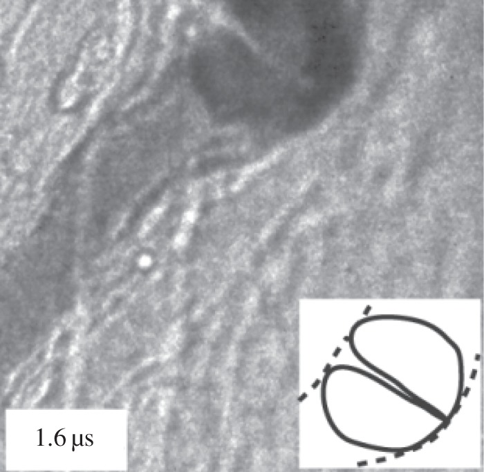
Vascular rupture involving a liquid jet. Amplitude of ultrasound = 4 MPa. Vessel diameter = 15 µm. Sketches of the bubble jet in solid lines and microvessel in dashed lines. Adapted from Chen et al. [16].
Lipid bilayer forming the major constituent of plasma membrane plays a crucial role in sustaining the integrity and functions of biological cells. Liposome is an artificial cellular entity (a few micrometres in diameter) where a liquid drop or gas is closed by a lipid bilayer membrane (about 10 nm in thickness) and is often used as a model cell in biomechanical studies. Liposome has long been used as drug delivery vehicle by encapsulating drugs within the bilayer membrane since it exhibits excellent biocompatibility such as longer lifespan in blood circulation, low toxicity and easily taken up by targeted tissue [17]. Recently, ultrasonic cavitation has been applied to trigger or induce drug release from liposome [18] (figure 2). The mechanical characterization of a single liposome attracts increasing interests in the scientific community, for instance, analysis of the deformation of lipid-coated microbubble or echogenic liposome for both drug delivery and sonoporation [19].
Figure 2.
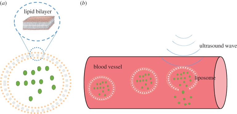
(a) Structure of liposome. (b) Ultrasonic cavitation induces drug release from liposome. (Online version in colour.)
Theoretical models integrating bubble dynamics with mechanics of cell membrane or coated membrane are desirable for design of the next generation of ultrasonic contrast agents and drug delivery systems. In §2, numerical simulations for the dynamics of the UCAs by using boundary integral method (BIM) are presented based on a simple model for the coating shell of microbubbles. We also review mechanical models of bubble coating and liposome in §3 and the state-of-the-art techniques for quantitative measurement of viscoelasticity of a single cell or coated microbubble are presented in §4.
2. Dynamics of coated microbubbles based on Hoff's model
2.1. Computational bubble dynamics
The BIM based on the potential flow theory is grid-free in the flow domain and has been widely used in bubble boundary interactions for axisymmetric cases [20–29] and for three-dimensional configurations [30–33]. Recently, Wang et al. [34–37] developed the BIM for bubble dynamics in a compressible liquid.
Bubble dynamics have been simulated using domain approaches, such as the high-order accurate shock- and interface-capturing scheme [38], orthogonal boundary-fitted grids for axisymmetric bubbles [39], the free-Lagrange method [40], the arbitrary Lagrangian Eulerian method [41] and front tracking method coupled with SIMPLE algorithm [42]. Direct simulation for multiple oscillations of acoustic bubbles is highly computationally demanding. It is a multi-scale problem when the compressible effects of the liquid are not negligible, since the wavelength is much larger than the bubble radius. It involves a large computational domain for describing the propagation of the acoustic wave, and a very long time interval. Hsiao & Chahine [43] recently modelled the bubble coating using a layer of a Newtonian viscous fluid, to study the mechanism of bubble break-up during non-spherical deformations resulting from the presence of a nearby rigid boundary. The effects of the shell thickness and the bubble standoff distance from the solid wall on the bubble break-up were studied parametrically.
2.2. Non-spherical coated microbubble dynamics
Consider the dynamics of UCAs near an infinite rigid plane wall subject to ultrasound, as shown in figure 3. We assume that the fluid surrounding the bubble is incompressible and the flow is irrotational. The fluid velocity v thus has a potential φ, v = ∇φ, which satisfies Laplace's equation, ∇2φ = 0. Using Green's second identity, the potential φ can be represented as a surface integral over the bubble surface S as follows:
| 2.1 |
where r is the field point and q is the source point, c(r) is the solid angle and n is the unit outward normal of the bubble surface S directed from liquid to gas. To satisfy the impermeable boundary condition on the wall, the Green function is given as follows:  where q' is the image of q reflected to the wall.
Figure 3.
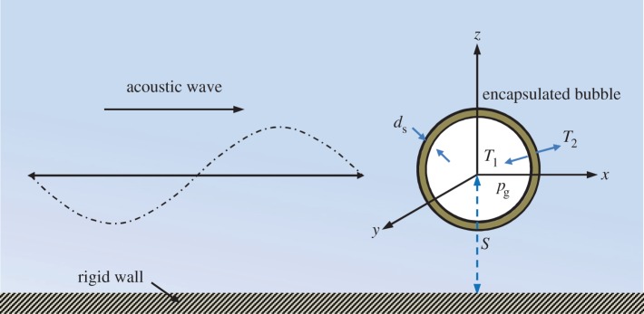
Schematic of an encapsulated microbubble subject to ultrasonic wave, travelling near a rigid wall. (Online version in colour.)
The kinematic boundary condition on the bubble surface is
| 2.2 |
The dynamic boundary condition on the bubble surface is
| 2.3 |
where ρ is the liquid density and σ is the surface tension coefficient. The first term pg in the right bracket is the gas pressure inside the UCA. Since we consider rapidly collapsing bubbles, pg is assumed to follow the adiabatic law  Here pg0 is the initial gas pressure inside the UCA, V and V0 are the instantaneous and initial bubble volumes, respectively. Here α is the ratio of specific heats of the interior gas. Unless otherwise noted, we set α = 1.67 (argon) for the simulations presented here. The second term
  is the far-field pressure,
  where p0 is the hydrostatic pressure, x is the coordinate along the direction of the wave, t is the time, and pa, k and ω are the pressure amplitude, wavenumber and angular frequency of the acoustic wave, respectively.
The third term is associated with the surface tension effect, where σ is the surface tension and Rc is the curvature radius of the bubble surface. The fourth term is the normal viscous stress. The fifth term is the radial pressure difference ΔT = T2 − T1 (figure 3), which is approximated by adapting Hoff's model [44] for the thin shell of spherical contrast agents, by replacing the bubble radius with the local curvature radius Rc as follows:
 |
2.4 |
where R0 is the initial bubble radius, ds is the shell thickness, and Gs and μs are the shear modulus and shear viscosity of the shell, respectively. The overdot denotes differentiation with respect to time.
We choose the reference length R0 and the reference pressure p0 to introduce the following dimensionless quantities denoted by an asterisk (*):
| 2.5 |
and
| 2.6 |
Following convention, the standoff distance is non-dimensionalized with respect to the maximum equivalent bubble radius:
| 2.7 |
where S is the distance between the wall and the bubble centre at inception (figure 3), and Rmax is the maximum radius a bubble initially in equilibrium would attain in an infinite ambient fluid subject to the imposed ultrasound.
We argue this simplified model can be used to approximate the essential effects of the coating for the following reasons. An encapsulated bubble is usually approximately spherical during most of its lifetime except for a short period during the end of collapse when the bubble becomes non-spherical. This model thus provides a good estimation for the influence of the shell on the bubble, the asymmetric flow and pressure fields prior to jet development. When liquid jetting starts, the large asymmetric momentum of the liquid flow and high pressure of the bubble gas are dominant effects; the elastic and viscous effects of the thin coating should be secondary effects.
2.3. Numerical results
To validate this model for the restricted case of spherical oscillation of a coated bubble, the results were compared to the modified RP equation used by Hoff [44] that accounts for the elastic and viscous effects of the shell. Using the present notation, this equation is given by
 |
2.8 |
Note that the term for the time derivative of the liquid pressure is neglected in the above equation, as we assume an incompressible liquid.
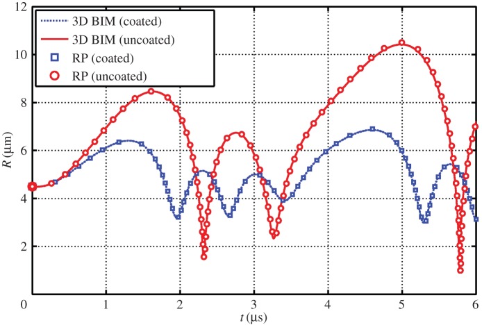
Figure 4 shows comparisons of the bubble radius time history for a coated and uncoated bubble as determined from the three-dimensional BIM model and modified RP. The BIM model agrees well with the modified RP for several cycles of oscillation for both coated and uncoated bubbles oscillating spherically subject to ultrasound.
Figure 4.
Comparisons of the bubble radius time history for a coated and uncoated bubble as determined from the three-dimensional BIM model and modified RP equation. The parameters used for the case are c = 1500 m s−1, α = 1.4, σ = 0.055 N m−1, ɛ = 1 + 2σ*, p0 = 100 kPa, ρ = 1000 kg m−3, R0 = 4.5 µm, pa* = 1.2, ω = 942 MHz, Gs = 10.0 MPa, ds = 15 nm, μs = 0 and μl = 3.5 Pa s. (Online version in colour.)
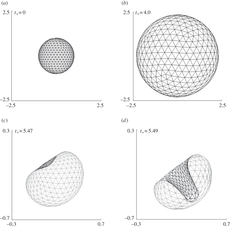
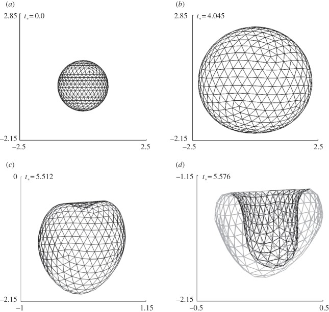
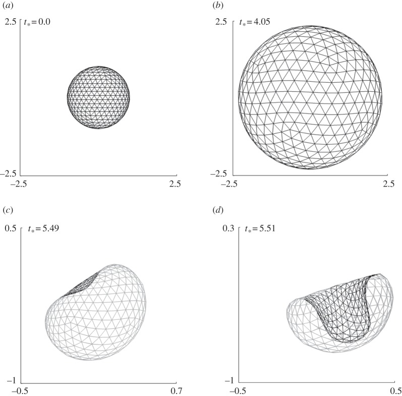
We study microbubble dynamics near a rigid wall subject to ultrasound propagating parallel to the wall. To study the effects of the standoff distance of the bubble from the wall, we consider three cases (figures 5–7) at γ = 1.0, 2.0 and 3.0, respectively, for pa* = 2.0, with the remaining parameters the same as in figure 4.
Figure 5.
Coated bubble dynamics near a wall subject to ultrasound propagating parallel to the wall for γ = 3.0, pa* = 2.0 with the remaining parameters the same as in figure 4. The bubble shapes are shown during the expansion phase (a,b) and collapse phase (b–d).
Figure 7.
Coated bubble dynamics near a wall subject to ultrasound propagating parallel to the wall for γ = 1.0, pa* = 2.0 with the remaining parameters the same as in figure 4. The bubble shapes are shown during the expansion phase (a,b) and collapse phase (b–d).
Figure 5 shows the typical bubble shapes for the case at γ = 3.0 at various stages during the expansion phase (figure 5a,b) and collapse phase (figure 5b–d). The bubble remains approximately spherical during the expansion and collapse phases except for a high-speed liquid jet that develops rapidly towards the end of the collapse phase. The bubble is subject to the primary Bjerknes force due to the acoustic wave and the secondary Bjerknes force due to the wall. The primary Bjerknes force is along the wave direction and the secondary Bjerknes force is perpendicular to the wall. The jet is along the bisector of the two forces (figure 5d), which suggests the two forces are comparable in this case as in the uncoated bubble [45].
For the case at γ = 2.0, the bubble again remains spherical for most of its lifetime and a high-speed liquid jet develops at the last stage of collapse, as shown in figure 6. The jet is wider and its direction rotates pointing more to the wall in comparison to the case at γ = 3.0, since the secondary Bjerknes force due to the wall is stronger in this case.
Figure 6.
Coated bubble dynamics near a wall subject to ultrasound propagating parallel to the wall for γ = 2.0, pa* = 2.0 with the remaining parameters the same as in figure 4. The bubble shapes are shown during the expansion phase (a,b) and collapse phase (b–d).
The bubble shapes for γ = 1.0 at typical stages of deformation are shown in figure 7. The bubble surface proximal to the wall is slightly flattened due to the wall during the last stage of expansion (figure 7b). The bubble collapses non-spherically and a large liquid jet develops on the distal side of the bubble directed towards the wall. The jet development time is only 0.5% of the bubble lifetime for the cases γ = 3.0 and 2.0, but is 1.5% for the case γ = 1.0.
3. Dynamics of the coating membrane
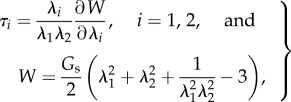
The membrane of a coating bubble or an encapsulated liposome is usually very thin of O(1–10) nm and soft, made of a polymer shell or liposome (an artificially prepared cellular entity). It is assumed to be infinitely thin and isotropic in their planes. The elasticity of the membrane can be described by the Mooney–Rivlin law [46]
 |
3.1 |
where λ1 and λ2 are the principal stretches, τ1 and τ2 are the corresponding in-plane tensions, and Gs is the surface modulus of elasticity. As cellular deformations, coated micro-bubbles or liposomes subject to ultrasound exposure normally exhibit viscoelastic behaviours in their deformations and hence a more compressive model which includes the viscoelasicity has been introduced recently [47]. The following term should be added to equation (3.1) for producing the constitutive equations of a viscoelastic material:
| 3.2 |
where μs is the surface modulus of viscosity and  is the tensions contributed by viscosity. Alternately, the membrane of encapsulated liposome can be portrayed by cell mechanical models which are described in detail in the following section.
The transverse shear tension q is given in terms of the bending moment m expressed in a similar form to that of the in-plane stress [15]. The membrane stress is then given as
| 3.3 |
The governing equations for the coating
| 3.4 |
where pb is the pressure of the bubble and κ the curvature of the surface. We is the Weber number We = R0p0/σ. We assume that the shear stress of the gas on the coating is negligible, as viscosity of gases is much smaller than that of liquids.
There has been substantial progress in the coupled dynamics between an uncoated bubble and viscoelastic surface [48,49]. Studies of bubbles near cells have been carried out by Van Wamel et al. [50] and Prentice et al. [51]. The BIM model described in §2 can be developed to model the interaction of coated bubble dynamics and coating membrane dynamics. At each step, the stress distributions Fn and Fτ are provided from the fluid modelling, and the membrane modelling will then provide the velocity distribution of the coating or liposome membrane, which are subsequently used as the inputs for the fluid modelling.
4. Cell mechanics models
Deformation of a biological cell is a complex interplay between the interfacial, mechanical and viscoelastic components such as filaments, extracellular matrix and membranous organelles, their distinct geometry and characteristics, the microstructure within the cell and the concerted deformation of each component in response to external load. To determine these parameters, a comprehensive biomechanical model is necessary to extract the information from measurements such as Poisson's ratio, Young's modulus, internal pressure, bursting strength, viscoelasticity, etc. The model is also expected to relate these intrinsic materials properties to the macroscopic manifestation of the overall cellular deformation behaviours. Since most biomimetic/biological cells comprise nonlinear, inhomogeneous, anisotropic and viscoelastic materials, their constitutive laws and the embedded stress–strain relationships cannot be adequately described by conventional linear elasticity. Large deformation theory, in conjunction with the nonlinear Moony–Rivlin constitutive equations, is adopted for polymeric vesicle or microbubble shown as equation (3.1) [52], while liposome mechanical model is best suited for describing specifically deformation of liposome or lipid-coated bubble in various situations [53]. The existing models are apparently inadequate to portray an actual biological cell in full details, except certain specific simple structures such as mature erythrocytes which possess neither organelles nor nuclei within the cell membrane. The latest drive is to develop appropriate theoretical models which include the large deformation formulation, nonlinear elasticity and viscosity. These higher order models are obviously more comprehensive than most of the previously reported studies which belong to first-order analyses.
4.1. Elastic shell model
Mechanical models for describing the mechanics of liposomes or coated bubbles have been long endeavoured and resulted in two major categories: bending stiffness dominating [54] and extensional modulus dominating [55]. The former describes a cell as a thin spherical elastic membrane filled with liquid or air, similar to a balloon, while the latter portrays a cell membrane as a rigid thick shell. Based on these developments, a model which combines both of the extensional and bending effects has been developed for analysing liposome deformation induced by pressure change [56]. It is worth pointing out that liposome possesses surface and mechanical behaviours similar to biological cells and hence several cell mechanical models are developed based on the study of liposome mechanics [57,58].
Liposome is considered as a spherical vesicle with a permeable wall composed of a lipid bilayer membrane, and the deformation is determined as a function of in-plane shear modulus, H, in combination with out-of-plane bending modulus, B. A dimensionless parameter, C = a2H/B, was introduced for the combined effects of in-plane shear (H) and out-of-plane bending (B) when a single red blood cell under specific loading configurations [57].
Similar to equation (3.1), the liposome model was developed based on the large strain formula and can be expressed as
| 4.1 |
and
| 4.2 |
where  and
and  are non-dimensional resultant tensile forces across the membrane thickness in any infinitesimal element, and λ is principal stretch. The non-dimensional parameter C = R02H/B expresses the relative strengths of the in-plane shear modulus H (N m–1) and out-of-plane bending modulus B (N m–1) for a liposome of original radius R0. This important parameter governs the deformed geometry of liposome and cell membranes.
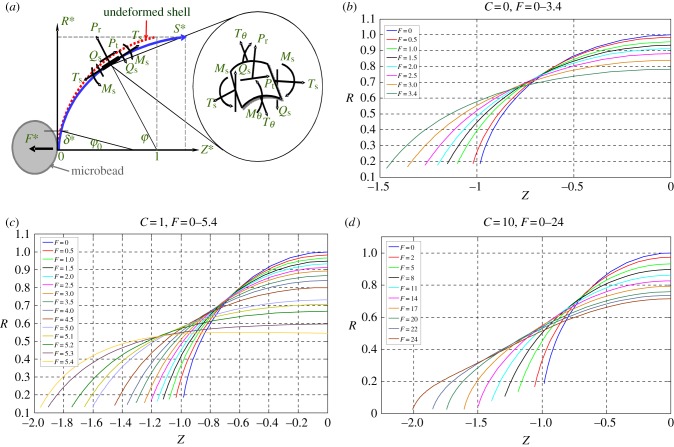
The models have been demonstrated to be able simulate the cell deformation under various external loadings [57,58]. An example of the applications is to simulate the deformation of a bead-attached erythrocyte cell stretched by a point force F at the equator; its detailed experimental is described in §5.2 (figure 10b) [59]. For such a case, three governing equations were developed to describe geometric relationships (figure 8a) as shown in the following:
| 4.3 |
| 4.4 |
| 4.5 |
Figure 10.
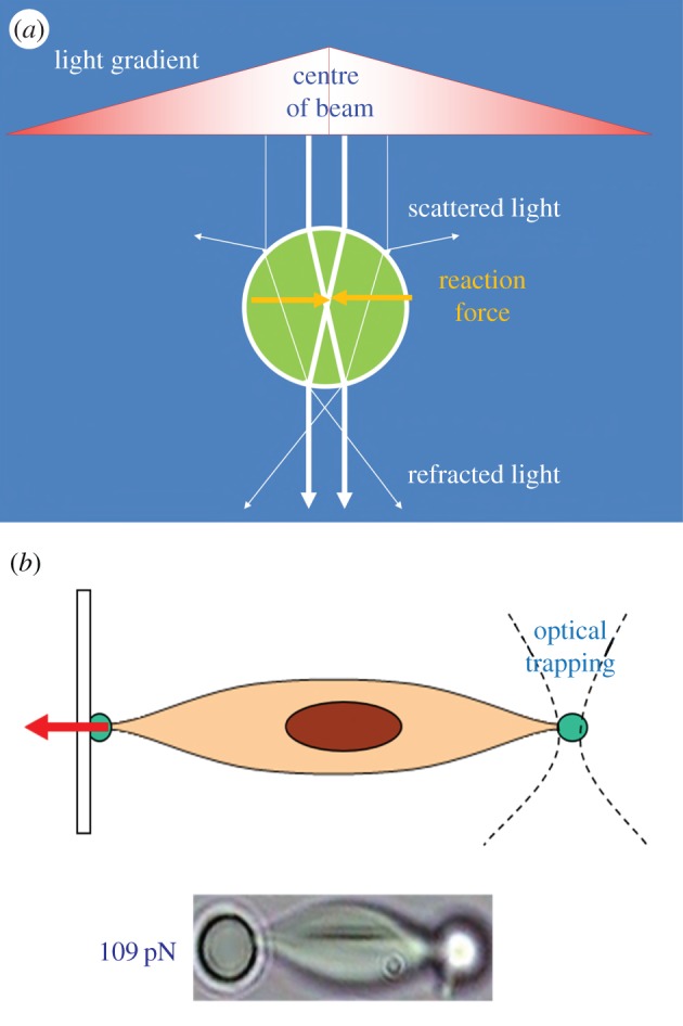
(a) Schematic of working principle of OT. (b) Using OT for stretching a single cell for mechanical characterization. (Online version in colour.)
Figure 8.
(a) Cell membrane under deformation described by liposome model. (b–d) The simulated meridional profiles of the cell membrane following deformation in the Z direction, shown for C = 0–10. (Online version in colour.)
The other three equations were used to describe balance of bending moment, shearing and tensile forces as shown below:
| 4.6 |
| 4.7 |
 |
4.8 |
If the deformation is assumed to be axisymmetric, the basic boundary conditions are
| 4.9 |
and
| 4.10 |
The simulated deformation of a liposome stretched by applied force F for various C ranging from 0 to 10 is shown in figure 8b–d. It is envisaged this mechanical model has a great potential for integration with fluid mechanical model for cell–flow interaction simulation.
4.2. Elastic solid model
Atomic force microscopy (AFM) indentation was used to measure turgor pressure and surface properties of a single biological cell [60,61], and the elasticity of cell membranes [62]; the experimental is mentioned in §5.1. Recently, the technique has been applied to characterize elastic modulus of lipid encapsulated microbubbles [63]. Elastic mechanical models, though contradictory sometimes to viscoelastic models, were developed to estimate the materials properties. Among these, Hertz contact model is the most prevailing to analyse the force–displacement curves acquired by indentation experiments. Briefly, when a cell is indented by a spherical probe, the force F applied on the cell can be described as function of indentation depth δ as follows:
| 4.11 |
and
| 4.12 |
where E and v are Young's modulus and Poisson's ratio of the cell, respectively, α is the radius of indenter–cell contact area, and RS is the radius of the spherical tip. The Hertz model is only valid for indentations up to 10% of the sample height, and substrate effects are considered negligible [64].
4.3. Viscoelatic solid model
Having taken into account viscoelasticity of biological cells, Darling et al. [65] have developed a simple model in which a standard linear solid was integrated with the Hertz equation for modelling small deformation of an isotropic, incompressible solid sphere indented by a hard spherical indenter. The model has been used to characterize the viscoelastic properties of zonal articular chondrocytes. The concise form of the final constitutive relation of the cell is given by
| 4.13 |
where F(t) is the time-dependent indentation force, δ is the indentation depth, ER is the relaxation elastic modulus, τσ and τɛ are the relaxation times under constant load and constant strain, respectively.
Roca-Cusachs et al. [66] have developed an alternative viscoelastic model for AFM indentation of cells. They developed force–displacement relationships based on Kelvin viscoelastic model body as
| 4.14 |
where Ei is Young's modulus of the interior of the cell, T is cortical tension and rt is the radius of the AFM tip. Viscoelasticity is then incorporated into the model through converting the shear modulus G = E/2(1 + ν) into the frequency domain as
| 4.15 |
with
 |
4.16 |
| 4.17 |
where f is the angular frequency, δo is approximate depth around an indentation point, iωb(0) is the correction for the viscous drag force exerted by the liquid medium on the AFM cantilever.
5. Experimental techniques
Properties of the coatings of microbubbles, such as their thickness and elasticity, vary significantly among various types of UCAs. For example, lipid coatings (e.g. Sonovue®, Definity®) have a typical thickness of 1–5 nm, thin-shelled protein contrast agents (e.g. Albunex®) have a shell thickness of about 15 nm, while some thick-shelled protein and polymer bubbles (e.g. Quantison™) have coatings 200–300 nm in thickness.
The elastic modulus and viscosity of the encapsulating shell material are two critical parameters for the response of UCAs or liposome subject to ultrasound and ultimately dictate their biomedical performance. Conventional acoustic technique has been long applied to measure scattering and attenuation of ultrasound field passing a suspension solution of echogenic microbubble or liposome [67,68]. The viscoelastic properties of the vesicles can be therefore determined indirectly through fitting the experimental results with the data predicted by well-known theories such as Church model [69] or Hoff model [70]. De Jong & Hoff [71] obtained values for the shear and elastic moduli of human serum albumin to characterize Albunex® microbubbles. These values also have been used to study the dynamics of Optison® microbubbles [6]. Using similar methods, Gorce et al. [72] estimated the stiffness and viscosity of a phospholipid coating of the contrast agent Sonovue® obtaining a shear modulus, Gs, of approximately 122 MPa and shell viscosity, μs, of approximately 2.5 Pa · s, while for albumin coatings (e.g. Albunex®), values for the shear modulus and viscosity of 88.8 MPa and 1.77 Pa · s, respectively, have been reported. By contrast, Postema et al. [73] have reported a much lower value of the elastic modulus for Albunex®, Quantison™ and Sonovue® contrast agents (E = 2 MPa, from which assuming Poisson ratio of 0.5, one can estimate  ). For an experimental contrast agent with a polymer coating from Nycomed (mean diameter approx. 6 µm and shell thickness approx. 5% of the particle radius), Hoff et al. [70] reported a shear modulus of 10.6–12.9 MPa and a shell viscosity of 0.39–0.49 Pa · s.
Although the acoustic characterization technique allows one to measure these mechanical properties, challenges in experimental set-ups remain in the attempts to directly measure applied force and corresponding deformation for a single microbubble or liposome for accurate determination of its membrane elastic modulus and viscosity. Typical mechanical forces acting on a single bubble or liposome range from hundreds of piconewtons (pN) to hundreds of micronewtons (µN). It is therefore necessary to develop appropriate ultrasensitive force–displacement measurement instruments for empirical studies. Thanks to the recent advancements in micro-/nano-mechanical force sensing devices, tremendous improvements were made by a spectrum of instruments. These techniques include micropipette technique [74], optical tweezers (OT) [75], AFM [63] and micro-compression technique [76]. Among these, AFM and OT are the most accurate and prevailing techniques. The former is due to its excellent capabilities of simultaneous measurements of both deformation and applied force, while the latter owing to its non-contact and cell friendly nature. Other popular methods include compression method which has various formats in terms of its instrumentation such as micromanipulation method and the so-called ‘cell-poking’ technique [77], micropipette aspiration method [78], magnetic tweezers [79], etc.
5.1. Atomic force microscopy
AFM mainly comprises an ultrasensitive cantilever attached with a probe at its end and a laser beam reflected to a photodetector by the deflection position of the end of the cantilever for measuring the probe–surface interaction (figure 9). AFM is capable of applying compressive force via the probe to indent a single cell or coated bubble so that the materials parameters can be determined based on the analyses of the force–displacement curves obtained during the cell deformation [80]. Latest advances in life sciences and biomimetics have put the AFM indentation technique in the central stage to investigate biomechanics of both biological and artificial cellular entities. Many single-cell mechanics studies were reported using this technique in the past decade due to its ultrasensitive capability (ca 1 pN in force resolution) and wide force range (5 pN to 10 000) [80]. For instance, Abou-Saleh et al. [63] used AFM to compress lipid encapsulated microbubbles to a large deformation (50%) for both uncoated bubbles and coated with protein (streptavidin) or the addition of quantum dots for determination of their mechanical properties. Chen et al. [81] have applied AFM to study stiffness of phospholipid-coated microbubbles and found the stiffness decreased exponentially with the microbubble size; thus the finding provided useful insights into cavitation-induced drug delivery. Mahalingam et al. [82] studied the compression stiffness of bovine serum albumin (BSA)-stabilized microbubbles through AFM nanoindentation and found that the stiffness of the microbubbles increased with the increase of the concentration of BSA solution.
Figure 9.
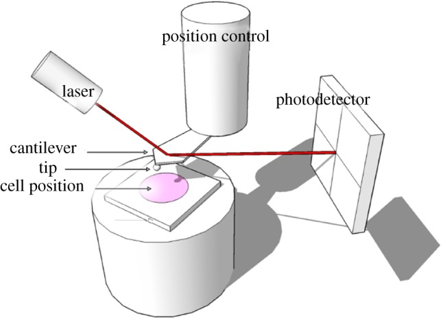
Schematic of AFM to indent a single cell for mechanical characterization. (Online version in colour.)
5.2. Optical tweezers
OT are a technique to apply non-contact mechanical force to trap particles by using the radiation pressure which is originated from electromagnetic field (figure 10a). From microscopic point of view, the trapping force is created by the momentum change of photons through a medium or lens. A focused laser beam hitting the particles with a comparatively higher refractive index than the surrounding medium is able to generate a trapping force ranging from 0.1 to 100 pN [75]. The technique has several unique advantages including non-contact, cell-friendly and ultra-high force resolution for studying single-cell mechanics [83]. More importantly, OT are able to manipulate cells within liquid medium which makes it the most suitable technique to study cellular mechanical behaviours in cavitation flow [84]. Recently, OT have emerged as a novel tool for manipulating single biological cells and performing sophisticated biomechanical characterizations such as studying the mechanics of a single liposome [85] as well as characterizing the mechanical properties of single biological cells [86]. Normally, two diametrically opposed silica beads (a few micrometres in diameter) are attached on the cell surface as ‘handles’, through which optical trap force can be applied to deform the cell (figure 10b). Combined with appropriate mechanical models (e.g. elastic shell model described in §4.1), the mechanical properties of the cell can be determined based on the degree of cell deformation versus the applied trapped force. For biological cell trapping, a wavelength of 1064 nm is often chosen to minimize the absorption by water and cytoskeleton and to avoid possible thermal damage of the trapped cells. Recently, OT have also been applied to study the mechanics of microbubbles. For example, Garbin et al. [87] used OT combined with an ultrahigh-speed camera to study the burst and oscillation of a microbubble subject to ultrasonic stimulation and how the interface and neighbouring bubbles influence its dynamic behaviours. Jones et al. [88] used scanning OT to trap UCA microbubbles and measured the transverse drag force which has been found to decrease significantly at small trap radii.
5.3. Compression method
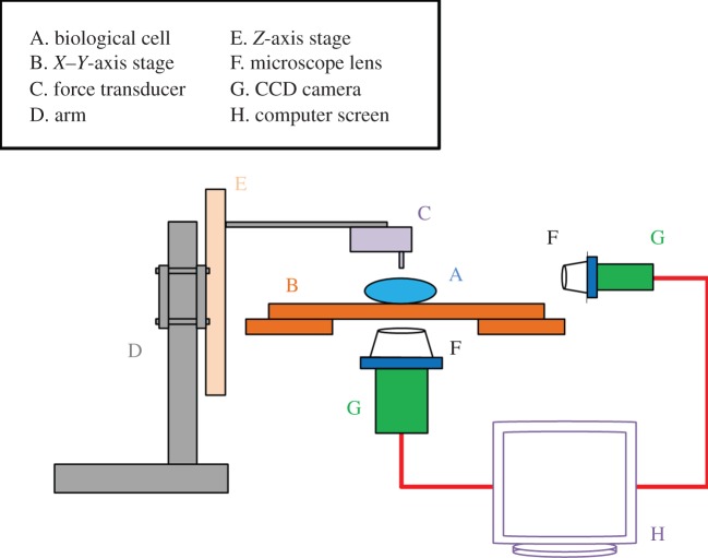
Compression method is to press against a single cell between two parallel plates deforming it into two planar contact circles with the substrates and a torus surface. This method has been applied for a wide spectrum of biological cells. Cole [89] applied known compressive mechanical forces to deform sea-urchin egg cells and the tensile stress of cell membrane is thus determined based on the subsequent deformed geometry. Adopting a similar compression technique, Zhang et al. [90] developed a micromanipulation technique to press single cells and measured simultaneously the applied force and the sample deformed geometry. The tension modulus and bursting strength were determined using the technique combined with a simple mathematical model. The main challenge in using the parallel plate compression device is that it requires a high precision positioning of the plate movement which is difficult to achieve. Besides, there is no experimental technique which allows continuous measurement of force–displacement curve for the cell during loading/unloading deformation cycles. Later Liu et al. [76] developed a micro-compression instrument which employed an ultra-precision micro-stepping motor and force transducer to achieve the continuous compliance measurement of a single cellular entity under compressive deformation. The in situ deformation of the cell sample and its instant equatorial diameter were also visualized by a CCD-enhanced microscope system (figure 11). The instrument has an ultimate resolution of force and displacement of 10 nN and 10 nm, respectively. The technique has been applied to measure the membrane mechanical properties of both biological and non-biological vesicles (e.g. microcapsule) [91].
Figure 11.
Schematic diagram of cell characterization instrument set-up (not to scale). (Online version in colour.)
5.4. Nanoindentation method
Daily et al. [77] and Zahalak et al. [92] developed a cell indentation method which involves indenting biological cells with a micro-radius tip (ca 2 µm) to measure the loading–unloading responses. In principle, this indentation technique is an extension of the compliance method. There are several possible drawbacks of the method when applying it to a cell that comprises a thin lipid bilayer encapsulating an aqueous content (e.g. cytoplasm). Firstly, indentation provides useful localized mechanical properties only if the indent dimension is small compared with the size of the sample cell at least by a factor of 10, such that the sample resembles a continuum half space. This requirement seems to be violated in the reported experiments by Daily et al. [77] and Zahalak et al. [92]. Furthermore, it is an established fact in the literature that when the indentation depth exceeds 10% of the surface film thickness, deformation of the film substrate may be no longer negligible, let alone the inevitable membrane stretching. Such intractable problem further exacerbates in the case of small cells where the sample volume remains virtually constant even upon an external load. More importantly, the observed deformation characteristics can be a very strong but unknown function of the precise geometry of the indenter. These factors present a degree of difficulty in the analysis of measured data for determination of materials parameters.
6. Perspectives
We review an interdisciplinary technique that includes biomechanical testing techniques to determine mechanical properties of single coated microbubbles and a theoretical model incorporated with the determined parameters to simulate the bubble dynamics. The deformation of bubble-coating membrane can be modelled based on Mooney's hyperelastic constitutive law. However, cell mechanical model may be applied for better describing the lipid membrane of liposome and cell. This technique has important perspectives in studying the following phenomena: (i) the breaking of the bubble coating in releasing drug/gene, (ii) the resultant alteration of cell porosity and permeability, (iii) the role of deformation and jetting from coated bubbles, (iv) non-spherical shape oscillation of coated bubbles at various mode numbers and (v) microstreaming around cells due to microbubble oscillation. These fundamental mechanisms remain elusive, are all associated with non-spherical effects and therefore can be expected to be captured only by models using non-spherical bubble dynamics in combination with cell mechanics. Moreover, since both the coated microbubble and biological cell exhibit viscoelastic behaviours, viscoelasticity should be taken into account in the future simulation of their deformations and dynamics. The effects of different bubble sizes and location, coatings and membranes (thickness and material) and wave parameters (frequency, wavelength, amplitude and profile) should be thoroughly studied to access the optimum properties for drug delivery and sonoporation.
Competing interests
We declare we have no competing interests.
Funding
We received no funding for this study.
References
- 1.Coussios CC, Roy RA. 2008. Applications of acoustics and cavitation to noninvasive therapy and drug delivery. Annu. Rev. Fluid Mech. 40, 395–420. ( 10.1146/annurev.fluid.40.111406.102116) [DOI] [Google Scholar]
- 2.Yu H, Xu L. 2014. Cell experimental studies on sonoporation: state of the art and remaining problems. J. Controlled Release 174, 151–160. ( 10.1016/j.jconrel.2013.11.010) [DOI] [PubMed] [Google Scholar]
- 3.Tsutsui JM, Xie F, Porter RT. 2004. The use of microbubbles to target drug delivery. Cardiovasc. Ultrasound 2, 23 ( 10.1186/1476-7120-2-23) [DOI] [PMC free article] [PubMed] [Google Scholar]
- 4.Sirsi SR, Borden MA. 2009. Microbubble compositions, properties and biomedical applications. Bubble Sci. Eng. Technol. 1, 3–17. ( 10.1179/175889709X446507) [DOI] [PMC free article] [PubMed] [Google Scholar]
- 5.Rodríguez-Rodríguez J, Sevilla A, Martínez-Bazán C, Gordillo JM. 2015. Generation of microbubbles with applications to industry and medicine. Annu. Rev. Fluid Mech. 47, 405–429. ( 10.1146/annurev-fluid-010814-014658) [DOI] [Google Scholar]
- 6.Stride E, Saffari N. 2003. Microbubble ultrasound contrast agents: a review. J. Eng. Med. 217, 429–447. ( 10.1243/09544110360729072) [DOI] [PubMed] [Google Scholar]
- 7.Dindyal S, Kyriakides C. 2011. Ultrasound microbubble contrast and current clinical applications. Recent Pat. Cardiovasc. Drug Discov. 6, 27–41. ( 10.2174/157489011794578446) [DOI] [PubMed] [Google Scholar]
- 8.Ibsen S, Schutt CE, Esener S. 2013. Microbubble-mediated ultrasound therapy: a review of its potential in cancer treatment. Drug Design Dev. Therapy 7, 375–388. ( 10.2147/DDDT.S31564) [DOI] [PMC free article] [PubMed] [Google Scholar]
- 9.Carson AR, et al. 2011. Gene therapy of carcinoma using ultrasound-targeted microbubble destruction. Ultrasound Med. Biol. 37, 393–402. ( 10.1016/j.ultrasmedbio.2010.11.011) [DOI] [PMC free article] [PubMed] [Google Scholar]
- 10.Kaul S. 2004. Microbubbles and ultrasound: a bird's eye view. Trans. Am. Clin. Climatol. Assoc. 115, 137–148. [PMC free article] [PubMed] [Google Scholar]
- 11.Shen ZP, Brayman AA, Chen L, Miao CH. 2008. Ultrasound with microbubbles enhances gene expression of plasmid DNA in the liver via intraportal delivery. Gene Therapy 15, 1147–1155. ( 10.1038/gt.2008.51) [DOI] [PMC free article] [PubMed] [Google Scholar]
- 12.Marmottant P, Hilgenfeldt S. 2003. Controlled vesicle deformation and lysis by single oscillating bubbles. Nature 423, 153–156. ( 10.1038/nature01613) [DOI] [PubMed] [Google Scholar]
- 13.Ferrara K, Pollard R, Borden M. 2007. Ultrasound microbubble contrast agents: fundamentals and application to gene and drug delivery. Annu. Rev. Biomed. Eng. 9, 415–447. ( 10.1146/annurev.bioeng.8.061505.095852) [DOI] [PubMed] [Google Scholar]
- 14.Postema M, van Wamel A, Lancée CT, de Jong N. 2004. Ultrasound-induced encapsulated microbubble phenomena. Ultrasound Med. Biol. 30, 827–840. ( 10.1016/j.ultrasmedbio.2004.02.010) [DOI] [PubMed] [Google Scholar]
- 15.Liu Y, Sugiyama K, Takagi S, Matsumoto Y. 2012. Surface instability of an encapsulated bubble induced by an ultrasonic pressure wave. J. Fluid Mech. 691, 315–340. ( 10.1017/jfm.2011.477) [DOI] [Google Scholar]
- 16.Chen H, Kreider W, Brayman AA, Bailey MR, Matula TJ. 2011. Blood vessel deformations on microsecond time scales by ultrasonic cavitation. Phys. Rev. Lett. 106, 034301 ( 10.1103/PhysRevLett.106.034301) [DOI] [PMC free article] [PubMed] [Google Scholar]
- 17.Paul S, Nahire R, Mallik S, Sarkar K. 2014. Encapsulated microbubbles and echogenic liposomes for contrast ultrasound imaging and targeted drug delivery. Comput. Mech. 53, 413–435. ( 10.1007/s00466-013-0962-4) [DOI] [PMC free article] [PubMed] [Google Scholar]
- 18.Schroeder A, Kost J, Barenholz Y. 2009. Ultrasound, liposomes, and drug delivery: principles for using ultrasound to control the release of drugs from liposomes. Chem. Phys. Lipids 162, 1–16. ( 10.1016/j.chemphyslip.2009.08.003) [DOI] [PubMed] [Google Scholar]
- 19.Sundaram J, Mellein BR, Mitragotri S. 2003. An experimental and theoretical analysis of ultrasound-induced permeabilization of cell membranes. Biophys. J. 84, 3087–3101. ( 10.1016/S0006-3495(03)70034-4) [DOI] [PMC free article] [PubMed] [Google Scholar]
- 20.Guerri L, Lucca G, Prosperetti A. 1981. A numerical method for the dynamics of nonspherical cavitation bubbles. In Proc. 2nd Int. Colloquium on Drops and Bubbles, California NASA JPL Publications 82-7, p. 175. Pasadena, CA: California Institute of Technology.
- 21.Blake JR, Taib BB, Doherty G. 1986. Transient cavities near boundaries. Part 1. Rigid boundary. J. Fluid Mech. 170, 479–497. ( 10.1017/S0022112086000988) [DOI] [Google Scholar]
- 22.Blake JR, Taib BB, Doherty G. 1987. Transient cavities near boundaries. Part 2. Free surface. J. Fluid Mech. 181, 197–212. ( 10.1017/S0022112087002052) [DOI] [Google Scholar]
- 23.Brujan EA, Keen GS, Vogel A, Blake JR. 2002. The final stage of the collapse of a cavitation bubble close to a rigid boundary. Phys. Fluids 14, 85–92. ( 10.1063/1.1421102) [DOI] [Google Scholar]
- 24.Szeri AJ, Storey BD, Pearson A, Blake JR. 2003. Heat and mass transfer during the violent collapse of nonspherical bubbles. Phys. Fluids 15, 2576–2586. ( 10.1063/1.1595647) [DOI] [Google Scholar]
- 25.Wang QX, Yeo KS, Khoo BC, Lam KY. 1996. Nonlinear interaction between gas bubble and free surface. Comput. Fluids 25, 607–628. ( 10.1016/0045-7930(96)00007-2) [DOI] [Google Scholar]
- 26.Wang QX, Yeo KS, Khoo BC, Lam KY. 1996. Strong interaction between buoyancy bubble and free surface. Theor. Comput. Fluid Dyn. 8, 73–88. ( 10.1007/BF00312403) [DOI] [Google Scholar]
- 27.Wang QX, Yeo KS, Khoo BC, Lam KY. 2005. Vortex ring modelling for toroidal bubbles. Theor. Comput. Fluid Dyn. 19, 303–317. ( 10.1007/s00162-005-0164-6) [DOI] [Google Scholar]
- 28.Lind SJ, Phillips TN. 2012. The influence of viscoelasticity on the collapse of cavitation bubbles near a rigid boundary. Theor. Comput. Fluid Dyn. 26, 245–277. ( 10.1007/s00162-011-0227-9) [DOI] [Google Scholar]
- 29.Curtiss GA, Leppinen DM, Wang QX, Blake JR. 2013. Ultrasonic cavitation near a tissue layer. J. Fluid Mech. 730, 245–272. ( 10.1017/jfm.2013.341) [DOI] [Google Scholar]
- 30.Wang QX. 1998. The numerical analyses of the evolution of a gas bubble near an inclined wall. Theor. Comput. Fluid Dyn. 12, 29–51. ( 10.1007/s001620050097) [DOI] [Google Scholar]
- 31.Wang QX. 2004. Numerical modelling of violent bubble motion. Phys. Fluids 16, 1610–1619. ( 10.1063/1.1704645) [DOI] [Google Scholar]
- 32.Klaseboer E, Fong SW, Turangan CK, Khoo BC, Szeri AJ, Calvisi ML, Sankin GN, Zhong P. 2007. Interaction of lithotripter shockwaves with single inertial cavitation bubbles. J. Fluid Mech. 593, 33–56. ( 10.1017/S002211200700852X) [DOI] [PMC free article] [PubMed] [Google Scholar]
- 33.Jayaprakash A, Singh S, Chahine G. 2011. Experimental and numerical investigation of single bubble dynamics in a two-phase bubbly medium. J. Fluids Eng. 133, 121305 ( 10.1115/1.4005424) [DOI] [Google Scholar]
- 34.Wang QX, Blake JR. 2010. Non-spherical bubble dynamics in a compressible liquid. Part 1. Travelling acoustic wave. J. Fluid Mech. 659, 191–224. ( 10.1017/S0022112010002430) [DOI] [Google Scholar]
- 35.Wang QX, Blake JR. 2011. Non-spherical bubble dynamics in a compressible liquid. Part 2. Acoustic standing wave. J. Fluid Mech. 679, 559–581. ( 10.1017/jfm.2011.149) [DOI] [Google Scholar]
- 36.Wang QX. 2013. Non-spherical bubble dynamics of underwater explosions in a compressible fluid. Phys. Fluids 25, 072104 ( 10.1063/1.4812659) [DOI] [Google Scholar]
- 37.Wang Q. 2014. Multi-oscillations of a bubble in a compressible liquid near a rigid boundary. J. Fluid Mech. 745, 509–536. ( 10.1017/jfm.2014.105) [DOI] [Google Scholar]
- 38.Johnsen E, Colonius T. 2009. Numerical simulations of non-spherical bubble collapse. J. Fluid Mech. 629, 231–262. ( 10.1017/S0022112009006351) [DOI] [PMC free article] [PubMed] [Google Scholar]
- 39.Yang B, Prosperetti A. 2008. Vapour bubble collapse in isothermal and non-isothermal liquids. J. Fluid Mech. 601, 253–279. ( 10.1017/S0022112008000670) [DOI] [Google Scholar]
- 40.Turangan CK, Jamaluddin AR, Ball GJ, Leighton TG. 2008. Free-Lagrange simulations of the expansion and jetting collapse of air bubbles in water. J. Fluid Mech. 598, 1–25. ( 10.1017/S0022112007009317) [DOI] [Google Scholar]
- 41.Yue P, Feng JJ, Bertelo CA, Hu HH. 2007. An arbitrary Lagrangian–Eulerian method for simulating bubble growth in polymer foaming. J. Comput. Phys. 226, 2229–2249. ( 10.1016/j.jcp.2007.07.007) [DOI] [Google Scholar]
- 42.Hua J, Lou J. 2007. Numerical simulation of bubble rising in viscous liquid. J. Comput. Phys. 222, 769–795. ( 10.1016/j.jcp.2006.08.008) [DOI] [Google Scholar]
- 43.Hsiao CT, Chahine GL. 2013. Breakup of finite thickness viscous shell microbubbles by ultrasound: a simplified zero-thickness shell model. J. Acoust. Soc. Am. 133, 1897–1910. ( 10.1121/1.4792492) [DOI] [PMC free article] [PubMed] [Google Scholar]
- 44.Hoff L. 2001. Acoustic characterization of contrast agents for medical ultrasound imaging. Dordrecht, The Netherlands: Kluwer. [Google Scholar]
- 45.Wang QX, Manmi K. 2014. Three dimensional microbubble dynamics near a wall subject to high intensity ultrasound. Phys. Fluids 26, 032104 ( 10.1063/1.4866772) [DOI] [Google Scholar]
- 46.Tsigklifis K, Pelekasis NA. 2013. Simulations of insonated contrast agents: saturation and transient break-up. Phys. Fluids 25, 032109 ( 10.1063/1.2061872) [DOI] [Google Scholar]
- 47.Doinikov AA, Haac JF, Dayton PA. 2009. Modeling of nonlinear viscous stress in encapsulating shells of lipid-coated contrast agent microbubbles. Ultrasonics 49, 269–275. ( 10.1016/j.ultras.2008.09.007) [DOI] [PMC free article] [PubMed] [Google Scholar]
- 48.Brujan E, Nahen K, Schmidt P, Vogel A. 2001. Dynamics of laser-induced cavitation bubbles near an elastic boundary. J. Fluid Mech. 433, 251–281. ( 10.1017/S0022112000003347) [DOI] [Google Scholar]
- 49.Brujan E, Nahen K, Schmidt P, Vogel A. 2001. Dynamics of laser-induced cavitation bubbles near elastic boundaries: influence of the elastic modulus. J. Fluid Mech. 433, 283–314. ( 10.1017/S0022112000003335) [DOI] [Google Scholar]
- 50.van Wamel A, Bouakaz A, Versluis M, de Jong N. 2004. Micromanipulation of endothelial cells: ultrasound-microbubbles-cell interaction. Ultrasound Med. Biol. 30, 1255–1258. ( 10.1016/j.ultrasmedbio.2009.06.1091) [DOI] [PubMed] [Google Scholar]
- 51.Prentice P, Cuschieri A, Dholakia K, Prausnitz M, Campbell P. 2005. Membrane disruption by optically controlled microbubble cavitation. Nat. Phys. 1, 107–110. ( 10.1038/nphys148) [DOI] [Google Scholar]
- 52.Barthes-Biesel D. 2003. Flow induced capsule deformation. In Modeling and simulation of capsules and biological cells (ed. Pozrikidis C.), pp. 1–30. London, UK: Chapman and Hall. [Google Scholar]
- 53.Li C, Liu YP, Liu KK, Lai ACK. 2006. The deformation of an erythrocyte under the radiation pressure by optical stretch.· J. Biomech. Eng. 128, 830–836. ( 10.1115/1.2354204) [DOI] [PubMed] [Google Scholar]
- 54.Waugh RE, Song J, Svetina S, Zeks B. 1992. Local and nonlocal curvature elasticity in bilayer membranes by tether formation from lecithin vesicles. Biophys. J. 61, 974–982. ( 10.1016/S0006-3495(92)81904-5) [DOI] [PMC free article] [PubMed] [Google Scholar]
- 55.Skalak R, Tozeren A, Zarda RP, Chien S. 1973. Strain energy function of red blood cell membranes. Biophys. J. 13, 245–264. ( 10.1016/S0006-3495(73)85983-1) [DOI] [PMC free article] [PubMed] [Google Scholar]
- 56.Pamplona DC, Calladine CR. 1993. The mechanics of axially symmetric liposomes. J. Biomech. Eng. 115, 149–159. ( 10.1115/1.2894115) [DOI] [PubMed] [Google Scholar]
- 57.Parker KH, Winlove CP. 1999. The deformation of spherical vesicles with permeable, constant-area membranes: application to the red blood cell. Biophys. J. 77, 3096–3107. ( 10.1016/S0006-3495(99)77140-7) [DOI] [PMC free article] [PubMed] [Google Scholar]
- 58.Foo JJ, Chan V, Liu KK. 2006. Coupling bending and shear effects on liposome deformation. J. Biomech. 39, 2338–2343. ( 10.1016/j.jbiomech.2005.07.008) [DOI] [PubMed] [Google Scholar]
- 59.Li C, Liu YP, Liu KK, Lai AC. 2008. Correlations between the experimental and numerical investigations on the mechanical properties of erythrocyte by laser stretching. NanoBiosci. IEEE Trans. 7, 80–90. ( 10.1109/TNB.2008.2000152) [DOI] [PubMed] [Google Scholar]
- 60.Arnoldi M, Fritz M, Baeuerlein E, Radmacher M, Sackmann E, Boulbitch A. 2000. Bacterial turgor pressure can be measured by atomic force microscopy. Phys. Rev. E 62, 1034–1044. ( 10.1103/PhysRevE.62.1034) [DOI] [PubMed] [Google Scholar]
- 61.Yao X, Walter J, Burke S, Stewart S, Jericho MH, Pink D, Hunter R, Beveridge TJ. 2002. Atomic force microscopy and theoretical considerations of surface properties and turgor pressures of bacteria. Colloids Surf. B 23, 213–230. ( 10.1016/S0927-7765(01)00249-1) [DOI] [Google Scholar]
- 62.Radmacher M, Fritz M, Kacher CM, Cleveland JP, Hansma PK. 1996. Measuring the viscoelastic properties of human platelets with the atomic force microscope. Biophys. J. 70, 556–567. ( 10.1016/S0006-3495(96)79602-9) [DOI] [PMC free article] [PubMed] [Google Scholar]
- 63.Abou-Saleh RH, Peyman SA, Critchley K, Evans SD, Thomson NH. 2013. Nanomechanics of lipid encapsulated microbubbles with functional coatings. Langmuir 29, 4096–4103. ( 10.1021/la304093t.) [DOI] [PubMed] [Google Scholar]
- 64.Siamantouras E, Hills CE, Younis MYG, Squires PE, Liu KK. 2014. Quantitative investigation of calcimimetic R568 on beta cell adhesion and mechanics using AFM single-cell force spectroscopy. FEBS Lett. 588, 1178–1183. ( 10.1016/j.febslet.2014.02.058) [DOI] [PubMed] [Google Scholar]
- 65.Darling EM, Zauscher S, Guilak F. 2006. Viscoelastic properties of zonal articular chondrocytes measured by atomic force microscopy. Osteoarthritis Cartilage 14, 571–579. ( 10.1016/j.joca.2005.12.003) [DOI] [PubMed] [Google Scholar]
- 66.Roca-Cusachs P, Almendros I, Sunyer R, Gavara N, Farré R, Navajas D. 2006. Rheology of passive and adhesion-activated neutrophils probed by atomic force microscopy. Biophys. J. 91, 3508–3518. ( 10.1529/biophysj.106.088831) [DOI] [PMC free article] [PubMed] [Google Scholar]
- 67.Sarkar K, Shi WT, Chatterjee D, Forsberg F. 2005. Characterization of ultrasound contrast microbubbles using in vitro experiments and viscous and viscoelastic interface models for encapsulation. J. Acoust. Soc. Am. 118, 539–550. ( 10.1121/1.1923367) [DOI] [PubMed] [Google Scholar]
- 68.Kopechek JA, et al. 2011. Acoustic characterization of echogenic liposomes: frequency-dependent attenuation and backscatter. J. Acoust. Soc. Am. 130, 3472–3481. ( 10.1121/1.3626124) [DOI] [PMC free article] [PubMed] [Google Scholar]
- 69.Church CC. 1995. The effects of an elastic solid surface layer on the radial pulsations of gas bubbles. J. Acoust. Soc. Am. 97, 1510–1521. ( 10.1121/1.412091) [DOI] [Google Scholar]
- 70.Hoff L, Sontum PC, Hovem JM. 2000. Oscillations of polymeric microbubbles: effect of the encapsulating shell. J. Acoust. Soc. Am. 107, 2272–2280. ( 10.1121/1.428557) [DOI] [PubMed] [Google Scholar]
- 71.de Jong N, Hoff L. 1993. Ultrasound scattering properties of Albunex microspheres. Ultrasonics 31, 175–181. ( 10.1016/0041-624X(93)90004-J) [DOI] [PubMed] [Google Scholar]
- 72.Gorce JM, Arditi M, Schneider M. 2000. Influence of bubble size distribution on the echogenicity of ultrasound contrast agents: a study of Sonovue™. Investig. Radiol. 35, 661–671. ( 10.1097/00004424-200011000-00003) [DOI] [PubMed] [Google Scholar]
- 73.Postema M, de Jong N, Schmitz G. 2005. The physics of nanoshelled microbubbles. Biomed. Tech. 50, 748–749. [Google Scholar]
- 74.Boudou T, Ohayon J, Arntz Y, Finet G, Picart C, Tracqui P. 2006. An extended modeling of the micropipette aspiration experiment for the characterization of the Young's modulus and Poisson's ratio of adherent thin biological samples: numerical and experimental studies. J. Biomech. 39, 1677–1685. ( 10.1016/j.jbiomech.2005.04.026) [DOI] [PubMed] [Google Scholar]
- 75.Zhang H, Liu KK. 2008. Optical tweezers for single cells. J. R. Soc. Interface 5, 671–690. ( 10.1098/rsif.2008.0052) [DOI] [PMC free article] [PubMed] [Google Scholar]
- 76.Liu KK, Williams DR, Briscoe BJ. 1996. Compressive deformation of a single microcapsule. Phys. Rev. E 54, 6673–6680. ( 10.1103/PhysRevE.54.6673) [DOI] [PubMed] [Google Scholar]
- 77.Daily B, Elson EL, Zahalak GI. 1984. Cell poking. Determination of the elastic area compressibility modulus of the erythrocyte membrane. Biophys. J. 45, 671–682. ( 10.1016/S0006-3495(84)84209-5) [DOI] [PMC free article] [PubMed] [Google Scholar]
- 78.Simson DA, Ziemann F, Strigl M, Merkel R. 1998. Micropipet-based pico force transducer: in depth analysis and experimental verification. Biophys. J. 74, 2080–2088. ( 10.1016/S0006-3495(98)77915-9) [DOI] [PMC free article] [PubMed] [Google Scholar]
- 79.Bausch AR, Möller W, Sackmann E. 1999. Measurement of local viscoelasticity and forces in living cells by magnetic tweezers. Biophys. J. 76, 573–579. ( 10.1016/S0006-3495(99)77225-5) [DOI] [PMC free article] [PubMed] [Google Scholar]
- 80.Vinckier A, Semenza G. 1998. Measuring elasticity of biological materials by atomic force microscopy. FEBS Lett. 430, 12–16. ( 10.1016/S0014-5793(98)00592-4) [DOI] [PubMed] [Google Scholar]
- 81.Chen CC, Wu SY, Finan JD, Morrison B III, Konofagou EE. 2013. An experimental study on the stiffness of size-isolated microbubbles using atomic force microscopy. Ultrason. Ferroelectr. Freq. Control IEEE Trans. 60, 524–534. ( 10.1109/TUFFC.2013.2594) [DOI] [PMC free article] [PubMed] [Google Scholar]
- 82.Mahalingam S, Meinders MB, Edirisinghe MJ. 2014. The formation, stability, and mechanical properties of bovine serum albumin stabilised air bubbles produced using co-axial electrohydrodynamic atomisation. Langmuir 30, 6694–6703. ( 10.1021/la5011715) [DOI] [PubMed] [Google Scholar]
- 83.Grier DG. 2003. A revolution in optical manipulation. Nature 424, 810–816. ( 10.1038/nature01935) [DOI] [PubMed] [Google Scholar]
- 84.Waleed M, Hwang SU, Kim JD, Shabbir I, Shin SM, Lee YG. 2013. Single-cell optoporation and transfection using femtosecond laser and optical tweezers. Biomed. Opt. Exp. 4, 1533–1547. ( 10.1364/BOE.4.001533) [DOI] [PMC free article] [PubMed] [Google Scholar]
- 85.Foo JJ, Liu KK, Chan V. 2004. Viscous drag of deformed vesicles in optical trap: experiments and simulations. AIChE J. 50, 249–254. ( 10.1002/aic.10023) [DOI] [Google Scholar]
- 86.Dao M, Lim CT, Suresh S. 2003. Mechanics of the human red blood cell deformed by optical tweezers. J. Mech. Phys. Solids 51, 2259–2280. ( 10.1016/j.jmps.2003.09.019) [DOI] [Google Scholar]
- 87.Garbin V, Cojoc D, Ferrari E, Di Fabrizio E, Overvelde MLJ, Van Der Meer SM, De Jong N, Lohse D, Versluis M. 2007. Changes in microbubble dynamics near a boundary revealed by combined optical micromanipulation and high-speed imaging. Appl. Phys. Lett. 90, 114103 ( 10.1063/1.2713164) [DOI] [Google Scholar]
- 88.Jones PH, Stride E, Saffari N. 2006. Trapping and manipulation of microscopic bubbles with a scanning optical tweezer. Appl. Phys. Lett 89, 081113 ( 10.1063/1.2338512) [DOI] [Google Scholar]
- 89.Cole KS. 1932. Surface forces of the Arbacia egg. J. Cell. Comp. Physiol. 1, 1–9. ( 10.1002/jcp.1030010102) [DOI] [Google Scholar]
- 90.Zhang Z, Ferenczi MA, Thomas CR. 1992. A micromanipulation technique with a theoretical cell model for determining mechanical properties of single mammalian cells. Chem. Eng. Sci. 47, 1347–1354. ( 10.1016/0009-2509(92)80280-P) [DOI] [Google Scholar]
- 91.Liu KK. 2006. Deformation behaviours of soft particles—a review. J. Phys. D: Appl. Phys 39, R189–R199. ( 10.1088/0022-3727/39/11/R01) [DOI] [Google Scholar]
- 92.Zahalak GI, McConnaughey WB, Elson EL. 1990. Determination of cellular mechanical properties by cell poking, with an application to leukocytes. J. Biomech. Eng. 112, 283–294. ( 10.1115/1.2891186) [DOI] [PubMed] [Google Scholar]


