

Abstract
We generally think of bubbles as benign and harmless and yet they can manifest the most remarkable range of physical effects. Some of those effects are the stuff of our everyday experience as in the tinkling of a brook or the sounds of breaking waves at the beach. But even these mundane effects are examples of the ability of bubbles to gather, focus and radiate energy (acoustic energy in the above examples). In other contexts that focusing of energy can lead to serious technological problems as when cavitation bubbles eat great holes through ships' propeller blades or cause a threat to the integrity of the spillways at the Hoover Dam. In liquid-propelled rocket engines, bubbles pose a danger to the stability of the propulsion system, and in artificial heart valves they can cause serious damage to the red blood cells. In perhaps the most extraordinary example of energy focusing, collapsing cavitation bubbles can emit not only sound, but also light with black body radiation temperatures equal to that of the sun (Brennen 1995 Cavitation and bubble dynamics). But, harnessed carefully, this almost unique ability to focus energy can also be put to remarkably constructive use. Cavitation bubbles are now used in a remarkable range of surgical and medical procedures, for example to emulsify tissue (most commonly in cataract surgery or in lithotripsy procedures for the reduction of kidney and gall stones) or to manipulate the DNA in individual cells. By creating cavitation bubbles non-invasively thereby depositing and focusing energy non-intrusively, one can generate minute incisions or target cancer cells. This paper will begin by briefly reviewing the history of cavitation phenomena and will end with a vision of the new horizons for the amazing cavitation bubble.
Keywords: cavitation, liposomes, ultrasound
1. Introduction
The phenomenon of cavitation was first recognized in 1885 during the sea trials of HMS Daring when, due to the previously unmatched propeller speeds, it was noted that ‘… cavities were being formed in the water … and these were the source of a great waste of power and the cause of other difficulties'. Shortly thereafter, it was found that these cavities were the cause of considerable pitting and erosion of the propeller blades. However, it was not until 1917 that Lord Rayleigh [1] provided a partial explanation by showing that great pressures could be generated during the collapse of spherical vapour bubbles. Subsequently, in the late 1930s, Robert Knapp was able to capture the behaviour of individual cavitation bubbles in now-classic movies. Those movies illustrated the high degree of nonlinearity exhibited by cavitation bubbles as they experience a low-pressure episode: as depicted schematically in figure 1 [2], while the bubble is experiencing low pressure in the surrounding liquid, the growth is relatively gentle. However, the collapse when the liquid pressure increases is catastrophic and violent. This nonlinear behaviour is captured in the Rayleigh–Plesset equation for spherical bubble dynamics (for which figure 1 is a typical solution); in such solutions, the bubble collapses to a size much smaller than its original dimension, thus compressing whatever non-condensable gas might be present in the bubble to very high pressures and temperatures. This produces some amazing side-effects such as the emission of light (sonoluminescence).
Figure 1.

A typical cavitation bubble behaviour as calculated from the Rayleigh–Plesset equation. (Online version in colour.)
Thus, energy is stored in the bubble/liquid system during the growth phase and is released and focused during the collapse phase. It is this focusing of energy in both space and time that produces some of the remarkable effects of cavitation and allows it to be used for multiple purposes. When the bubble collapses from a maximum volume much larger than that of the original nucleus, the compression of the non-condensable gas during the final stage of collapse can lead to very high values of the second derivative of the bubble volume (as depicted in figure 2). Because the radiated acoustic pressure, pa, is proportional to this second derivative,
| 1.1 |
(where ρ and  are respectively the liquid density and the distance of the pressure measurement point from the bubble centre), the collapse can radiate a very large positive pressure spike. A measure of the magnitude of this is the acoustic impulse, I, defined as the area under the measured spike or
| 1.2 |
where t1 and t2 are the times at the start and end of the large pulse. Much of the damage caused by cavitation can be attributed to the succession of these pulses. However, as demonstrated in figure 3 [3], the acoustic impulse magnitudes predicted by the Rayleigh–Plesset equation are about an order of magnitude larger than those measured experimentally, because spherical collapse is the most efficient impulse maker and deviations in the shape of actual collapsing bubbles result in less violent collapses with lower impulses. The experimental data included in figure 3 also show a greater potential for deviation from spherical shape for the larger bubbles in each of the series of individual experiments.
Figure 2.

The bubble behaviour in the final stage of collapse. (Online version in colour.)
Figure 3.

The acoustic impulse (dimensionless) plotted against the maximum bubble volume (dimensionless) prior to collapse: Rayleigh–Plesset calculations for a spherical bubble and measurements from a series of experiments on cavitation in flows. Adapted from Kuhn de Chizelle et al. [3].
Deviations from spherical shape and much more of the remarkable behaviour of collapsing cavitation bubbles were first witnessed in the 1940s by Knapp and Albert Ellis owing to their technical achievements in developing the first very high speed cameras with microsecond exposures and framing rates approaching a million per second. These revealed the detailed dynamics of individual millimetre-sized cavitation bubbles and showed that, upon collapse near a wall, the bubbles exhibited a very high speed ‘re-entrant jet’ directed at the wall as illustrated in figure 4 [4]. Further analyses showed that these ‘re-entrant jets’ could contribute to cavitation damage though later experiments and analyses showed that other potential contributors were the shockwaves generated by the collapse of the remnant cloud [5] after the passage of the re-entrant jet (figure 5) or the shockwaves generated by the collapse of larger clouds of bubbles. We now address the latter issue, namely the important collective effect of a cloud of bubbles.
Figure 4.

Photograph taken by Albert Ellis shows the formation of a re-entrant jet during collapse of a cavitation bubble near a wall. The upward inclination is the additional effect of gravity. Adapted from Benjamin & Ellis [4], reproduced with permission.
Figure 5.

The remnant bubble cloud after the passage of the re-entrant jet. From [5], reproduced with permission.
2. Cloud cavitation
As a concluding comment in this introduction to the mechanics of cavitation, we note that many of the applications described later involve the dynamics of clouds of cavitation bubbles and that there is a continuing need to proceed beyond single cavitation bubbles to understand the dynamics of such clouds. The interactions between the bubbles in these clouds generate new phenomena that may be the key to understanding the effectiveness of the cavitation tool. For example, Wang & Brennen [6,7] examined the geometrically simple case of the growth and collapse of a spherical cloud of bubbles (such as depicted in figure 6) surrounded by pure liquid. It transpires that the response of this cloud to an episode of reduced pressure in the surrounding liquid is quite different depending on the magnitude of the parameter β = αA2/R2, where α is the initial volume fraction of bubbles in the cloud and A and R are the typical linear dimensions of the cloud and the individual bubbles. When β is much greater than unity, the typical cloud response to an episode of reduced pressure is that the bubbles on the surface collapse first, and a collapse front propagates inward from the cloud surface developing into a substantial shockwave.
Figure 6.

Figure 7 is a snapshot in time of the form of the collapse front and the large pressure pulse or shockwave that is associated with it. Owing to geometric focusing this shockwave strengthens as the shock proceeds inwards and creates a very large pressure pulse when it reaches the centre of the cloud (when β is less than unity, the response of the cloud is quite different and the collapse is much more benign). This shockwave can be much larger than any produced by a single bubble and can account for the much greater damage potential of clouds of cavitation bubbles as demonstrated by [8,9]. Cavitation cloud collapse shockwaves have also been observed experimentally in clouds that are far from spherical; figure 8 is an example observed in the cavitation on the surface of a hydrofoil [10].
Figure 7.

A snapshot in time of the radial distribution of bubble size and pressure at a moment when the collapse shock is roughly half way into the cloud [6,7]. (Online version in colour.)
Figure 8.

A cavitation cloud collapse shock (the dark vertical region) on the surface of a cavitating hydrofoil (adapted from [10]). (Online version in colour.)
It should also be noted that these analytical and experimental observations demonstrate a clear need for enhanced computational tools that would be capable of predicting these effects in more complicated geometries and systems, so that the kinds of complex strategies such as that explored by Matsumoto et al. [11] could be examined analytically. Hence, there is a need for computational fluid dynamics methodologies capable of predicting these complex bubbly flows. Tanguay & Colonius [12] have addressed this need and their work is exemplified by figure 9 which shows a comparison between the photographs of the bubbly clouds caused in the focal region by a double shockwave lithotripter pulse (photographs from [13]) and the calculations of the void fraction distribution from the computations [12]. These computational tools are also approaching the point where they can be used to generate useful information on parametric trends. For example, Paterson et al. [14] present data showing the initially surprising result that the fragmentation owing to shockwave lithotripsy decreases as the number of shockwaves per minute is increased. Tanguay & Colonius [12] show that the same trend emerges from their calculations as a result of rectified diffusion.
Figure 9.

Comparisons between the experimental bubble clouds (upper half of figures, photographs by Sokolov et al. [13], reproduced with permission) and calculated void fraction distributions from Tanguay & Colonius [12], reproduced with permission. Single pulse on the left, double pulse on the right. (Online version in colour.)
Before leaving this brief review, we note that the observations of the preceding sections set off a host of research efforts to understand cavitation and its consequences in terms of noise, damage and the disruption of flow. We will now describe some of the medical applications in which cavitation is a problem and some of the medical procedures that make use of the remarkable properties of the amazing cavitation bubble. In §3, we begin with a brief review of those medical contexts in which cavitation causes problems. Later, we address contexts, some quite remarkable, in which cavitation is being used beneficially in new and prospective therapies. In both the beneficial and detrimental categories, there are two contexts in which cavitation occurs, both involving periods of low pressure in which the bubbles grow. The first involves regions of low pressure in a flow through which the bubble is convected. The second involves the passage of pressure waves through a liquid containing microbubbles.
3. Cavitation damage
3.1. Artificial heart valve cavitation
One subject area that has received considerable publicity, and therefore some careful attention (see [15–22]), is the issue of artificial heart valve cavitation, a problem whose seriousness did not become apparent until a large number of these valves had been installed. Although cavitation damage to the valve itself is an issue, the rupture of red bloods cells (haemolysis) by the cavitation is the primary concern. Although there are a number of different designs of prosthetic heart valves, we choose to illustrate the phenomenon using the bi-leaflet type shown in figure 10. The flows associated with this valve prior to and during closure are sketched in figure 11. The two leaflets hinge at roughly the end-on locations shown in figure 11. When first subjected to backflow (figure 11b) these leaflets move in such a way that, just prior to closure (figure 11c), there are narrow passages both along the central diameter and at the circular tips of the leaflets. For a time interval just before and after closure, the deceleration of the flow downstream of the valve generates low pressures within the jets and vortices emanating from these temporary narrow passages, thus causing cavitation [22].
Figure 10.

Bi-leaflet artificial heart valve in the open position viewed from downstream (adapted from [21], reproduced with permission).
Figure 11.

Schematic of the flows associated with the closing of a bi-leaflet prosthetic heart valve (adapted from [22]).
The extensive and careful research of the Penn State group [15–20] has done much to elucidate our understanding of this problem. Their observations have shown that both bubble and/or vortex cavitation may occur and that blood is similar to the transparent saline surrogates in so far as its cavitation susceptibility is concerned [17,18]. Clearly, future improvements in these prostheses will depend on improvements in our understanding of the features that promote or inhibit cavitation as well as an understanding of why they are currently inferior to natural valves. Zapanta et al. [19,20] provide some useful insights in this regard. They found that both the valve geometry and material have significant effects on the cavitation though the leakage clearance did not. It appears that softer materials provide compliance that reduces the magnitude of the low pressures and reduces the cavitation. This may be the reason that natural valves are superior. Clearly, there is a need for better understanding of cavitation in the presence of flexible surfaces.
Prosthetic heart valve cavitation is illustrated herein by the photographs of Rambod et al. [21], one of which is reproduced in figure 12 where the cavitation both along the central diameter and at the tips can be clearly seen. It may be that the fluid used by Rambod et al. [21] contained more cavitation nuclei than some other experiments and hence the prevalence of clouds of cavitation bubbles. The photographs of Stinebring et al. [18] show smaller clouds as well as individual bubbles. Thus, it appears that this transient form of cavitation and its consequences may depend not only on the design of the valve and the flow conditions, but also on the number of cavitation nuclei present in the fluid and the statistical coincidence of a nucleus with the transient low-pressure region.
Figure 12.

Photograph of cavitation downstream of a closing artificial heart valve (adapted from [21], reproduced with permission).
3.2. Artificial hearts
The present artificial hearts or ventricular assist devices (VADs) have a wide range of fluid flow designs which will only be touched upon here by example. Some, such as the MicroMed deBakey VAD (figure 13), are essentially axial flow pumps; others such as the WorldHeart HeartQuest are centrifugal pumps; still others are more complex pulsatile devices such the Cleveland Clinic Foster–Miller Magscrew or the Abiocor artificial hearts. Because the typical design specific speed (the principal pump design parameter used in all engineering contexts) is of the order of 0.5 (non-dimensional units [23] and based on the typical rotational speed of thousands of revolutions per minute) for this pumping device, the pump designer might ask why all the designs are not of the centrifugal type. The answer is that an artificial heart has a complicated and wide ranging set of design constraints including size, shape, material compatibility, reliability, minimal shear rates, etc. Different emphases on this wide variety of constraints have led to the wide range of geometries.
Figure 13.

The MicroMed deBakey VAD. (Online version in colour.)
A review of all these devices is beyond the scope of this review, but some common basic issues are worth mentioning. One key concern is the extent to which the device causes haemolysis or the rupture of red blood cells. High shear rates in the flow through the pumps (caused by the high rotation rates of the order of thousands of rotations per minute) and cavitation can both lead to unacceptable haemolysis. As in the case of the heart valves, more flexible structures might help, but most of the current devices use conventional rigid components. Some of the more complex designs generate pulsatile flow but, as with the heart valves, this is likely to increase the cavitation potential. As a result of these complexities, much development remains to be done before artificial heart designs converge towards an optimal form.
3.3. Head injuries and wounds
Other subject areas in which the dynamics of cavitation are believed to be important are in head injuries and in wounds caused by high velocity bullets. These are lumped together only because they involve massive trauma and not because the pertinent mechanics are similar. With the recent increase in the concern for head injuries in sport, it seems time for cavitation experts to revisit the pioneering work of Werner Goldsmith [24–26] on head injuries. In so far as the dynamics are concerned, the skull is effectively a liquid-filled container and one that contains delicate structures. When subject to an external impact, head injuries are often compounded by cavitation of the cerebral fluid. Typically, the lowest pressures occur at the contrecoup position on the side opposite the impact [27] and the subsequent collapse of those cavities can cause significant secondary damage. Most of the late Werner Goldsmith's research records were lost in a Berkeley fire and it is to be hoped that a few of the billions of dollars garnered by the National Football League might be diverted to further fundamental study of this important area.
4. Emulsification and fragmentation by cavitation
4.1. Ultrasound for imaging
Ultrasound which was first used by Paul Langevin in 1917 to detect submarines is now deployed in a vast array of medical diagnostic and therapeutic tools. The breadth and sophistication of this expansion have been so great that we can only give a brief overview and a few examples here. Ultrasound with a frequency in the neighbourhood of 20 kHz is particularly effective in causing cavitation because the microbubbles that have a size of the order of 10 µm and are ubiquitous and numerous in most liquids also happen to have a resonant frequency in that kHz range [2].
Ultrasound is, of course, most widely used for medical imaging at low acoustic pressures of the order of 1 MPa and, in this range, the recent development and exploitation of ultrasound contrast agents have opened up great opportunities for new diagnostics and therapies [28,29]. Of great interest are the microbubble contrast agents, usually gas-filled microbubbles about 3 µm in diameter that are injected intravenously and, when excited with ultrasound at or near their resonant frequency, cause them to be several thousand times more reflective than normal body tissue. Not only does this open up improved imaging opportunities, but it also raises the possibility of exploiting other nonlinear ultrasound phenomena such as the production of harmonics, rectified diffusion, microstreamimg and Bjerknes' forces [2].
4.2. High intensity focused ultrasound
However, we will focus here, not on the low level ultrasound for imaging, but on the medical use of larger amplitude ultrasound (known as HIFU for high intensity focused ultrasound) with acoustic pressures of the order of 10–100 MPa. At these amplitudes, the tiny cavitation nuclei present in all liquids and tissues (or perhaps placed there as ultrasound contrast agents) become activated and cavitate. Such bubble dynamics are differentiated from those at lower intensities because they exhibit a period of uncontrolled bubble growth often referred to as transient or inertial cavitation [2]. In some applications, it is the cavitation bubbles thus generated (rather than the ultrasound itself) that produce the clinical effect. In fact, this is one of the most common interventionist uses of cavitation in medicine and is usually but not exclusively employed to denature or emulsify tissue.
Two different tissue destruction techniques using ultrasound are in widespread use. In the earliest applications, an ultrasonically vibrating probe is placed in close proximity to the tissue or solid material. The cavitation induced at the tip of this probe creates the desired destructive or cleaning effect when it is placed close to the tissue or solid material. One of the earliest uses of such an ultrasonic probe was in dentistry, where ultrasonic probes are now commonly used to clean teeth by dislodging plaque [30]. Another common use of an ultrasonic probe is in phacoemulsification, the procedure commonly used to emulsify and remove the natural optical lens during cataract surgery. A perfusion and vacuum system is built into the probe in order to remove the emulsified tissue. The invention of the phacoemulsification probe by Charles Kelman in 1967 was, in fact, motivated by the dental plaque-removing tool (http://www.dentsply.co.uk/products/products/cavitronselect.htm). The advantage of the phacoemulsification tool is that it can be inserted through a very small incision in the side of the eye and the old lens removed with minimal invasion (figure 14). The new artificial lens is then inserted in folded form through the same incision and unfolded in place. More than a million such procedures take place each year. However, the World Health Organization estimates that 17 million more people in the world presently suffer from cataracts. While problems with the procedure are rare, the main concerns are collateral damage to surrounding tissue and the possibility of damage to the material of the tool itself which might result in metal debris being left behind in the eye [31].
Figure 14.

Schematic of the eye and of the phacoemulsification procedure. (Online version in colour.)
Figure 15 is a frame from a high-speed video of a phacoemulsification probe in use. It shows the cavitation on the 0.9 mm diameter end face of the probe (or needle) as it approaches a cadaver lens [32]. Variations in the design of the probe have been deployed in attempts to increase its effectiveness and to minimize collateral damage by confining the cavitation to a well-controlled volume on the face of the device. One particular variation is particularly interesting from a fluid mechanical perspective. Anis (2003, personal communication) [33] has developed a probe that not only vibrates at ultrasonic frequency (40 kHz in this case), but also rotates (figure 15 is a view of this probe in action). Control over the extent of cavitation is important in minimizing collateral damage. In the absence of such control, cavitation can occur in unexpected and unwanted locations such as on the sleeve around the outside of the tool.
Figure 15.

Outline of cavitation bubble cloud (the black images below the black rectangle) on the face of a phacoemulsifier (adapted from A. Y. Anis 2003, personal communication, reproduced with permission).
The typical noise generated by a cavitation event on the face of a phacoemulsifier is shown in figure 16 [33]. The pulses shown superimposed on the first high-pressure cycle of the ultrasound are very similar to the cavitation event noise measured in other hydrodynamic experiments; for example, figure 17 shows the prototypical signal produced by the collapse of a single cavitation bubble [1,34] and includes the large positive spike produced by the first collapse as well as a second spike produced by the second collapse following the first rebound.
Figure 16.

Typical phacoemulsification pressure signal showing a cavitation event during the first high-pressure cycle (adapted from [33], reproduced with permission).
Figure 17.

Typical acoustic signal produced by the collapse of a single cavitation bubble [1,34].
4.3. Focused ultrasound
The other major method of delivering HIFU to a predetermined site in the body is by focusing the waves at the desired location in the manner similar to that sketched in figure 18. Focused ultrasound is now used (or proposed to be used) in a broad range of clinical therapies. Often, the patient is submerged in a water bath, so that the surroundings closely match the acoustic impedance of the body and thus improve the focusing of the waves (reducing the focal volume). Here again, there are several broad strategies.
Figure 18.
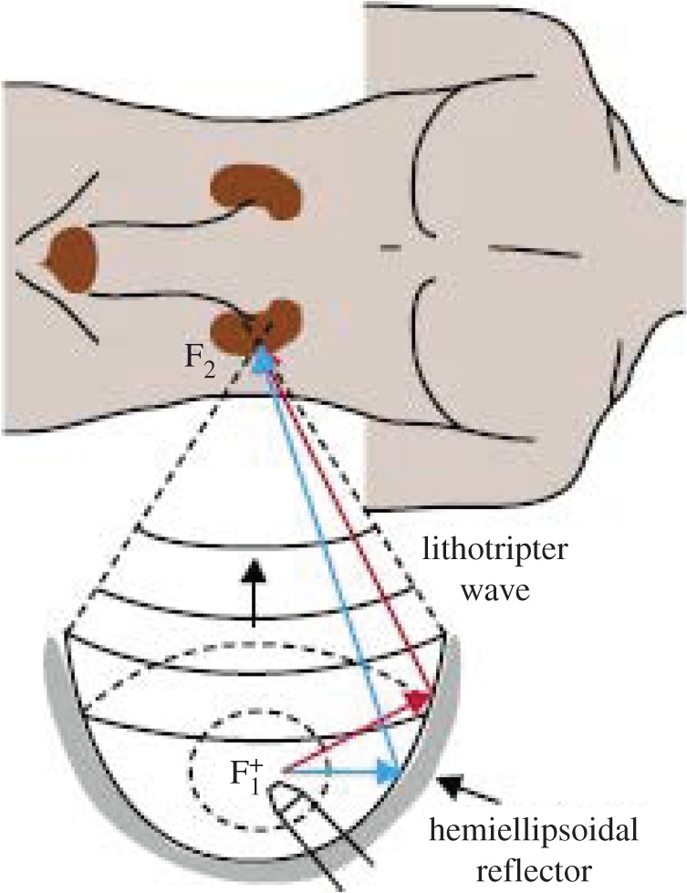
Schematic of lithotripter or HIFU therapy. (Online version in colour.)
Modest amplitudes in the focal region are commonly used to produce heating while avoiding cavitation. For example, this is used for haemostasis, to stop bleeding in internal organs [35] such as the liver [36] or spleen [37]. It can also be used for tumour necrosis [17], thermally ablating tumours in a minimally invasive fashion. Ultrasound has also been used to help break up blood clots in a therapy known as sonothrombolysis [29,38,39]. In most of these treatments, the amplitudes are designed to be small enough to avoid cavitation which could cause too much collateral damage. However, we will focus here primarily on those strategies that involve more powerful waves that produce and use cavitation.
4.4. Focused ultrasound in lithotripsy
The use of larger amplitude HIFU to produce cavitation in order to break solid objects in the target area, for example to fission kidney or gall stones, is now widespread. The cavitation generated at the focal point (figure 19) pulverizes the material of the stone, ultimately reducing it to a powder [13]. This is very similar to shockwave lithotripsy (see below) but instead uses HIFU. The use of HIFU in lithotripsy is relatively recent [38] and has some significant advantages. With a significantly narrower spectrum HIFU can be focused much more precisely. It is therefore possible to limit the region of cavitation more narrowly on the surface of the stone, enhancing the damage to the stone while reducing the collateral damage.
Figure 19.

Bubble cloud (centre) on the face of a target stone (right; adapted from [11], reproduced with permission).
5. Lithotripsy, focused shockwaves
Lithotripsy [38,40,41] is the therapy that focuses shockwaves at a target site within the body in order to remotely disintegrate kidney and gall stones. With the patient submerged in a water bath (so that the surroundings closely match the acoustic impedance of the body), shockwaves are focused at the site of the stone and multiple shocks are then administered in order to break the stone into pieces small enough to be ejected by the body. Cavitation may or may not play a role in the disintegration of the stone; it can also cause substantial collateral tissue damage. For an excellent review of lithotripsy research, the reader is referred to Bailey et al. [38].
Lithotripsy using shockwaves has a long history [42]. Figure 20 exemplifies the fracture of an artificial stone by lithotripsy using strong shockwaves. It seems likely that this form of comminution results from shock-induced stresses rather from than cavitation. On the other hand, the damage shown in figure 21 seems to be quite characteristic of cavitation. Frequency dispersion prevents the shockwaves from being more narrowly focused and consequently the focal volume is often significantly larger than the target stone. Figure 22 shows the formation of cavitation bubbles on an artificial stone in a shockwave lithotripter. Another illustration, figure 23, exemplifies how widespread the cavitation can be in a focal volume significantly larger than the target stone (the larger black object on the right). Consequently, the cavitation generated by the shockwaves causes substantial collateral tissue damage in conventional lithotripsy. Double pulse shockwave lithotripsy can help reduce this focal volume [13].
Figure 20.

Artificial stone fractured by shockwave lithotripsy (adapted from [43], reproduced with permission).
Figure 21.

Artificial renal stone exhibiting damage (courtesy of E. Hatt and J.C. Williams, Indiana University).
Figure 22.

Cavitation bubbles near the surface of an artificial stone (courtesy of D. Sokolov, M.R. Bailey, University of Washington).
Figure 23.

Typical shockwave lithotripsy bubble cloud near a stone (larger black object) (adapted from [44], reproduced with permission).
Various techniques have been investigated in order to try to refine lithotripter design. These usually have the competing objectives of limiting the collateral damage by confining the cavitation to a well-defined region while at the same time generating the most damage potential. These are partially competing objectives and the strength of the shockwaves (or ultrasound) is usually limited by the need to minimize collateral damage. However, knowledge of the intricacies of bubble dynamics suggests some superior strategies. Thus, for example, in shockwave lithotripsy multiple pulses [19] may be better than single pulses.
As another example, we would note the strategy devised by Matsumoto et al. [11], who found that a period of high-frequency ultrasound followed by a few low-frequency cycles can be very effective. The high-frequency period generates a cloud of small bubbles in the focal region by the process of rectified diffusion [2]. The subsequent low-frequency pulses then cause the collapse of this cloud in the manner described by Wang & Brennen [6,7].
6. Laser-induced cavitation
Another method of generating cavitation in a selected region is by means of a focused laser beam. Known as photodisruption, the focused laser light creates cavitation bubbles that cut through tissue and thus generate precise microscopic incisions that are of great potential value in many surgical procedures. Known as light scalpels, Nd:YAG laser pulses have, for example, become a well-established tool in non-invasive intraocular surgery [45–49].
The key to these tools is to produce repetitive, low energy pulses that have a very small damage range and thus limit undesirable collateral damage. As Vogel and his co-workers have demonstrated [48,49], the extent of the damage is proportional to the cube root of the pulse energy, and therefore, the objective is to use the lowest energy laser pulse that still causes cavitation. Vogel et al. [49] have shown that this can be achieved by reducing the duration of the laser pulses and that picosecond pulses are therefore superior to nanosecond pulses. Some of their photographs are reproduced in figure 24; each frame shows the extent of both the shockwave associated with the initiation of cavitation and, inside that, the cavitation bubble itself. The laser pulse is arriving from the right and the shape is of the images is, in part, determined by the shape of the focal volume.
Figure 24.

Shockwaves and bubbles formed at the focal point by picosecond laser pulses (a,b) and by nanosecond pulses (c,d). Beam coming from right (adapted from [49], reproduced with permission).
Focused laser light is also used in other surgical procedures, for example, laser-induced lithotripsy [50] and in neurosurgery. In the latter, the primary issue is a concern for the limited control of the real-time laser interactions with the neural tissue [51]. Another example of laser-induced cavitation is the procedure known as percutaneous laser disc decompression [52]. Laser energy is introduced into the nucleus pulposus (the gelatinous core of a spinal disc) through a needle in order to vaporize a small volume of the nucleus and, by removing that volume, reducing the pressure of the disc and thus relieving the pressure on the neural tissue.
7. Manipulation of cavitation nuclei
7.1. Target nuclei and special nuclei
The nucleation sites that initiate cavitation represent a key feature in any cavitation phenomenon. Consequently, in recent years, there have been significant potential advances in therapies that involve the introduction into the target region of nuclei that will promote and/or control cavitation. For example in HIFU therapies, the controlled and confined introduction of nuclei to the target region prior to the HIFU bombardment can lead to more tightly controlled treatments and reduced collateral damage.
Most evident in this emerging new aspect of the use of cavitation in medicine is the deployment of liposomes or injected microbubbles in conjunction with focused ultrasound (figure 25). A liposome is a very small spherical structure (up to 10 µm is size) formed from the same material as a cell membrane. As illustrated in figure 26, they can be manufactured with a variety of contents, structures and appendages in order to carry drugs to desired sites, to preferentially attach to desired cells or sites or to include a gaseous interior so that they respond (explode) when bombarded with ultrasound. This technology (for a comprehensive review, see Ibsen et al. [53]) has created a whole new spectrum of possible therapies in which liposomes or special microbubbles (figure 27) are devised to transport drugs to specific sites where ultrasound is then used to deposit the drug at its intended target in a procedure known as sonoporation [28].
Figure 25.

Schematic of cancer treatment with liposomes and ultrasound (adapted from [53], reproduced with permission). (Online version in colour.)
Figure 26.

Some of the various designs of special purpose liposomes (adapted from [53], reproduced with permission). (Online version in colour.)
Figure 27.

Example of a liposome or microbubble constructed for drug delivery by sonoporation (adapted from [28], reproduced with permission). (Online version in colour.)
A wide spectrum of special purpose liposomes have been designed and an idea of the variety can be gauged from the selection shown in figure 26. In the example shown in figure 27, gas-filled microbubbles have been designed with drug- and gas-loaded interiors. A stabilizing coating surrounds the bubble which may be targeted to specific tissue by incorporating protein ligands on the surface. Drugs can be incorporated by themselves or, if insoluble in water, in an oil layer. Perhaps the most exciting of these therapies is the possibility of the delivery of genetic material to a chosen site [28,54,55] as illustrated in figure 28. Focused ultrasound is then used to cavitate the gene-loaded microbubble and the shockwaves or microjets thus generated cause the genetic material to be injected into the surrounding cells. Even more remarkable are the recent efforts to manipulate individual microbubbles using optical trapping [56] or by embedding magnetic particles in the liposome so as to move them electromagnetically [57]. The liposomes or microbubbles can then be placed in an optimal location next to the targeted cell or tissue, even to the extent of injecting new DNA without destroying the target cell [56].
Figure 28.

Gene delivery using ultrasound and microbubbles (adapted from [28], reproduced with permission). (Online version in colour.)
7.2. Nuclei control
Moreover, it is of value to consider ways in which the nuclei population might be controlled so as to modify the cavitation characteristics of a procedure or a device. The author was recently involved with a project in which bubble nucleation suppression was remarkably successful [58,59]. The context is a system designed to inject a highly supersaturated aqueous solution of oxygen into the bloodstream in order to minimize tissue damage caused by oxygen deprivation in the aftermath of a heart attack or stroke. The aqueous solution of oxygen is prepared at very high pressure (hundreds of atmospheres) and then is injected through very small capillaries (hundreds of micrometres) at high speed (m s−1). The trick is to accomplish mixing with the receiving fluid without nucleation, that is, without the formation of gaseous oxygen bubbles; this was achieved as follows.
Because of the high-speed and high-pressure gradient within the capillary, only a short length close to the exit has a pressure below the saturation level. Consequently, only nucleation sites within this short length have the potential to produce bubbles. Observations [58,59] showed that there were typically only of the order of 10 such sites in the drawn silica capillaries. Moreover, these sites could be deactivated by the simple expedient of flushing ethanol through the capillary while it was underwater. Apparently, the ethanol preferentially wets the interior surface of the site and removes the buried nucleation bubble. The ethanol may also help dissolve the gas in the nuclei, because the solubility in ethanol is about an order of magnitude larger than the solubility in water. This process of ethanolization of the surface was remarkably successful in suppressing nucleation. Moreover, it was made compatible with medical injection by preparing the capillary with an interior coating of benzalkonium heparin laid down in ethanol. This remarkably successful example of nucleation control suggests that similar strategies might be successfully employed in other contexts.
8. Final comments
Perhaps the most challenging feature of all the emerging therapies is the need to control or manage cavitation. It seems clear that the desirability of such control is almost universal. The dual motivations are an increase in the effectiveness of the procedure and a reduction in the collateral damage. However, the methods devised for this control vary greatly. In phacoemulsification, spatial control is sought through the design of the ultrasonic probe and the deployment of additional features such as rotation. In other circumstances, temporal rather than spatial control is attempted. Thus, in lithotripsy, multiple pulses are used, and more sophisticated sequencing strategies are being investigated. A different temporal control approach is embodied in the picosecond laser pulses of Vogel and his co-workers.
Perhaps most exciting are the possible inventions and uses of special nuclei, liposomes and microbubbles, devised to attack individual tissues and cells. The horizons seem limitless and the explosion in the designs of liposomes will, no doubt, lead to extraordinary new therapies. In perusing this new literature, it strikes this author that, though new liposome structures are emerging with great rapidity, the potential for the manipulation of liposomes using the physical responses to ultrasound (for example microstreaming, Bjerknes' forces or rectified diffusion) has yet to be realized.
Nevertheless, there can be little doubt that, in the future, the benefits of cavitation will far outweigh the detrimental effects.
Acknowledgements
Many individuals provided me with valuable assistance in the preparation of this review, including Tim Colonius, Allan Acosta, Yoichiro Matsumoto, Aziz Anis, Michel Tanguay, Brant Maines, Morteza Gharib, Larry Crum, Tim Baldwin and Eric Johnsen.
Competing interests
I declare I have no competing interests.
Funding
I received no funding for this study.
References
- 1.Rayleigh L. 1917. One the pressure developed in a liquid during the collapse of a spherical cavity. Phil. Mag. Ser. 6, 34, 94–98. ( 10.1080/14786440808635681) [DOI] [Google Scholar]
- 2.Brennen CE. 1995. Cavitation and bubble dynamics. Oxford, UK: Oxford University Press; Reprinted by Cambridge University Press. [Google Scholar]
- 3.Kuhn de Chizelle Y, Ceccio SL, Brennen CE. 1995. Observations and scaling of travelling bubble cavitation. J. Fluid Mech. 293, 99–126. ( 10.1017/S0022112095001650) [DOI] [Google Scholar]
- 4.Benjamin TB, Ellis AT. 1966. The collapse of cavitation bubbles and the pressures thereby produced against solid boundaries. Phil. Trans. R. Soc. Lond. A 260, 221–240. ( 10.1098/rsta.1966.0046) [DOI] [Google Scholar]
- 5.Frost D, Sturtevant B. 1986. Effects of ambient pressure on the instability of a liquid boiling explosively at the superheat limit. ASME J. Heat Transf. 108, 418–424. ( 10.1115/1.3246940) [DOI] [Google Scholar]
- 6.Wang Y-C, Brennen CE. 1994. Shock wave development in the collapse of a cloud of bubbles. ASME Cavitation Multiphase Flow Forum FED-194, 15–20. [Google Scholar]
- 7.Wang Y-C, Brennen CE. 1999. Numerical computation of shock waves in a spherical cloud of cavitation bubbles. ASME J. Fluids Eng. 121, 872–880. ( 10.1115/1.2823549) [DOI] [Google Scholar]
- 8.Soyama H, Kato H, Oba R. 1992. Cavitation observations of severely erosive vortex cavitation arising in a centrifugal pump. In Proc. 3rd IMechE Int. Conf. on Cavitation, Cambridge, UK, 9–11 December 1992, pp. 103–110.
- 9.Bark G, van Berlekom WB. 1978. Experimental investigations of cavitation noise. In Proc. 12th ONR Symp. on Naval Hydrodynamics, Washington, DC, 5–9 June 1978, pp. 470–493.
- 10.Reisman GE, Wang Y-C, Brennen CE. 1998. Observations of shock waves in cloud cavitation. J. Fluid Mech. 355, 255–283. ( 10.1017/S0022112097007830) [DOI] [Google Scholar]
- 11.Matsumoto Y, Allen J, Yoshizawa S, Ikeda T, Kaneko Y. 2003. Renal stone communition utilizing cavitation erosion. In Proc. 3rd Int. Symp. on Therapeutic Ultrasound, Lyon, France, 22–25 June 2003, pp. 49–54. [Google Scholar]
- 12.Tanguay M, Colonius T.2002. Numerical investigation of bubble cloud dynamics in shock wave lithotripsy. In Proc. ASME Joint US–European Fluids Engineering Division Conf., Montreal, Canada, 14–18 July 2002 , pp. 389–394. ( ) [DOI]
- 13.Sokolov DL, Bailey MR, Crum LA. 2001. Use of a dual-pulse lithotripter to generate a localized and intensified cavitation field. J. Acoust. Soc. Am. 110, 1685–1695. ( 10.1121/1.1394221) [DOI] [PubMed] [Google Scholar]
- 14.Paterson RF, Lifshitz DA, Lingeman AP, Evan BA, Connors JC, Williams JC Jr, McAteer JA. 2002. Stone fragmentation during shock wave lithotripsy is improved by slowing the shock wave rate: studies with a new animal model. J. Urol. 168, 2211–2215. ( 10.1016/S0022-5347(05)64357-1) [DOI] [PubMed] [Google Scholar]
- 15.Stinebring DR, Lamson TC, Deutsch S. 1991. Techniques for in vitro observation of cavitation in prosthetic heart valves. ASME Cavitation and Multiphase Flow FED-109, 119–124. [Google Scholar]
- 16.Lamson TC, Rosenberg G, Geselowitz DB, Deutsch S, Stinebring DR, Frangos JA, Tarbell JM. 1993. Relative blood damage in the three phases of a prosthetic heart valve flow cycle. ASAIO J. 39, M626–M633. ( 10.1097/00002480-199339030-00091) [DOI] [PubMed] [Google Scholar]
- 17.Garrison LA, Lamson TC, Deutsch S, Geselowitz DB, Gaumond RP, Tarbell JM. 1994. An in vitro investigation of prosthetic heart valve cavitation in blood. J. Heart Valve Dis. 3(Suppl 1), S8–S24. [PubMed] [Google Scholar]
- 18.Stinebring DR, Deutsch S, Sneckenberger DS, Zapanta C, Tarbell JM. 1995. Investigations of cavitation in prosthetic heart valves. ASME Cavitation and Multiphase Flow FED-210, 95–103. [Google Scholar]
- 19.Zapanta CM, et al. 1996. In vivo observation of cavitation in prosthetic heart valves. ASIAO J. 42, M550–M554. ( 10.1097/00002480-199609000-00047) [DOI] [PubMed] [Google Scholar]
- 20.Zapanta CM, Stinebring DR, Deutsch S, Geselowitz DB, Tarbell JM. 1998. A comparison of the cavitation potential of prosthetic heart valves based on valve closing dynamics. J. Heart Valve Dis. 7, 655–667. [PubMed] [Google Scholar]
- 21.Rambod E, Beizaie M, Shusser M, Milo S, Gharib M. 1999. A physical model describing the mechanism for formation of gas microbubbles in patients with mitral mechanical heart valves. Ann. Biomed. Eng. 27, 774–792. ( 10.1114/1.231) [DOI] [PubMed] [Google Scholar]
- 22.Maines BH, Brennen CE. 2002. Applicability of fluid transient test methods for mechanical heart valve cavitation scaling. 6th Annual Hilton Head Workshop on Prosthetic Heart Valves: Past, Present and Future, Hilton Head Island, SC, 6–10 March 2002. [Google Scholar]
- 23.Brennen CE. 1995. Hydrodynamics of pumps. Cambridge, UK: Cambridge University Press. [Google Scholar]
- 24.Goldsmith W. 2001. The state of head injury biomechanics: past, present and future: part 1. Crit. Rev. Biomed. Eng. 29, 441–600. ( 10.1615/CritRevBiomedEng.v29.i56.10) [DOI] [PubMed] [Google Scholar]
- 25.Goldsmith W. 1972. Biomechanics of head injury. In Biomechanics, its foundations and objectives (eds Fung YC, Perrone N, Anliker M), pp. 585–634. New York, NJ: Prentice Hall. [Google Scholar]
- 26.Lubock P, Goldsmith W. 1980. Experimental cavitation studies in a model head–neck system. J. Biomech. 13, 1041–1052. ( 10.1016/0021-9290(80)90048-2) [DOI] [PubMed] [Google Scholar]
- 27.Young PG, Morfey CL. 1998. Intracranial pressure transients caused by head impacts. Proc. IRCOBI 26, 391–403. [Google Scholar]
- 28.Blomley MJK, Cooke JC, Cosgrove DO. 2001. Microbubble contrast agents: a new era in ultrasound. Br. Med. J. 322, 1222–1225. ( 10.1136/bmj.322.7296.1222) [DOI] [PMC free article] [PubMed] [Google Scholar]
- 29.Crum LA, Bailey MR, Hwang JH, Khohlova V, Sapozhnikov O. 2009. Therapeutic ultrasound: recent trends ad future perspectives. Phys. Proc. 3, 25–34. ( 10.1016/j.phpro.2010.01.005) [DOI] [Google Scholar]
- 30.Williams AR. 1983. Ultrasound: biological effects and potential hazards. San Diego, CA: Academic Press. [Google Scholar]
- 31.Kelman CD. 1967. Phaco-emulsification and aspiration; a new technique of cataract removal; a preliminary report. Am. J. Ophthalmol. 64, 23–35. ( 10.1016/0002-9394(67)93340-5) [DOI] [PubMed] [Google Scholar]
- 32.FDA CDRH. 1996. FDA Center for Devices and Radiological Health. Office of Science and Technology Annual Report. Section 18. http://www.fda.gov/cdrh/ost/index.html.
- 33.Anis AY. 1999. PhacoTmesis. In Atlas of cataract surgery (eds Masket S, Crandall AS), pp. 89–96. London, UK: Martin Dunitz. [Google Scholar]
- 34.Ceccio SL, Brennen CE. 1991. Observations of the dynamics and acoustics of travelling bubble cavitation. J. Fluid Mech. 233, 633–660. ( 10.1017/S0022112091000630) [DOI] [Google Scholar]
- 35.Vaezy S, Martin R, Mourad P, Crum LA. 1999. Hemostasis using high intensity focused ultrasound. Eur. J. Ultrasound 9, 79–87. ( 10.1016/S0929-8266(99)00014-2) [DOI] [PubMed] [Google Scholar]
- 36.Vaezy S, et al. 1997. Liver hemostasis using high intensity focused ultrasound. Ultrasound Med. Biol. 23, 1413–1420. ( 10.1016/S0301-5629(97)00143-9) [DOI] [PubMed] [Google Scholar]
- 37.Vaezy S, et al. 1999. Control of splenic bleeding using high intensity ultrasound. J. Trauma 47, 521–525. ( 10.1097/00005373-199909000-00015) [DOI] [PubMed] [Google Scholar]
- 38.Bailey MR, Khokhlova VA, Sapozhnikov OA, Kargl SG, Crum LA. 2003. Physical mechanisms of the therapeutic effect of ultrasound (a review). Acoust. Phys. 49, 437–464. ( 10.1134/1.1591291) [DOI] [Google Scholar]
- 39.Alexandrov AV, Demchuk AM, Felberg RA, Christou I, Barber PA, Burgin WS, Malkoff M, Wojner AW, Grotta JC. 2000. High rate of complete recanalization and dramatic clinical recovery during tPA infusion when continuously monitored with 2-MHz transcranial Doppler monitoring. Stroke 31, 610–615. ( 10.1161/01.STR.31.3.610) [DOI] [PubMed] [Google Scholar]
- 40.Coleman AJ, Saunders JE, Crum LA, Dyson M. 1987. Acoustic cavitation generated by an extra corporeal shockwave lithotripter. Ultrasound Med. Biol. 13, 69–76. ( 10.1016/0301-5629(87)90076-7) [DOI] [PubMed] [Google Scholar]
- 41.Chaussy C, Brendel W, Schmiedt E. 1980. Extracorporeally induced destruction of kidney stones by shock waves. Lancet 316, 1265–1268. ( 10.1016/S0140-6736(80)92335-1) [DOI] [PubMed] [Google Scholar]
- 42.Sturtevant B. 1996. Shock wave physics of lithotripters. In Smith's textbook of endourology, pp. 529–552. St. Louis, MO: Quality Medical. [Google Scholar]
- 43.Eisenmenger W. 2001. The mechanisms of stone fragmentation in ESWL. Ultrasound Med. Biol. 27, 683–693. ( 10.1016/S0301-5629(01)00345-3) [DOI] [PubMed] [Google Scholar]
- 44.Zhu S, Cocks FH, Preminger GM, Zhong P. 2002. The role of stress waves and cavitation in stone comminution in shock wave lithotripsy. Ultrasound Med. Biol. 28, 661–671. ( 10.1016/S0301-5629(02)00506-9) [DOI] [PubMed] [Google Scholar]
- 45.Fankhauser F, Rousel P, Steffen J, Van der Zypen E, Chrenkova A. 1981. Clinical studies on the efficiency of high power laser radiation upon some structures of the anterior segment of the eye. Int. Opthalmol. 3, 129–139. ( 10.1007/BF00130696) [DOI] [PubMed] [Google Scholar]
- 46.Aron-Rosa D, Aron JJ, Griesemann M, Thyzel R. 1980. Use of the Nd:YAG laser to open the posterior capsule after lens implant surgery: a preliminary report. Am. Intraocul. Implant Soc. J. 6, 352–354. ( 10.1016/S0146-2776(80)80036-X) [DOI] [PubMed] [Google Scholar]
- 47.Steinert RF, Puliafito CA. 1985. The Nd:YAG laser in ophthalmology. Philadelphia, PA: Saunders. [Google Scholar]
- 48.Vogel A, Lauterborn W, Timm R. 1989. Optical and acoustical investigations of the dynamics of laser-produced cavitation bubbles near a solid boundary. J. Fluid Mech. 206, 299–338. ( 10.1017/S0022112089002314) [DOI] [Google Scholar]
- 49.Vogel A, Busch S, Parlitz U. 1996. Shock wave emission and cavitation bubble generation by picosecond and nanosecond optical breakdown in water. J. Acoust. Soc. Am. 100, 148–165. ( 10.1121/1.415878) [DOI] [Google Scholar]
- 50.Steiner R (ed.). 1988. Laser lithotripsy: clinical use and technical aspects. Berlin, Germany: Springer; ( 10.1007/978-3-642-73864-7) [DOI] [Google Scholar]
- 51.Krishnamurthy S, Powers SK. 1994. Lasers in neurosurgery. Lasers Surg. Med. 15, 126–167. ( 10.1002/lsm.1900150203) [DOI] [PubMed] [Google Scholar]
- 52.Choy DSJ. 1998. Percutaneous laser disc decompression (PLDD): twelve years’ experience with 752 procedures in 518 patients. J. Clin. Laser Med. Surg. 16, 325–331. [DOI] [PubMed] [Google Scholar]
- 53.Ibsen S, Schutt CE, Esener S. 2013. Microbubble-mediated ultrasound therapy: a review of its potential in cancer treatment. Drug Des. Dev. Ther. 7, 375–388. ( 10.2147/DDDT.S31564) [DOI] [PMC free article] [PubMed] [Google Scholar]
- 54.Price RJ, Skyba DM, Kaul S, Skalak TC. 1998. Delivery of colloidal particles and red blood cells to tissue through microvessel ruptures created by targeted microbubble destruction with ultrasound. Circulation 98, 1264–1267. ( 10.1161/01.CIR.98.13.1264) [DOI] [PubMed] [Google Scholar]
- 55.Taniyama Y, et al. 2002. Development of safe and efficient novel nonviral gene transfer using ultrasound: enhancement of transfection efficiency of naked plasmid DNA in skeletal muscle. Gene Ther. 9, 372–380. ( 10.1038/sj.gt.3301678) [DOI] [PubMed] [Google Scholar]
- 56.Prentice PA, Cuschieri A, Dholakia K, Prausnitz MR, Campbell PA. 2005. Membrane disruption by optically controlled microbubble cavitation. Nat. Phys. 1, 107–110. ( 10.1038/nphys148) [DOI] [Google Scholar]
- 57.Stride E, Porter C, Prieto AG, Pankhurst Q. 2009. Enhancement of microbubble mediated gene delivery by simultaneous exposure to ultrasonic and magnetic fields. Ultrasound Med. Biol. 35, 861–868. ( 10.1016/j.ultrasmedbio.2008.11.010) [DOI] [PubMed] [Google Scholar]
- 58.Brennen CE. 2002. Micro-nucleation in supersaturated oxygen solution injection. In Proc. JSME Mechanical Engineering Congress, Tokyo, Japan, 24–28 September 2002, pp. 18–19. [Google Scholar]
- 59.Creech J, Divino V, Patterson W, Zalesky PJ, Brennen CE. 2002. Injection of highly supersaturated oxygen solutions without nucleation. ASME J. Biomed. Eng. 124, 676–683. ( 10.1115/1.1519558) [DOI] [PubMed] [Google Scholar]