Abstract
Polyamidoamine (PAMAM) dendrimers have emerged as an important class of nanostructured materials and have found a broad range of applications. There is also an ongoing effort to synthesize higher-complexity structures using PAMAM dendrimers as enabling building blocks. Herein, we report for the first time the fabrication of electrospun nanocomposite fibers composed of dendrimer derivatives, namely PEGylated PAMAM dendrimers, blended with a small amount of high-molecular-weight polyethylene oxide (PEO). Morphological features and mechanical properties of the resulting dendrimer fiber mats were assessed.
Keywords: electrospinning, dendrimer, nanofiber, PEGylation, fast Fourier transform
Graphical Abstract
1. Introduction
Polyamidoamine (PAMAM) dendrimers have emerged as an important class of nanostructured materials and have found a broad range of applications by virtue of their highly branched, nearly perfect monodisperse structures of varying sizes. These distinct nanodomain features include a hydrophobic interior and a relatively hydrophilic surface presenting numerous functional groups [1, 2]. The structural versatility of PAMAM dendrimers has led to a vast array of intriguing dendritic architectures as nanocarriers for therapeutic and diagnostic applications [3, 4]. There is also an ongoing effort to synthesize higher-complexity structures using PAMAM dendrimers as enabling building blocks [5–7]. Of particular interest is the utility of PAMAM dendrimers in construction of high-dimensional structures for drug delivery and tissue engineering applications [8]. For instance, PAMAM dendrimers are used as a cross-linker [9] or building block [10] to construct cross-linked networks.
Electrospinning has been widely adopted to make fibers with desirable structural features for drug delivery and tissue engineering application [11–17]. A wide range of synthetic and natural linear polymers have been electrospun into fibers with success [18]. Although polymer molecular weight and solution concentration are critical in successful electrospinning, intermolecular chain entanglements within the polymer are very important to stable fiber formation as well [18]. Probably because of the widely recognized steric crowding on the dendrimer periphery precluding chain entanglements, there is scarcity in the literature on the fabricating of dendrimer fibers via electrospinning. Madani et al. reported electrospinning of blends of nonfunctionalized PAMAM dendrimers and high-molecular-weight polyethylene oxide (PEO), in which PEO, however, accounts for a large proportion (at least 30% by weight) of fiber mass [19]. Our recent work shows that PAMAM dendrimer can be hybridized with linear polymers, e.g., gelatin, and electrospun into fibers as a secondary component [20]. Alternatively, PAMAM dendrimers can be covalently coupled to fibers in a post-electrospinning step [21].
In this work, we report for the first time electrospun we report for the first time the fabrication of electrospun nanocomposite fibers composed of dendrimer derivatives, namely PEGylated PAMAM dendrimers, blended with a small amount of high-molecular-weight polyethylene oxide (PEO). The new dendrimer-containing nanocomposite fibers represent a new structure with added complexity of dendrimer and fibrous mat. PEGylation of dendrimers also reduces the cytotoxicity of the resulting conjugate of the nanomaterial due to the superb biocompatibility of PEG [22–24]. PEGylated dendrimers also encourage greater retention time in the circulatory system due to the stealth properties of PEG [25]. We envision that new dendrimer-containing fibers will broaden the use of dendrimers in biomedical applications such as drug delivery, and the ease of fabrication via electrospinning will allow this new platform to be readily translatable.
2. Experimental section
2.1. Synthesis of PEGylated PAMAM dendrimer conjugates
PAMAM dendrimer G3.0 was used as the underlying core for the synthesis because of its combination of possessing low cytotoxicity at high molar concentrations and a relatively large number of surface groups for functionalization [22–24]. Methoxypolythylene glycol (mPEG, 2000 g/mol) was coupled to PAMAM dendrimer G3.0 at feed molar ratios of 32:1 and 16:1, respectively following the method published by us [26]. These two molar ratios were chosen to ensure the resulting PEGylated dendrimer conjugates with discrete degrees of PEGylation could be achieved [26]. PEGylated G3.0 conjugates were purified using SnakeSkin tubing with 7000 MWCO and freeze dried.
2.2. Electrospinning
Electrospinning solutions of mPEG or mPEG-G3.0 with or without high-molecular-weight PEO additive were prepared in 1,1,1,3,3,3-hexafluoro-2-propanol (HFP) and tested for fiber formation (Table 1). The electrospinning solution was then drawn up through a blunt-end needle (18G×1½ in) on a 5 ml syringe. The syringe was loaded into a syringe pump, delivering the solution to the needle orifice 30 cm away from the collecting mandrel at a rate of 2 ml/h. The needle and the collection target were connected to a positive electrode (+ 20 kV) and the earth ground of a high voltage power supply (Spellman CZE100R, Spellman High Voltage Electronics Corporation), respectively. Fibers were collected on a rounded, stainless steel mandrel (120 mm length with 6 mm diameter) rotating at 500 rpm.
Table 1.
Electrospinning conditions tested for fiber formation.
| Polymer (A/B) | A (% w/v) | B (% w/v) | Fiber formation |
|---|---|---|---|
| mPEG2000/PEO | 20–25 | 0 | No |
| mPEG2000/PEO | 20–25 | 0.05–0.1 | Yes |
| mPEG-G3.0 (32:1)/PEO | 20–40 | 0 | No |
| mPEG-G3.0 (32:1)/PEO | 15 | 1 | Yes |
| mPEG-G3.0 (16:1)/PEO | 15 | 1 | Yes |
2.3. 1H NMR spectroscopy
1H NMR spectra were recorded on a Varian Mercury 600 MHz spectrometer. Deuterium oxide (D2O, 99.9%) was used as solvent in 1H NMR measurements. 1H NMR spectroscopy was applied to characterize PEGylated G3.0 conjugates and determine actual degrees of PEGylation.
2.4. Scanning electron microscopy (SEM)
Prior to SEM imaging, scaffolds were placed on a 1 cm diameter stub. The stub was placed on a specimen holder and gold sputter coated. SEM images were taken on a JEOL JSM-5610LV scanning electron microscope. One hundred randomly chosen fibers in each SEM image were analyzed with UTHSCSA ImageTool™ software for fiber diameter and pore size measurements.
2.5. Tensile testing
“Dog-bone” shaped samples (n=8) were obtained using a punch die (ODC Testing & Molds) of the dimensions 19.0, 3.2 and 6.1 mm at its length, narrowest point and widest point, respectively. Mechanical properties of the samples, including peak load, peak stress, modulus, strain at break and energy to break, were tested using the MTS Bionix 200 Mechanical Testing System in conjunction with TestWorks 4.0 software.
2.6. Fast fourier transform (FFT)
FFT technique was conducted to analyze the degree of fiber alignment and anisotropy based on the work reported by Ayers and coworkers [27]. This was completed by taking the SEM image of the scaffolds and converting its image information from the time domain to a discrete frequency domain [27]. The output image after FFT is grayscale pixels within a circle that have varying intensities with respect to its angle about the circle’s central point. Image conversion and analysis was done on Image J software.
2.7. Statistical analysis
Statistical analysis was completed using unpaired t-test and the Mann-Whitney method for subgroup comparison. A p-value less than 0.05 was considered statistically significant.
3. Results and Discussion
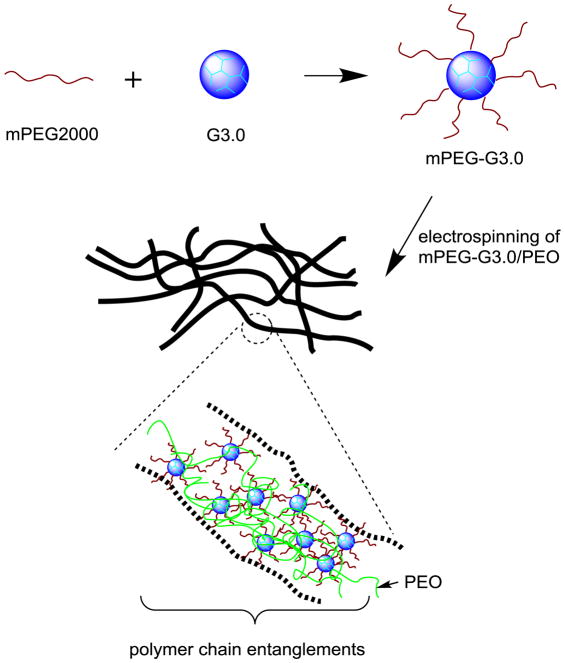
For the demonstration of proof-of-concept, we chose amine-terminated PAMAM dendrimer G3.0 as the underlying core (Scheme 1). We coupled mPEG2000 to the dendrimer surface at feed molar ratios of 16:1 and 32:1, respectively, following a procedure previously described [26]. According to 1H NMR spectroscopy characterization (Figure 1), the degrees of PEGylation of mPEG-G3.0 (16:1) and mPEG-G3.0 (32:1), i.e., percentages of dendrimer PEG surface amines coupled to PEG were 44% and 92%, respectively. For electrospinning fabrication, coupling mPEG to PAMAM dendrimer G3.0 at 32:1 (i.e. 100% PEGylation) would be more favorable. However, for drug delivery applications, an increased density of mPEG chains can reduce the ability to couple drugs and moieties of interest due to steric hindrance of PEG and reduced surface groups [26].
Scheme 1.
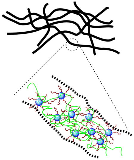
Schematic illustration of synthesis and electrospinning of mPEG-G3.0 blended with a small amount of high-molecular-weight PEO 900,000 Da.
Figure 1.
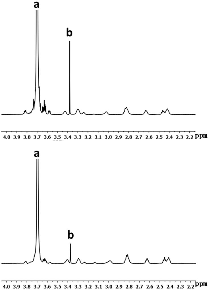
1H NMR spectrum of PEGylated PAMAM dendrimers. (A) mPEG-G3.0 (32:1) and (B) mPEG-G3.0 (16:1). (peak a, –(CH2CH2O)n–; peak b, CH3–CH2–CH2–O–; multiple peaks 2.4–3.45 ppm, methylene protons of dendrimer)
It is challenging to make fibers out of pure dendrimers or PEGylated dendrimers because of their highly compact structures, low chain entanglements, and high viscosity. Although it remains controversial as to whether the presence of chain entanglements is essential for fiber formation, it has been shown that a small fraction of PEO in electrospinning solution promotes PEG fiber formation, which was attributed to fluid elasticity increase by PEO other than chain entanglements [28]. Electrospinning solutions of mPEG or mPEG-G3.0 with or without high-molecular-weight PEO additive were tested for electrospinning. After mPEG-G3.0 (16:1 and 32:1) (15% w/v in HFP) was blended with PEO (Mv=900,000 Da) (1% w/v), mPEG-G3.0 was successfully electrospun into fiber mats, presumably as a result of promotion of both chain entanglements and fluid elasticity. Fluid elasticity of mPEG-G3.0 solution was attributed to its ability to adjust to stresses during a longer period of relaxation time [28]. Quantitative analysis of rheological properties of mPEG-G3.0 electrospinning solutions is warranted for electrospinning optimization and will be investigated in future work.
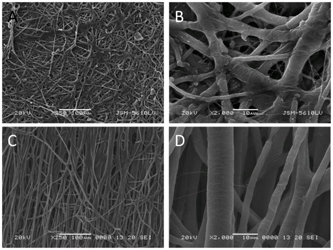
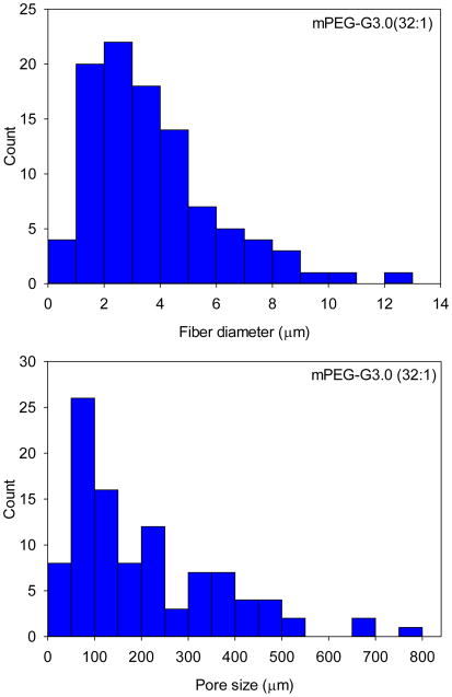
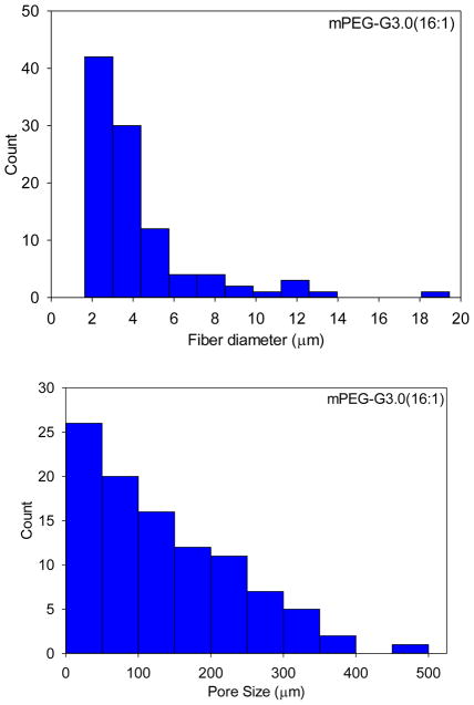
SEM images obtained on a JEOL JSM-5610LV scanning electron microscope were used to characterize the electrospun mat’s fiber morphology. As shown in Figure 2, mPEG-G3.0 (32:1) fibers exhibited some beads. The beading formation could be due to applied charges breaking the solution up into droplets, otherwise known as Rayleigh instability. According to the histograms of fiber size and pore size distributions shown in Figure 3, the average diameters of mPEG-G3.0 (32:1) and mPEG-G3.0 (16:1) fibers were 3.8±2.3 μm and 4.2±2.8 μm, respectively. These relatively large variations in fiber diameter are presumably attributed to high polymer solutions (10% or higher), which have a tendency to produce a non-normally distributed population of fibers [29]. Average pore sizes of mPEG-G3.0 (32:1) and mPEG-G3.0 (16:1) fiber mats were 209 μm2 and 135 μm2, respectively. Typically, electrospun scaffolds exhibit fiber diameters in the micrometer diameter range with the capability to achieve the nanometer fiber diameters under proper processing conditions. For this study, these scaffolds were in the micron range. This is likely due to the high concentration of mPEG-G3.0 (Table 1) in electrospinning solution. One potential method to create fibers in the nanoscale would be to 1) reduce the mPEG-G3.0 concentration below 10% to create nanofibers as illustrated for PEO in literature and 2) increase the PEO additive concentration from 1% (Table 1) up to 7% to improve spinnability [29]. The balance of those two parameters could help achieve stable, nano-scaled fibers that can closely mimic the extracellular matrix, encouraging cellular activity for tissue engineering applications. Having a nano-fiber topography can also inspire a well-controlled drug release system for drug delivery applications because of the scaffold’s high surface area to volume ratio [30].
Figure 2.
SEM images of electrospun fibers on the basis of mPEG-G3.0(32:1)(A, B) and mPEG-G3.0(16:1)(C, D) at different magnifications.
Figure 3.
Fiber diameter and pore size distributions of mPEG-G3.0 (32:1) and mPEG-G3.0 (16:1) fiber scaffolds.
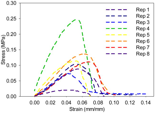
Uniaxial material testing on dendrimer fiber mats was attempted with the MTS Bionix 200 Mechanical Testing System [20, 31]. Stress-strain curves of mPEG-G3.0 (32:1) fiber scaffolds are shown in Figure 4. Electrospun mPEG-G3.0 (32:1) fibers exhibited poor mechanical properties in terms of peak load (0.19 ± 0.09 N), peak stress (0.11 ± 0.07 MPa), modulus (3.0 ± 1.7 MPa), and energy to break (0.05 ± 0.03 N×mm). However, insufficient data was acquired for mPEG-G3.0 (16:1) fiber mat produced using the same method because the mat’s thickness (0.1 ± 0 mm) was much less than mPEG-G3.0 (32:1) mat’s thickness (0.7 ± 0.2 mm). Therefore, it was difficult to preserve mat structure during the sample preparation. As a result, mPEG-G3.0 (16:1) fiber mats were neither thick enough nor reproducable for accurate tensile measurements.
Figure 4.
Stress-strain curves of mPEG-G3.0 (32:1) fiber scaffolds (n=8).
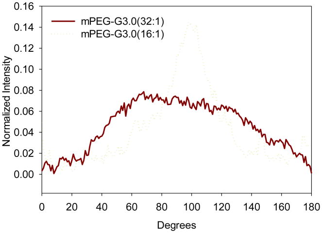
The fast Fourier transform (FFT) technique was conducted to characterize the degree of fiber alignment and anisotropy following the work by Ayers et al.[27] In particular, this analysis was completed by converting SEM image information from the time domain to a discrete frequency domain. The output image after FFT is grayscale pixels within a circle that has varying intensities with respect to its angle about the circle’s central point [27]. Image conversion and analysis was done by using Image J. Distinct peaks in the FFT plots indicates fiber alignment. According to the FFT analysis result (Figure 5), the peak normalized intensities of mPEG-G3.0 (32:1) and mPEG-G3.0 (16:1) fibers are 0.14 and 0.08, respectively. This result quantitatively confirms that mPEG-G3.0 (16:1) scaffold possesses a higher degree of fiber alignment, which, in turn, leads to a less porous structure as evidenced by smaller pore size. A higher degree of fiber alignment can also enable an anisotropic scaffold that can better withstand uniform axial loads and provide signaling cues for changes in cell proliferation, migration and phenotype [14, 32].
Figure 5.
Pixel intensity plots with respect to the angle of acquisition for electrospun mPEG-G3.0 fibers.
Overall, the mPEG-G3.0 fiber scaffolds exhibit poor mechanical properties, which may limit the scaffold’s stability to promote cellular activity and controlled release in tissue engineering and drug delivery applications, respectively. To improve the physical properties of dendrimer fiber scaffolds, additional polymers such as PLGA poly(lactic-co-glycolic acid) can be coupled to PEG to form PLGA-PEG copolymers on the dendrimer surface for drug delivery applications[33]. PLGA has high mechanical strength and elasticity in an early time course [30]. Its material properties such as fiber diameter, hydrophilicity and elasticity can be controlled by changing its polymer concentration or ratio of lactic to glycolic acid. However, optimization of these electrospinning additives is necessary to improve the physical properties while maintaining the original properties of the mPEG-G3.0 conjugates. In addition, dendrimer surface groups may be chemically functionalized to form a cross-linked network following electrospinning to further enhance structural stability and mechanical properties of dendrimer fibrous mats.
By theory, a critical concentration (c*) for chain entanglements in solution should be surpassed for successful fiber formation during electrospinning [18]. This parameter can be theoretically estimated based on Equation 1:
| [28] | (1) |
where M is molecular weight, NA is the Avogadro number, and Rg is the radius of gyration of the polymer and can be estimated using Equation 2.
| [34] | (2) |
Although PEG chain interpenetration among PEGylated dendritic molecules may help with chain entanglements, PEGylated dendrimers are highly compact. Rg of PAMAM G3.0 fully conjugated with PEG of 5000 Da was reported to be 6.27 nm [35], which was only twice the radius of gyration of linear PEG 5000 Da (3.08 nm according to Equation 2 [34]). The same is true for PAMAM G3.0 coupled with mPEG2000 due to an even smaller Rg. Not surprisingly, the highest concentration 40% w/v tested for mPEG-G3.0 (32:1) did not generate fibers. Only droplets deposited on the mandrel were observed during the electrospinning process. Therefore, this estimation suggested a slight chance of electrospinning PEGylated dendrimers alone into fibers due to the difficulty of achieving a critical concentration and further substantiated the use of long PEO as a fiber forming additive. Nonetheless, PEO additive contributed to only 6.25% fiber mass, the structure and properties of the resulting fiber mats are predominately influenced by PEGylated PAMAM dendrimers.
In future work, the in vitro cytocompatibility of the scaffolds will be assessed. Antimicrobial tests such as the Kirby-Bauer assay or turbidity measurement will be utilized to validate the sterility of the scaffold before application. The encapsulation and efficacy of relevant drugs, growth factors and anti-microbial agents will be tested to confirm the functions of bioactive molecules within our novel fiber system. Additional polymers such as PLGA may be incorporated to enhance the scaffold’s mechanical stability. Lastly, in vivo studies will be planned to examine its pre-clinical potential in physiological conditions.
4. Conclusions
In summary, we have successfully fabricated electrospun dendrimer-containing nanocomposite fibers. Morphologically, the mats possessed a uni-modal, non-normal distribution of fibers on the micrometer scale. Fiber alignment is influenced by the degree of PEGylation on the dendrimer surface. The dendrimer fibrous mats show weak mechanical properties that can be improved by adding more stable copolymers such as PLGA without compromising the functionality of dendrimers. In addition, dendrimer surface groups may be chemically functionalized to form a cross-linked network following electrospinning to further enhance structural stability and mechanical properties of dendrimer fibrous mats. Further improvements in the mat’s mechanical properties can make it a potential platform for drug delivery and tissue engineering applications.
Highlights.
Electrospinning of PEGylated PAMAM dendrimers into fibers in the presence of PEO additive.
Morphologically, the dendrimer fiber mats possessed a uni-modal, non-normal distribution of fibers in the microscale.
Fiber alignment is influenced by the degree of PEGylation on the dendrimer surface.
Acknowledgments
This work was supported, in part, by the National Science Foundation CAREER award (CBET0954957) and National Institutes of Health (R01EY024072). D.A. thanks Southern Regional Education Board (SREB)-State Doctoral Scholars Program.
Footnotes
Publisher's Disclaimer: This is a PDF file of an unedited manuscript that has been accepted for publication. As a service to our customers we are providing this early version of the manuscript. The manuscript will undergo copyediting, typesetting, and review of the resulting proof before it is published in its final citable form. Please note that during the production process errors may be discovered which could affect the content, and all legal disclaimers that apply to the journal pertain.
References
- 1.Tomalia DA, Baker H, Dewald J, Hall M, Kallos G, Martin S, Roeck J, Ryder J, Smith P. Polym J (Tokyo) 1985;17(1):117–132. [Google Scholar]
- 2.Tomalia DA, Baker H, Dewald J, Hall M, Kallos G, Martin S, Roeck J, Ryder J, Smith P. Macromolecules. 1986;19(9):2466–2468. [Google Scholar]
- 3.Yang H, Kao WJ. J Biomater Sci Polym Ed. 2006;17(1–2):3–19. doi: 10.1163/156856206774879171. [DOI] [PubMed] [Google Scholar]
- 4.Yang H. Pharm Res. 2010;27(9):1759–1771. doi: 10.1007/s11095-010-0141-7. [DOI] [PMC free article] [PubMed] [Google Scholar]
- 5.Tomalia DA, Uppuluri S, Swanson DR, Li J. Pure and Applied Chemistry. 2000;72(12):2343–2358. [Google Scholar]
- 6.Uppuluri S, Swanson DR, Piehler LT, Li J, Hagnauer GL, Tomalia DA. Advanced Materials. 2000;12(11):796–800. [Google Scholar]
- 7.Tomalia DA. Progress in Polymer Science. 2005;30(3–4):294–324. [Google Scholar]
- 8.Kailasan A, Yuan Q, Yang H. Acta Biomaterialia. 2010;6(3):1131–1139. doi: 10.1016/j.actbio.2009.08.036. [DOI] [PMC free article] [PubMed] [Google Scholar]
- 9.Zhong SP, Yung LYL. Journal of Biomedical Materials Research Part A. 2009;91A(1):114–122. doi: 10.1002/jbm.a.32188. [DOI] [PubMed] [Google Scholar]
- 10.Desai PN, Yuan Q, Yang H. Biomacromolecules. 2010;11(3):666–673. doi: 10.1021/bm901240g. [DOI] [PMC free article] [PubMed] [Google Scholar]
- 11.Pham QP, Sharma U, Mikos AG. Biomacromolecules. 2006;7(10):2796–2805. doi: 10.1021/bm060680j. [DOI] [PubMed] [Google Scholar]
- 12.Wnek GE, Carr ME, Simpson DG, Bowlin GL. Nano Letters. 2003;3(2):213–216. [Google Scholar]
- 13.Liang D, Hsiao BS, Chu B. Adv Drug Deliv Rev. 2007;59(14):1392–1412. doi: 10.1016/j.addr.2007.04.021. [DOI] [PMC free article] [PubMed] [Google Scholar]
- 14.Ayres CE, Jha BS, Meredith H, Bowman JR, Bowlin GL, Henderson SC, Simpson DG. J Biomater Sci Polym Ed. 2008;19(5):603–621. doi: 10.1163/156856208784089643. [DOI] [PubMed] [Google Scholar]
- 15.Pakravan M, Heuzey MC, Ajji A. Polymer. 2011;52(21):4813–4824. [Google Scholar]
- 16.Kriegel C, Kit KM, McClements DJ, Weiss J. Polymer. 2009;50(1):189–200. [Google Scholar]
- 17.Agarwal S, Wendorff JH, Greiner A. Polymer. 2008;49(26):5603–5621. [Google Scholar]
- 18.Shenoy SL, Bates WD, Frisch HL, Wnek GE. Polymer. 2005;46(10):3372–3384. [Google Scholar]
- 19.Madani M, Sharifi-Sanjani N, Iraji-Rad R. Journal of Applied Polymer Science. 2009;113(5):3005–3011. [Google Scholar]
- 20.Dongargaonkar AA, Bowlin GL, Yang H. Biomacromolecules. 2013;14(11):4038–4045. doi: 10.1021/bm401143p. [DOI] [PMC free article] [PubMed] [Google Scholar]
- 21.Zhao Y, Zhu X, Liu H, Luo Y, Wang S, Shen M, Zhu M, Shi X. Journal of Materials Chemistry B. 2014;2(42):7384–7393. doi: 10.1039/c4tb01278j. [DOI] [PubMed] [Google Scholar]
- 22.Malik N, Wiwattanapatapee R, Klopsch R, Lorenz K, Frey H, Weener JW, Meijer EW, Paulus W, Duncan R. Journal of Controlled Release. 2000;65(1–2):133–148. doi: 10.1016/s0168-3659(99)00246-1. [DOI] [PubMed] [Google Scholar]
- 23.Jevprasesphant R, Penny J, Jalal R, Attwood D, McKeown NB, D’Emanuele A. Int J Pharm. 2003;252(1–2):263–266. doi: 10.1016/s0378-5173(02)00623-3. [DOI] [PubMed] [Google Scholar]
- 24.Yang H, Lopina ST, DiPersio LP, Schmidt SP. J Mater Sci: Mater Med. 2008;19(5):1991–1997. doi: 10.1007/s10856-007-3278-0. [DOI] [PubMed] [Google Scholar]
- 25.Ryan SM, Mantovani G, Wang X, Haddleton DM, Brayden DJ. Expert Opin Drug Deliv. 2008;5(4):371–383. doi: 10.1517/17425247.5.4.371. [DOI] [PubMed] [Google Scholar]
- 26.Yang H, Morris JJ, Lopina ST. J Colloid Interface Sci. 2004;273(1):148–154. doi: 10.1016/j.jcis.2003.12.023. [DOI] [PubMed] [Google Scholar]
- 27.Ayres C, Bowlin GL, Henderson SC, Taylor L, Shultz J, Alexander J, Telemeco TA, Simpson DG. Biomaterials. 2006;27(32):5524–5534. doi: 10.1016/j.biomaterials.2006.06.014. [DOI] [PMC free article] [PubMed] [Google Scholar]
- 28.Yu JH, Fridrikh SV, Rutledge GC. Polymer. 2006;47(13):4789–4797. [Google Scholar]
- 29.Deitzel JM, Kleinmeyer J, Harris D, Beck Tan NC. Polymer. 2001;42(1):261–272. [Google Scholar]
- 30.Barnes CP, Sell SA, Boland ED, Simpson DG, Bowlin GL. Adv Drug Deliv Rev. 2007;59(14):1413–1433. doi: 10.1016/j.addr.2007.04.022. [DOI] [PubMed] [Google Scholar]
- 31.Aduba DC, Hammer JA, Yuan Q, Yeudall WA, Bowlin GL, Yang H. Acta Biomaterialia. 2013;9(5):6576–6584. doi: 10.1016/j.actbio.2013.02.006. [DOI] [PMC free article] [PubMed] [Google Scholar]
- 32.Yang F, Murugan R, Wang S, Ramakrishna S. Biomaterials. 2005;26(15):2603–2610. doi: 10.1016/j.biomaterials.2004.06.051. [DOI] [PubMed] [Google Scholar]
- 33.Cheng J, Teply BA, Sherifi I, Sung J, Luther G, Gu FX, Levy-Nissenbaum E, Radovic-Moreno AF, Langer R, Farokhzad OC. Biomaterials. 2007;28(5):869–876. doi: 10.1016/j.biomaterials.2006.09.047. [DOI] [PMC free article] [PubMed] [Google Scholar]
- 34.Devanand K, Selser JC. Macromolecules. 1991;24(22):5943–5947. [Google Scholar]
- 35.Hedden RC, Bauer BJ. Macromolecules. 2003;36(6):1829–1835. [Google Scholar]


