

Abstract
Assembly of carbon nanomaterials into three-dimensional (3D) architectures is necessary to harness their unique physiochemical properties for tissue engineering and regenerative medicine applications. Herein, we report the fabrication and comprehensive cytocompatibility assessment of 3D chemically crosslinked macro-sized (5–8 mm height and 4–6 mm diameter) porous carbon nanotube (CNT) scaffolds. Scaffolds prepared via radical initiated thermal crosslinking of single- or multi- walled CNTs (SWCNTs and MWCNTs) possess high porosity (>80%), and nano-, micro- and macro-scale interconnected pores. MC3T3 pre-osteoblast cells on MWCNT and SWCNT scaffolds showed good cell viability comparable to poly(lactic-co-glycolic) acid (PLGA) scaffolds after 5 days. Confocal live cell and immunofluorescence imaging showed that MC3T3 cells were metabolically active and could attach, proliferate and infiltrate MWCNT and SWCNT scaffolds. SEM imaging corroborated cell attachment and spreading and suggested that cell morphology is governed by scaffold surface roughness. MC3T3 cells were elongated on scaffolds with high surface roughness (MWCNTs) and rounded on scaffolds with low surface roughness (SWCNTs). The surface roughness of scaffolds may be exploited to control cellular morphology, and in turn govern cell fate. These results indicate that crosslinked MWCNTs and SWCNTs scaffolds are cytocompatible, and open avenues towards development of multifunctional all-carbon scaffolds for tissue engineering applications.
Keywords: cytotoxicity, scaffolds, carbon nanotubes, three dimensional, tissue engineering
1. Introduction
Tissue engineering scaffolds should ideally provide suitable 3D microenvironment with desirable mechanical support for cell proliferation and extracellular matrix (ECM) deposition. The bulk-, micro-, and nano-scale material and biochemical properties (e.g. mechanical stiffness, pore architecture, topography, covalent functionalization with proteins, growth factors, and therapeutic ligands) of scaffolds play an important role in regulating cellular functions such as attachment, proliferation, differentiation, and tissue maturation [1–4]. Scaffolds are routinely fabricated using biodegradable polymers such as poly(lactic-co-glycolic) acid, poly(propylene fumarate), poly(hydroxypropyl methacrylate) etc. using various methods such as rapid prototyping[5], electrospinning[6], freeze drying[7], phase separation[8], solvent casting and particulate leaching[9], gas foaming[10], and sol-gel crosslinking[11] for applications in bone, heart, skin, muscle, and other tissue engineering [12]. However, the intrinsic material properties of most current scaffolds generally lack additional multifunctional attributes such as ability to induce/guide specific cellular processes (such as differentiation, specific protein expression), support non-invasive longitudinal diagnosis/monitoring of tissue regeneration, and permit stimulus-based drug and gene delivery [13].
Carbon nanomaterials such as fullerenes, carbon nanotubes and graphene exhibit excellent physiochemical properties such as high mechanical strength, and electrical conductivity as well as unique electromagnetic, opto-acoustic response, and thus, their multifunctional characteristics have been exploited for several biomedical applications such as bioimaging[14–16], stem cell applications[17, 18], drug and gene delivery[19, 20], and photodynamic therapy [21, 22]. They have also been incorporated into polymeric scaffolds as mechanical reinforcing agents [23, 24] or contrast agents [25] to improve non-invasive imaging of the structural properties and biological response of polymeric scaffolds (e.g. porosity, vascularization) under physiological conditions. Thus, the assembly of these carbon nanostructures into three-dimensional (3-D) architectures would harness their physio-chemical properties towards the development of the next-generation tissue engineering scaffolds.
Indeed, there has been a growing interest in assembling carbon nanomaterials into various two- and three-dimensional architectures for the fabrication of next-generation of biomedical devices and implants [26–35]. For example, carbon nanotubes and graphene have been assembled into two-dimensional films (using vacuum filtration and chemical vapor deposition (CVD) methods) and 3D foams (using CVD and sacrificial template-transfer methods) and their cytocompability has been examined for applications in bone, neuron and cardiac tissue engineering [26–38]. However, these methods exhibit several limitations. CVD method requires very specific substrates capable of withstanding high temperatures and pressure [39]. Vacuum filtration and spray coating methods can produce 2D substrates that may not be suitable for tissue engineering of larger organs that require three-dimensional scaffolds [32, 40]. In general, the above methods do not allow control over tuning the pore size or porosity of substrates. Thus, most of the cytocompatibility studies using above mentioned carbon nanotube or graphene films and foams have mainly been restricted to their surface. The propensity of films and foams prepared using these methods to allow cellular infiltration; an important characteristic of a scaffold for tissue regeneration still needs to be demonstrated. Additionally, these approaches may present a practical challenge to fabricate macro-scale scaffolds (at least >1mm in all 3 dimensions) either due to scalability issues, or high operational costs. Furthermore, a general limitation of these methods is that, in the absence of strong chemical bonds between the individual nanomaterials, the structural integrity of architectures assembled relies mainly on weak Van der Wall forces or on physical entanglement of the nanoparticles, and is vulnerable to dissociation under in vivo physiological shear forces. The assembly of carbon nanomaterials into mechanically robust 3D (especially with sizes >1 mm in all three dimensions) macroporous tissue engineering scaffolds with tunable porosity across various lengths (macro, micro and nanoscopic) would constitute a significant advancement.
Recently, we reported a simple scalable method to fabricate chemically-crosslinked macroscopic, 3-D, free standing, all-carbon architectures using fullerenes, single- and multi-walled carbon nanotubes, and graphene as the starting materials [41]. The architectures, prepared by radical initiated thermal crosslinking of the sp2 carbon bonds, and annealing of these carbon nanostructures, possess nano-, and micro- scale- interconnected pores, robust structural integrity, and stability. The fullerene, carbon nanotube and graphene structures show topography that is distinctly different. Varying the amount of radical initiator can control the porosity of the three-dimensional architectures. The results demonstrated that this method could be used as a versatile method for 3-D assembly of carbon nanostructures with pi bond networks to design porous and complex geometries tailored towards specific electronic, material science or biomedical applications.
Towards the development of multifunctional 3D scaffolds for tissue engineering applications, the objectives of this study were: (1) to fabricate and characterize two types of porous all-carbon scaffolds prepared using single- and multi- walled carbon nanotubes (SWCNTs and MWCNTs) employing the aforementioned method and (2) to characterize the cytocompatibility of these scaffolds using MC3T3 pre-osteoblast cells. Specifically, we examine the cell viability, adhesion, proliferation and infiltration of MC3T3 cells on 3D MWCNT and SWCNT scaffolds. Porous polymeric scaffolds prepared using the biodegradable biocompatible polymer poly (lactic acid co-glycolic acid) (PLGA) were used as controls since PLGA is a component of FDA approved medical devices.
2. Materials and methods
2.1 Fabrication of PLGA, MWCNT and SWCNT scaffolds
MWCNTs (Cat. No. 659258, Sigma–Aldrich, NY, USA), SWCNTs (Cat. No. 0101, CheapTubes Inc., NY, USA), PLGA (Cat. No. 23986, Polysciences Inc., PA, USA), benzoyl peroxide (Cat. No. 179981, BP, Sigma–Aldrich, NY, USA) and chloroform (Cat. No. BPC297, CHCl3, Fisher Scientific, PA, USA) were used as purchased. The molecular weight of PLGA was ~12–16 KDa, Polydispersity Index (PDI) was 1.8 and copolymer ratio was 50:50 poly(dl-lactide/glycolide). The diameter (D) × length (L) of MWCNTs were 110–170 nm × 5–9 μm and SWCNTs were 1–4 nm × 5–30 μm. Porous PLGA scaffolds with ~ 85% porosity were fabricated using a thermal-crosslinking particulate-leaching technique using NaCl as the porogen as described elsewhere [42]. MWCNT and SWCNT scaffolds were fabricated by mixing nanomaterials with BP at a mass ratio of MWCNT/SWCNT:BP = 1:0.05. CHCl3 was added to the mixture to dissolve BP and the slurry was subjected to bath sonication (Ultrasonicator FS30H, Fischer Scientific, Pittsburgh, PA) for 15 minutes to ensure uniform dispersion. Post sonication, the slurry was poured into custom machined Teflon® molds (cylinder, length = 1.2 mm, diameter = 6 mm) and incubated at 60°C for 24 h. Post incubation, the MWCNT and SWCNT scaffolds were obtained by disassembling the molds. For purification (to remove the excess BP), scaffolds were subjected to series of washing (CHCl3 washes) and heating steps (150°C for 30 minutes). PLGA scaffolds were not washed with CHCl3, as they would dissolve in the solvent.
2.2 Scanning electron microscopy (SEM)
To characterize the morphology of scaffolds, SEM imaging was performed using a JOEL 7600F Analytical high resolution SEM at the Center for Functional Nanomaterials, Brookhaven National Laboratory, New York. PLGA, MWCNT and SWCNT scaffolds were placed on double-sided conductive carbon tape and sputter coated with 3 nm of silver (Ag). SEM was operated at 5 kV accelerating voltage and images were captured using a secondary electron imaging (SEI) detector.
2.3 Micro-computed tomography (microCT)
MicroCT was used to quantify the micro-porosity of PLGA, MWCNT and SWCNT scaffolds using a previously reported protocol [41, 43]. High resolution microCT scanning was performed using a microCT 40 system (Scanco Medical AG, Bassersdorf, Switzerland) at an energy and intensity level corresponding to 55 kV voltage and 145 μA current with 300 ms integration time for 1000 projections. A Gaussian filter was used to suppress noise. The scaffold was isolated from the background, using a thresholding procedure that was specific to each material. The values to segment scaffold from background were optimized individually by comparing the 2D gray scale image of a single slice of a material with the thresholded image. Three different regions covering a circular area of 1 mm2 and a depth of 0.5 mm were chosen in the center to minimize the inclusion of edge artifacts. Total volume (TV), scaffold volume (SV) and scaffold volume fraction (SV/TV) were determined for each scaffold. The mean and standard deviations for these three different regions were used for statistical comparisons. Porosity values were determined as:
2.4 Image processing
2.4.1 Image processing for porosity analysis
Image processing toolbox in MATLAB (MathWorks®, MA, USA) was used to quantify the nano-porosities of MWCNT and SWCNT scaffolds. SEM images were cropped to remove the scale bar and subjected to processing steps such as thresholding, edge detection, filteration, erosion and dilation and quantification of region properties [41, 44, 45]. Porosity was calculated for n=5 images using the formula:
2.4.2 Image processing for surface roughness
Surface roughness values of MWCNT and SWCNT scaffolds were determined by image processing of a series of SEM images acquired at different regions of the scaffolds using ImageJ (Bethesda, MD, USA). Arithmetic (Ra) and mean roughness (Rq) values were determined for n=10 images by a roughness calculation plugin (authored by Gary Chinga (gary.chinga@pfi.no) and Bob Dougherty; http://rsb.info.nih.gov/ij/plugins/roughness.html) that determines the surface peaks and valleys altitude to calculate roughness values using the following equations:
2.5 Cell culture
National Institutes of Health mouse MC3T3 pre-osteoblast cells (MC3T3 cells, ATCC, Manassas, VA, USA) were used for cytocompatibility studies. MC3T3 cells (passages 15–19) were grown in minimum essential medium alpha (MEM-α, Gibco Life Technologies) media, supplemented with 10 vol. % fetal bovine serum (FBS, Gibco Life Technologies, NY, USA) and 1 vol. % antibiotics (penicillin- streptomycin, Gibco Life Technologies, NY, USA). Media was changed twice a week, and cells were maintained at 37°C in a humidified environment of 5% CO2-95% O2. For cytocompatibility studies, purified MWCNT and SWCNT scaffolds were washed with CHCl3 and placed in an oven at 110°C followed by a series of washes (3X) with CHCl3 (to remove residual BP) and a graded series of ethanol (100%-70%). PLGA scaffolds were only washed with graded series of ethanol, not CHCl3. The scaffolds (PLGA, MWCNT and SWCNT) were then subjected to UV sterilization for 24 hours followed by washes with phosphate buffered saline (PBS) and cell culture media. For pre-wetting, the scaffolds were incubated with cell culture media for 24 hours prior to cell seeding. MC3T3 cells were trypsinized, resuspended in MEM-α, and seeded on the scaffolds at a density of 250,000 cells/scaffold in 30 μl media (added in 2 intervals of 15 μl). Cells were allowed to attach on the scaffolds for 2 hours in a non-adherent 24-well plate before addition of cell culture media (1 ml) to each well. The cells were cultured for 1, 3 and 5 days on the scaffolds to characterize initial cell attachment, proliferation, and spreading/infiltration, respectively.
2.6 Lactate dehydrogenase (LDH) assay
LDH assay is used for the quantification of cell death as a measure of membrane integrity of cells. LDH assay was performed using a commercial LDH kit (TOX-7, Sigma Aldrich, NY, USA) as per manufacturer’s instructions. Briefly, after each time point (1, 3 and 5 days), 50 μl media was collected from each well of the 24-well plate (n=6 for each scaffold group) and transferred to a fresh 96-well plate. A total of 100 μl of LDH assay mixture was added to each well and incubated in dark for 45 minutes. To stop the reaction, 1N HCl (10% volume) was added to each well. Absorbance values were recorded using a 96 well plate reader (Molecular Devices, CA, USA) at 490 nm. Positive control cells (100% dead) were prepared by incubating MC3T3 cells grown on tissue culture polystyrene with lysis buffer for 45 minutes before centrifugation. Cells cultured on PLGA scaffolds served as the baseline control. Total LDH release (% of positive control) was expressed as the percentage of (ODtest - ODblank)/(ODpositive - ODblank), where ODtest is the optical density of cells cultured on PLGA, MWCNT or SWCNT scaffolds, ODblank is the optical density of 96-well plate without cells, and ODpositive is the optical density of positive control (100% dead cells). Absorbance of blank culture media was measured for baseline correction.
2.7 Calcein-AM fluorescence imaging
Calcein – AM (calcein acetoxymethyl ester) upon internalization by live cells is converted to calcein (a green fluorescent dye) due to the hydrolytic removal of acetoxymethyl ester group by intracellular esterases. Therefore, calcein selectively stains live cells that can be visualized using a fluorescence microscope. After 1, 3, and 5 days, media was removed and scaffolds were washed with PBS. 1 ml of Calcein-AM dye (4μM) was added to each well and incubated at 37°C in dark for 20 minutes. The scaffolds were transferred to 35 mm glass bottom dishes (Mattek Corporation, Ashland, MA) and imaged by a confocal laser-scanning microscope (Zeiss LSM 510 Meta NLO Two-Photon) using Zeiss LSM Image Browser software (version 4.2, Carl Zeiss Microimaging, Thornwood, NJ).
2.8 Immunofluorescence for focal adhesion and cell proliferation
Immunofluorescence was performed as reported previously [40]. Briefly, glutaraldehyde fixed cells on PLGA, MWCNT, and SWCNT scaffolds were washed with PBS and incubated with 2% glycine for 5 minutes for blocking. The scaffolds were placed in 0.5% Triton-X-100 permeabilizing buffer (composition: 10.3 g sucrose, 0.29 g NaCl, 0.4 g Hepes buffer, 0.06 g MgCl2, and 0.5 ml Triton-X-100 in 100 ml of DI water) for 25 minutes. Scaffolds were then washed with immunofluorescence buffer (IFB, 0.1% Triton-X-100 and 0.1% BSA in PBS) and incubated with commercially available monoclonal antibodies. Scaffolds were incubated for 1 hour with either anti-proliferating Ki-67 antibody (2 μl/ml in IFB, Cat. No. MA5-14520, Thermo Scientific, New York, USA) for cell proliferation analysis or monoclonal anti-vinculin antibody (2 μl/ml in IFB, Cat. No. V4139, Sigma Aldrich, NY, USA) for visualization of focal adhesion sites. After 1 hour of incubation with primary antibodies, the scaffolds were washed with IFB (3X) and incubated with secondary antibody (anti-rabbit TRITC, 2 μl/ml in IFB, Cat. No. T6778, Sigma Aldrich, New York, USA) for 1 hour. Scaffolds were then washed with IFB (3X) and the cytoplasm was stained with FITC-conjugated phalloidin (2 μl/ml in PBS) for 1 hour to visualize actin filaments (cytoskeleton). Samples were imaged using a confocal laser-scanning microscope (Zeiss LSM 510 Meta NLO Two-Photon) equipped with Zeiss LSM Image Browser software (version 4.2, Carl Zeiss Microimaging, Thornwood, NJ).
2.9 SEM imaging for cellular attachment
To visualize cell attachment on scaffolds, glutaraldehyde fixed cells on PLGA, MWCNT and SWCNT scaffolds were subjected to dehydration steps using graded ethanol washes (70%–100%), air dried, and vacuum dried for 24 hours. Scaffolds were then sputter coated with 3 nm of silver (Ag) and imaged using a JOEL 7600F Analytical high resolution SEM (Center for Functional Nanomaterials, Brookhaven National Laboratory, New York) at an accelerating voltage of 2 kV.
2.10 Image processing to assess cellular infiltration
Z-stacks of calcein stained MC3T3 cells on PLGA, MWCNT and SWCNT scaffolds were acquired using a confocal laser-scanning microscope (Zeiss LSM 510 Meta NLO Two-Photon). Individual Z-stacks were then imported to ImageJ (Bethesda, MD, USA) and subjected to spectral coding using a time-lapse color coder plugin to false-color each slice as a function of depth (Z-height, i.e. depth of cellular infiltration). The multiple spectrally color-coded slices of Z-stacks were then compressed to form one composite image and reported.
2.11 Statistical analysis
Data is reported as mean ± standard deviation. Statistical analysis was performed for a 95% confidence interval (p <0.05) using students ‘t’ test. To analyze the differences between the groups, one-way anova followed by Tukey Kramer post hoc analysis was performed.
3. Results
3.1 Fabrication of PLGA, MWCNT and SWCNT scaffolds
PLGA scaffolds with 85% porosity were fabricated using an established procedure of thermal crosslinking particulate-leaching technique using NaCl as the porogen [42]. MWCNT and SWCNT scaffolds were fabricated using radical initiated thermal-crosslinking procedure [41]. Figure 1 displays the digital images of PLGA, MWCNT and SWCNT scaffolds used for cytocompatibility studies. The scaffolds are 3D porous are cylinders with ~ 5–8 mm in height and ~ 4–6 mm diameter. The scaffolds sizes are smaller than the molds since the molds were not filled completely to facilitate MWCNT and SWCNT slurry handling and disassembly of the molds for scaffold retrieval. For cytocompatibility studies, the scaffolds were cut into smaller 3D cylinders of ~ 4 mm height to ensure uniformity between all the groups.
Figure 1.
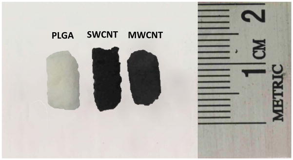
Optical images of representative three-dimensional porous poly(lactic-co-glycolic) acid, single walled carbon nanotube and multi walled carbon nanotube scaffolds prepared as cylinders (5 mm diameter, ~8–10 mm length).
3.2 Characterization of scaffolds
3.2.1 Scanning electron microscopy
EM was used for the morphological characterization of scaffolds. Figure 2 shows cross-sectional SEM images of PLGA, MWCNT and SWCNT scaffolds. All scaffolds possess porous architecture and pores appear well interconnected. PLGA scaffolds (Figure 2A) show characteristic cubic pore architecture of pore sizes between 300–500 μm, corresponding to the size distribution of NaCl crystals. Large openings and interconnected porous architecture are clearly visible. MWCNT and SWCNT scaffolds (Figure 2B and C, respectively) show interconnected MWCNT and SWCNT networks that form the 3D architecture. The MWCNT and SWCNT networks appear highly porous with irregularly shaped interconnected pores, and formations of junctions are also clearly visible (yellow arrows, Figure 2B and C).
Figure 2.

Representative scanning electron microscopy images of (A) poly(lactic-co-glycolic) acid, (B) multi walled carbon nanotube and (C) single walled carbon nanotube scaffolds. Yellow arrows images (B) and (C) correspond to the formation of nanoscale junctions (crosslinks) between CNTs.
3.2.2 Microcomputed tomography (porosity)
MicroCT is a well-established method to determine the porosity of 3D polymeric and carbon nanotube scaffolds [41, 42]. Figures 3A–C display the reconstructed microCT images of cylindrical sections (1 mm2 area, 0.5 mm height) of PLGA, MWCNT and SWCNT scaffolds. The analysis of microCT images determined macro-pore sizes between 300–500 μm for PLGA scaffolds and between 100–400 μm for MWCNT and SWCNT scaffolds. The porosity values of PLGA, MWCNT and SWCNT scaffolds, determined by microCT were 86.61 ± 1.91%, 91.69 ± 1.43% and 83.79 ± 5.75%, respectively (Table 1). It should be noted that the white and grey solid interconnect structures in Figures 3B and C possess nanoscale pores that cannot be visualized by microCT due to a resolution of 6 μm. These pores are clearly visualized by SEM imaging (Figure 2B and C).
Figure 3.
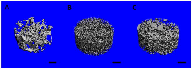
Representative three-dimensional microcomputed tomography reconstructions of subsections of (A) poly(lactic-co-glycolic) acid, (B) multi walled carbon nanotube and (C) single walled carbon nanotube scaffolds. The blue color represents void spaces. Scale bars are 200 μm.
Table 1.
Porosity, pore sizes and surface roughness of scaffolds
| Scaffolds | Porosity | Pore sizes | Surface Roughness | |||
|---|---|---|---|---|---|---|
| MicroCT (%) | SEM Image Processing (%) | MicroCT (μm) | SEM Image Processing (nm) | Arithmetic (Ra, a.u.) | Mean (Rq, a.u.) | |
| PLGA | 86.61±1.91 | - | 300–500 | - | - | - |
| MWCNT | 91.69 ± 1.43 | 45.82 ± 3.59% | 100–400 | 45–850 | 137.19 ± 12.25 | 146.76 ± 12.29 |
| SWCNT | 83.79 ±5.75 | 38.62 ± 2.91% | 100–400 | 20–950 | 89.31 ± 16.05 | 105.07 ± 13.75 |
3.2.3 Image processing for porosity analysis
Nanoscale porosity of scaffolds is vital for the transport of nutrients and exchange of waste metabolites, a feature important for scaffold biocompatibility. Therefore, to quantify the nanoscale porosity values in MWCNT and SWCNT scaffolds, a widely accepted technique was used to perform image processing on a series of SEM images. The porosity values calculated using this method correspond to surface porosity and have been used to estimate the porosities of tissue engineering scaffolds [41, 44, 45]. PLGA scaffolds have macroscopic pores (~300–500 μm) and their porosity is accurately determined using microCT since the pore sizes of PLGA scaffolds are greater than the resolution limit of microCT system. Also, PLGA scaffolds lack nano-porosity, therefore, due to these reasons; SEM image processing was not used to assess the porosity of PLGA scaffolds. The porosity values of MWCNT and SWCNT scaffolds were 45.82 ± 3.59% and 38.62 ± 2.91%, respectively (Table 1). The pore sizes determined from this method were between 45 nm – 850 nm for MWCNT scaffolds and 20 nm – 950 nm for SWCNT scaffolds.
3.2.4 Image processing for nanoscale surface roughness analysis
Nanotopography of tissue engineering scaffolds plays a role in regulating cellular function [3, 46]. Therefore, ImageJ was used to characterize the nanoscale surface roughness of MWCNT and SWCNT scaffolds. The arithmetic and mean roughness values are reported in Table 1. These values are based on pixel intensity (not absolute metric units) as the SEM images were 8 bit with a pixel value of 0 a.u. (arbitrary units) represented as black and value of 255 a.u. represented as white. Values in between produce intermediate grey intensities. Therefore, these values can only be used for qualitative comparison between the surface roughness of MWCNT and SWCNT scaffolds. The arithmetic roughness (Ra) values for MWCNT and SWCNT scaffolds are 137.19 ± 12.25 a.u. and 89.31 ± 16.05 a.u., respectively. The mean roughness (Rq) values for MWCNT and SWCNT scaffolds are 146.76 ± 12.29 a.u. and 105.07 ± 13.75 a.u., respectively.
3.3 Cytotoxicity and cell proliferation analysis
3.3.1 LDH Assay
LDH assay measures the amount of cytosolic enzyme lactate dehydrogenase (LDH) released in the cell culture media by apoptotic or necrotic cells (compromised cell membranes). The released LDH present in the media catalyzes the conversion of lactate to pyruvate simultaneously reducing NAD+ to NADH, which subsequently catalyzes the conversion of iodonitrotetrazolium (INT) to a water-soluble formazan product. The red colored formazan product is quantified as a measure of cell death. Figure 4 shows the total LDH released (normalized to positive controls) from MC3T3 cells after 1, 3, and 5 days of culture on PLGA, MWCNT and SWCNT scaffolds. Cells on SWCNT scaffolds show a slightly higher LDH release (~ 58%) compared to live cells grown on tissue culture polystyrene (TCPS, ~ 49%) after day 1. However, in comparison to TCPS controls after days 3 and 5, no significant differences were observed between total LDH released by MC3T3 cells on PLGA, MWCNT and SWCNT scaffolds (LDH release was between ~ 30–40% for all groups).
Figure 4.

Cytotoxicity evaluation using LDH assay after 1, 3, and 5 days of MC3T3 cell culture on poly(lactic-co-glycolic) acid, multi walled carbon nanotube, and single walled carbon nanotube scaffolds. Chart represents total LDH release (%) normalized to positive controls (100% dead cells). Data is represented as means ± standard deviation. Groups with a significant difference (p < 0.05) are marked with “*”.
3.3.2 Calcein-AM staining
Calcein-AM staining is widely used in cell viability assays to selectively stain living eukaryotic cells [14, 21]. Calcein-AM is a non-fluorescent dye, which upon cellular internalization, is converted to green fluorescent calcein due to removal of acetoxymethyl ester group by intracellular esterases, and is retained in the cytoplasm of living cells. Figure 5 shows representative calcein-AM stained images of MC3T3 cells cultured on PLGA (Figure 5A–C), MWCNT (Figure 5D–F) and SWCNT (Figure 5G–I) scaffolds after 1, 3, and 5 days. After 24 hours of incubation, presence of live MC3T3 cells on PLGA, MWCNT and SWCNT scaffolds was be observed, as shown in Figure 5A, D, and G, respectively. Differences in cellular morphology were also observed between groups. Cells on PLGA and MWCNT scaffolds showed elongated spindle shaped morphology whereas cells on SWCNT scaffolds showed circular morphology (day 3, Figure 5H) that begin spreading and retain their characteristic spindle shaped morphology by day 5. However, as clearly noticeable by comparing Figures 5F and I, cells on MWCNT scaffolds appear more elongated than cells on SWCNT scaffolds, Furthermore, for each scaffold group, an increase in the number of green-fluorescent cell number was observed at day 5 compared to day 1.
Figure 5.

Representative calcein-AM stained green fluorescence images of MC3T3 cells on (A–C) poly(lactic-co-glycolic) acid, (D–F) multi walled carbon nanotube and (G–I) single walled carbon nanotube scaffolds after 1, 3, and 5 days of culture. Presence of live cells (green fluorescence) on all scaffold groups can be observed. Scale bars are 200 μm.
3.4 Immunofluorescence analysis
3.4.1 Cell attachment (vinculin - focal adhesion)
Vinculin is a membrane cytoskeletal protein important for the formation of focal adhesion assembly, and has been widely used as a marker to characterize cell-matrix adhesion [47]. Figure 6 shows representative confocal microscopy images of immunofluorescence staining for vinculin protein expressed by MC3T3 cells cultured on PLGA (Figure 6A–C), MWCNT (Figure 6D–F) and SWCNT (Figure 6G–I) scaffolds after 1 day. MC3T3 cells were stained with FITC-conjugated phalloidin for green fluorescence corresponding to actin cytoskeleton (green fluorescence, Figure 6, Panel A) and fluorescently labeled antibodies for vinculin expression (red fluorescence, Figure 6, Panel B). To ascertain co-localization of actin filaments and vinculin protein expression, merged images of panel A and panel B are presented in Figure 6, Panel C. Figure 6A, D, G confirm the expression of vinculin by MC3T3 cells cultured on PLGA, MWCNT and SWCNT scaffolds, respectively. The vinculin protein appears to be co-localized with actin filaments and evenly distributed throughout the cytoplasm (Figure 6C, F, I).
Figure 6.

Representative immunofluorescence images of MC3T3 cells cultured on (A–C) poly(lactic-co-glycolic) acid, (D–F) multi walled carbon nanotube and (G–I) single walled carbon nanotube scaffolds after 1 day stained green (calceinAM) for actin cytoskeleton (Panel A) and red (rhodamine conjugated mAb) for focal adhesions, i.e. vinculin protein (Panel B). Panel C shows superimposed images of panels A and B showing the co-localization of actin filaments and vinculin protein.
3.4.2 Cell proliferation (Ki-67 - cell proliferation marker)
Ki-67 is an antigen expressed during the active phases of cell cycle (G1, S, G2 and mitosis) and absent during the G0 phase, therefore, it has been widely used as a marker of cell proliferation [48]. Figure 7 shows representative confocal microscopy images of immunofluorescence staining for Ki-67 expression by MC3T3 cells cultured on PLGA (Figure 7A–C), MWCNT (Figure 7D–F) and SWCNT (Figure 7G–I) scaffolds after 5 days. MC3T3 cells were stained with FITC-conjugated phalloidin for actin cytoskeleton (green fluorescence, Figure 7, Panel A) and fluorescently labeled antibodies for Ki-67 expression (red fluorescence, Figure 7, Panel B). Panel C in Figure 7 shows merged images for actin cytoskeleton and Ki-67 protein. Ki-67 expression can be observed throughout the cytoplasm and nucleus for cells seeded on PLGA (Figure 7C and D), MWCNT (Figure 7E and F) and SWCNT (Figure 7H and I) scaffolds implying that MC3T3 cells on all scaffold groups were metabolically active and proliferating.
Figure 7.

Representative immunofluorescence images of MC3T3 cells cultured on (A–C) poly(lactic-co-glycolic) acid, (D–F) multi walled carbon nanotube and (G–I) single walled carbon nanotube scaffolds after 5 days stained green (calceinAM) for actin cytoskeleton (Panel A) and red (rhodamine conjugated mAb) for cell proliferation marker, i.e. Ki-67 protein (Panel B). Panel C shows superimposed images of panels A and B showing the co-localization of actin filaments and Ki-67 protein.
3.5 Cell attachment and morphology (SEM)
SEM was used for the characterization of cellular adhesion and morphology. Figure 8 shows representative SEM images of MC3T3 cells on PLGA (Figure 8A, D), MWCNT (Figure 8B, E) and SWCNT (Figure 8C, F) scaffolds after 5 days. The cells appear horizontally spread out on PLGA and MWCNT scaffolds, and rounded on SWCNT scaffolds (black arrows, Figure 8D, E, and F, respectively). Cells on all the scaffolds show morphology that suggest formation of cytoplasmic extensions and membrane projections with no preferential direction (yellow arrows, inset, Figure 8D, E, and F). Cells appear more elongated on MWCNT scaffolds and rounded on SWCNT scaffolds (Figure 8E and F). Additionally, several nanoscale junctions between cell protrusions and underlying MWCNT and SWCNT networks can be observed (black arrows, Figure 8E and F). The cytoplasmic protrusions appear to be wrapped over and under the MWCNT and SWCNTs bundles (Figure 8E and F).
Figure 8.

Representative SEM images showing adhesion of MC3T3 cells on (A and D) poly(lactic-co-glycolic) acid, (B and E) multi walled carbon nanotube, and (C and F) single walled carbon nanotube scaffolds. Formation of cytoplasmic extensions (filopodia and pseudopodia) can be observed for each scaffold group (inset in images D, E and F).
3.6 Image processing to assess cellular infiltration
Cellular infiltration inside PLGA, MWCNT and SWCNT scaffolds was assessed by image processing of confocal Z-stacks of calcein-AM stained MC3T3 cells [49]. Each individual stack was subjected to spectral-color coding steps to false color-code the cells as a function of Z-depth i.e. cellular infiltration. Figure 9A, B, and C show infiltration of cells on PLGA, MWCNT and SWCNT scaffolds, respectively. Presence of cells can be detected upto a depth of ~200–300 μm for each scaffold group. Image acquisition beyond that depth was not possible due to limitations with laser penetration inside 3D scaffolds.
Figure 9.
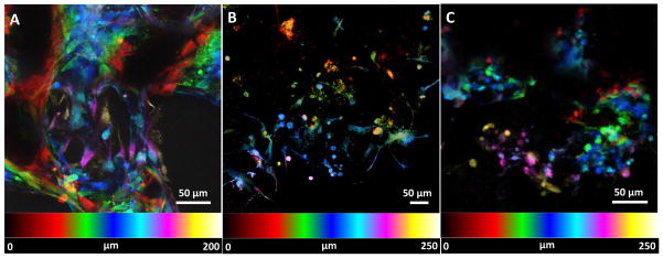
Representative spectrally color coded images of calcein-AM stained MC3T3 cells a function of confocal Z-depth (i.e. cellular infiltration) after 5 days of culture on (A) poly(lactic-co-glycolic) acid, (B) multi walled carbon nanotube and (C) single walled carbon nanotube scaffolds. Presence of cells can be detected upto a depth of ~200–300 μm for each scaffold group.
4. Discussions
The goal of this study was to fabricate and assess the cytocompatibility of 3D, macro-sized, porous all-carbon scaffolds fabricated using MWCNTs and SWCNTs as building blocks. The porous cylindrical architecture of PLGA, MWCNT and SWCNT scaffolds is shown in Figure 1. MWCNT and SWCNT were assembled into 3D scaffolds using a radical initiated thermal crosslinking method as reported previously [41]. BP is a widely used radical initiator for free-radical polymerization reactions and has been used for sidewall functionalization of carbon nanotubes [50]. Our previous study postulates the decomposition of BP to yield benzoyl and benzoyloxyl free radical species that attack the C=C double bonds on carbon nanotubes forming reactive sites [41]. These reactive sites serve as inter-nanotube crosslinking centers, resulting in the nanoscale crosslinking of carbon nanotubes, forming a 3D macroscopic architecture [41]. The unreacted BP and other volatile compounds get removed during the purification step (repeated washing steps with CHCl3 and thermal annealing at 150°C for 30 minutes) [41]. The nanomaterial:BP ratio of 1:0.5 was used to fabricate scaffolds with >80% porosity. PLGA scaffolds with ~85% porosity were fabricated using a thermal crosslinking particulate leaching and were used as positive controls. For effective mass transfer, exchange of nutrients and waste metabolites and ECM deposition, tissue engineering scaffolds with ~80–90% porosities are desirable [51]. Scaffolds with porosities >90% typically lack the necessary mechanical properties required for load bearing bone tissue engineering applications.
Chemical characterization of CNT scaffolds using Raman spectroscopy and X-ray photoelectron spectroscopy (XPS) has been reported in our previous study [41]. Those results determined the chemical composition of CNT scaffolds to comprise of carbon and oxygen as the primary elements (94.1% and 5.54% respectively). Further, it was also confirmed that the radical initiated crosslinking of CNTs is due to the disruption of sp2 bonded C=C bonds, and also indicated presence of carbonyl, phenyl, and benzoyloxyl functional groups formed during the crosslinking reaction, the π–π interactions between aromatic groups of CNT and phenyl and benzoyloxyl adducts, and the presence of termination by-products of the radical initiated crosslinking reaction. Additionally, those results indicated that during thermal annealing steps, the functional groups, excess BP, and radical by-products are removed resulting in the partial restoration of sp2 (C=C) bonds.
The radical initiated thermal crosslinking method introduces the formation of nanoscale crosslinks between individual and bundled carbon nanotubes (analyzed by high-resolution SEM and TEM) [41]. SEM was performed on PLGA, MWCNT and SWCNT scaffolds (Figure 2) to characterize the morphology and pore architecture of scaffolds and re-confirm the presence of crosslinks between individual MWCNTs and SWCNTs (yellow arrows, Figures 2B and C). Furthermore, the irregularly shaped macro-, micro-, and nano- scale pores of MWCNT and SWCNT scaffolds are clearly noticeable (Figure 2A and B). The pores of PLGA scaffolds are formed due to salt leaching and resemble the characteristic cubic shape of NaCl crystals (Figure 2C).
MicroCT was used to characterize the porosity and pore sizes of PLGA, MWCNT and SWCNT scaffolds, whereas SEM image processing was used only for MWCNT and SWCNT scaffolds. MicroCT is a well-established method to characterize the porosity of polymeric and 3D all-carbon scaffolds [41, 52]. Figure 3A–C shows the 3D reconstruction of cylindrical sections (1 mm2 area, 0.5 mm height) of PLGA, MWCNT and SWCNT scaffolds, respectively. These images clearly confirm the presence of interconnected pores (blue colored voids) in all the scaffolds. The analysis of microCT sections confirms the presence of irregularly shaped interconnected pores, consistently distributed throughout the scaffold. It should be noted that the white and grey solid interconnect structures in Figures 3B and C possess nanoscale pores that cannot be visualized by microCT due to a resolution of 6 μm. These pores are clearly visualized by SEM imaging (Figure 2B and C). To further characterize the nano- and micro-scale porosity of MWCNT and SWCNT scaffolds, SEM image processing was used. The porosity values determined using this method correspond to surface porosities and have been used to estimate porosities of tissue engineering scaffolds [44, 45]. SEM image analysis confirms the macroporous architecture of MWCNT and SWCNT scaffolds and the presence of nano- and micro- scaled interconnected pores. The presence of interconnected macroporous architecture is critical for efficient mass transport (diffusion of nutrients and removal of waste metabolites) and formation of neo-vasculature in the scaffolds upon implantation in vivo. Furthermore, several studies have reported that scaffolds with smaller pore sizes (96–150 μm) allow higher cell attachment compared to scaffolds with greater pore sizes (300–800 μm) that facilitate better bone tissue ingrowth in the scaffolds [53–55]. MicroCT and SEM image processing results suggest that 3D, macroporous, MWCNT and SWCNT scaffolds may permit efficient mass transfer, neovascularization, cellular attachment and bone ingrowth due to presence of interconnected nano-, micro-, and macro-scaled porosity.
Comprehensive in vivo cytotoxicity studies are the necessary first step towards more elaborate and costly in vivo studies that focus on assessing the biocompatibility of 3D MWCNT and SWCNT scaffolds for potential biomedical applications. Since the 3D macroporous MWCNT and SWCNT scaffolds could be utilized as implants for bone tissue engineering applications, they will primarily interact with precursor osteoblasts cells in vivo. Thus, MC3T3 cells, a widely accepted cell line for in vitro bone studies were utilized as model cell lines to evaluate the in vitro cytocompatibility of MWCNT and SWCNT scaffolds [56].
To quantitatively assess the cytotoxicity of MWCNT and SWCNT scaffolds, we performed LDH assay to assess cell death of MC3T3 cells after 1, 3, and 5 days of culture. Porous PLGA scaffolds were used as live controls. LDH assay is a widely recommended method to analyze the cytotoxicity of carbon nanomaterials [14, 19, 57, 58]. It is well known that several cytotoxicity assays (such as MTT, XTT) produce erroneous results due to strong binding of formazan crystals on the nanotube surface [57]. Conversely, LDH assay measures the amount of cytosolic enzyme lactate dehydrogenase released in the media by apoptotic and necrotic cells therefore no interference is observed. We had previously validated the suitability of LDH assay of cytotoxicity studies involving carbon nanoparticles including nanotubes [14, 19, 58]. No significant difference in the total LDH release was observed between PLGA, MWCNT and SWCNT scaffold groups at days 3 and 5, suggesting a good cytocompatibility of MWCNT and SWCNT scaffolds, comparable to the FDA approved PLGA. To further analyze cell viability and corroborate LDH results, we performed calcein-AM staining of MC3T3 cells cultured on PLGA, MWCNT and SWCNT scaffolds after day 5. The bright green fluorescence observed in Figure 5A–I confirms the presence of live MC3T3 cells on all scaffold groups at each time point. Furthermore, an increase in cell number can be observed between 1–5 days for all scaffolds suggesting that MC3T3 cells can proliferate on MWCNT and SWCNT scaffolds. It should be noted that Figure 5A–I shows representative images; similar cell proliferation was observed for at least 3 individual experiments.
Immunofluorescence staining of MC3T3 cells was performed for vinculin (focal adhesion assembly) and Ki-67 (cell proliferation marker) expression to qualitatively confirm cell attachment and proliferation. Cell attachment is critical for adequate functioning of several cellular processes such as cell signaling, migration, maturation, apoptosis etc. [59]. Cells attach to the underlying extracellular matrix (ECM) by the formation of large macromolecular assemblies such as focal adhesion that connect ECM to actin filaments and hemidesmosomes that connect ECM to intermediate filaments. In mammalian cells, vinculin is a membrane cytoskeletal protein in focal adhesion complexes that link integrin molecules to actin cytoskeleton [47, 59]. Figure 6 confirms the expression of vinculin (red fluorescence), evenly distributed throughout the cytoplasm (green fluorescence), suggesting that MC3T3 cells form focal adhesion complexes with the underlying MWCNT and SWCNT networks and PLGA scaffolds. Ki-67 is a cell proliferation marker, expressed during all active phases of cell division (G1, S, G2 and M) and absent during the resting phase (G0) [48]. Therefore, Ki-67 has been extensively used as a marker of cell proliferation. MC3T3 cells on MWCNT and SWCNT scaffolds express Ki-67 protein (red fluorescence, Figure 7) suggesting proliferation of cells on MWCNT SWCNT and PLGA scaffolds. The expression of Ki-67 also provided further evidence that MC3T3 cells on these scaffolds are metabolically active.
Cellular infiltration into 3D scaffolds is important for tissue regeneration. Mierke et. al. have shown that expression of vinculin is critical for cellular infiltration into 3D scaffolds [60]. In our study, expression of vinculin by MC3T3 cells on MWCNT and SWCNT scaffolds suggests that these scaffolds are capable of supporting cellular infiltration into 3D architecture. It is well known that cell infiltration in 3D scaffolds and cell migration on 2D substrates is governed by different mechanisms[47, 60], and variable spatial expression of vinculin is observed for cells cultured on 2D vs. 3D substrates [47]. For example, vinculin and focal adhesion assemblies of cells on 2D planar substrates are aggregated towards the periphery of the cytoplasm. However, Fraley et. al. and others suggest that contrary to cells on 2D substrates, focal adhesion complexes of cells in 3D scaffolds are diffusely distributed throughout the cytoplasm [47, 61]. For cells embedded in a 3D matrix, cytoplasmic extensions and filopodia have a central role in driving cell motility; organized focal adhesions are short lived and small, compared to the lifetime and length of pseudopodia or amplitude and time scale of matrix deformation [47]. SEM analysis (Figure 8) of cells on PLGA, MWCNT and SWCNT scaffolds show the presence of numerous cytoplasmic extensions and filopodia (yellow arrows, inset, Figure 8D, E and F). Migrating cells have also been reported to express cytoplasmic distribution of vinculin [61]. MC3T3 cells on MWCNT and SWCNT scaffolds show numerous filopodia and pseudopodia and a cytoplasmic distribution of vinculin suggesting that 3D MWCNT and SWCNT scaffolds permit cellular infiltration, critical for tissue regeneration. The spectrally color coded images of MC3T3 cells on MWCNT and SWCNT scaffolds (Figure 9) confirm cellular infiltration upto a depth of ~300 μm. However, cells maybe present at greater depths inside MWCNT and SWCNT scaffolds. Image acquisition at greater depths inside the 3D architecture of scaffolds was not possible due to limitations associated with the depth of penetration of the laser. To overcome these limitations, histological sectioning of 3D scaffolds can be used to assess cellular infiltration.
The elongated, spindle like morphology of MC3T3 cells on MWCNT scaffolds (Figure 5F, 8 B) and circular rounded morphology on SWCNT scaffolds (Figure 5I, 8 C) may be attributed to the differences in surface roughness, wherein, MWCNT scaffolds with higher surface roughness and greater nanotube diameter may result in the formation of largely spaced protein-adsorbed MWCNT islands/bundles. These results suggest that nanotopography of MWCNT and SWCNT scaffolds may control/alter cellular behavior. It is well known that nanotopography plays an important role in regulating cellular functions such as cell attachment, proliferation, migration and differentiation, thereby directly influencing metastasis, wound repair and embryogenesis [3, 34, 46]. Tutak et.al. observed increased adhesion of MC3T3 cells on hydrophilic carbon nanotube films with 100 nm surface roughness compared to films with ~60 nm surface roughness [32]. Oh et. al. demonstrated accelerated differentiation of human mesenchymal stem cells (hMSCs) on TiO2 nanotubes with increasing nanotube diameter [62]. Dulgar-Tulloch et. al. cultured hMSCs on ceramics with varying grain sizes (24–1500 nm) and showed that 200 nm grain size was most favorable for hMSC proliferation [63]. In another study, Dalby et. al. showed enhanced bone cell differentiation on randomly ordered poly(methyl methacrylate) nanopits [64]. Nayak et. al. showed enhanced proliferation and differentiation of hMSCs on rough, graphene coated SiO2 substrates and glass slide, compared to their non-graphene deposited counterparts [36]. Although the intricate details of how nanotopography affects cell fate is unknown, these reports suggest that increased nanotopography and surface roughness may result in increased protein adsorption, which in turn can govern cell fate. Based on our results and other reports, we hypothesize that, in order to bind to succeeding MWCNT bundles, cells will stretch and elongate to a greater extent compared to cells binding to closely spaced SWCNT bundles due to small diameter of SWCNTs resulting in a significantly higher cytoplasmic elongation of cells cultured on rough MWCNT scaffolds compared to cells cultured on smooth SWCNT scaffolds. These results coupled with the ability to fine tune surface roughness of 3D carbon nanotube scaffolds by using nanotubes of varying diameters suggest that 3D all-carbon scaffolds may be exploited to control/govern cell fate purely based on nanotopographic cues. In addition, nanostructured scaffolds offer several advantages over conventional polymeric scaffolds such as (1) a single cell can contact millions of nanofibers (for example MWCNTs and SWCNTs), thereby resulting in the effective transmission of subtle topographic cues from the underlying scaffold substrate to the cell and (2) nanotopography and surface roughness of MWCNT and SWCNT scaffolds may result in a better host-implant integration reducing the risk of failure of biomedical implants [65].
To the best of our knowledge, this is the first study on the comprehensive assessment of cytocompatibility (cell viability, adhesion, proliferation and infiltration) of 3D macro-sized (>1mm in all three dimensions) all-carbon scaffolds with macro-, micro- and nano-porosity fabricated by radical initiated thermal crosslinking using MWCNT and SWCNT as building blocks. The results of this study suggest that 3D, all-carbon; MWCNT and SWCNT scaffolds are cytocompatible and opens avenues for further in vivo investigation of these scaffolds for biomedical applications. The assembly of carbon nanomaterials into various 3D, macroscopic, porous architectures is critical to harness the unique physiochemical properties for the fabrication of next-generation of biomedical devices and implants. Apart from the 2D films and 3D foams fabricated using the methods (vacuum filtration, CVD and sacrificial template-transfer) described in the introduction, over the last decade, microscopic 3D carbon nanotube architectures of either aligned or entangled carbon nanotubes have been fabricated [66–68]. Macroscopic scale (>1mm in two or all three dimensions) structures of vertically aligned or entangled networks of pristine CNTs or graphene have also been fabricated using sol-gel reactions and powder-compression approaches [28, 69]. However, the ability of these methods to control the porosity of the 3-D CNT structures or to form covalent bonds between CNTs, an important feature for many biomedical applications, still needs to be determined. Furthermore, the use of toxic surfactants may adversely affect the cytocompatibility of these 3D structures, and the absence of macroporosity (pore size range: 10–200 μm, critical for cellular infiltration and exchange of metabolites), could restrict the suitability of these structures as scaffolds for biomedical applications. Typically, carbon nanomaterial dispersed polymeric scaffolds have been investigated for biomedical applications [9, 52, 70–72], however, compared to these composite architectures, 3D all-carbon scaffolds may possess additional multifunctional attributes. The chemical, physical and electrical properties of these 3D CNT scaffolds could be exploited to develop stimulus responsive scaffolds to deliver drugs[19, 20], electroceuticals applications[73], non-invasively image the scaffolds to track tissue regeneration[74] and control the fate of progenitor cells [17, 18]. Therefore, in a true-sense, 3D macroporous all-carbon scaffolds may be exploited as multifunctional scaffolds for the next generation of tissue engineering and regenerative medicine applications.
Conclusions
3D macroporous all-carbon scaffolds were fabricated using single- and multi-walled carbon nanotubes as building blocks. The 3D SWCNT and MWCNT scaffolds are macroporous architectures containing nano-, micro- and macro-scaled interconnected pores. The scaffolds show good cell viability, attachment, proliferation and cell infiltration. Differences in cell morphology were observed; cells on MWCNT scaffolds were elongated whereas on SWCNT scaffolds were rounded suggesting that scaffold nanotopography may be modulated to control cell morphology. These results taken together suggest that 3D macroporous all-carbon scaffolds fabricated using SWCNT and MWCNTs are cytocompatible and opens avenues for further in vivo investigation of these structures as multifunctional scaffolds for tissue engineering and regenerative medicine applications.
Acknowledgments
This work was supported by the National Institutes of Health (grant no. 1DP2OD007394-01). Research was carried out in part at the Center for Functional Nanomaterials, Brookhaven National Laboratory, New York, which is supported by the U.S. Department of Energy, Office of Basic Energy Sciences, under Contract No. DE-AC02-98CH10886.
References
- 1.Discher DE, Mooney DJ, Zandstra PW. Growth factors, matrices, and forces combine and control stem cells. Science. 2009;324:1673–7. doi: 10.1126/science.1171643. [DOI] [PMC free article] [PubMed] [Google Scholar]
- 2.Engler AJ, Sen S, Sweeney HL, Discher DE. Matrix elasticity directs stem cell lineage specification. Cell. 2006;126:677–89. doi: 10.1016/j.cell.2006.06.044. [DOI] [PubMed] [Google Scholar]
- 3.Dalby MJ, Gadegaard N, Oreffo RO. Harnessing nanotopography and integrin-matrix interactions to influence stem cell fate. Nature materials. 2014;13:558–69. doi: 10.1038/nmat3980. [DOI] [PubMed] [Google Scholar]
- 4.Hui EE, Bhatia SN. Micromechanical control of cell-cell interactions. Proceedings of the National Academy of Sciences of the United States of America. 2007;104:5722–6. doi: 10.1073/pnas.0608660104. [DOI] [PMC free article] [PubMed] [Google Scholar]
- 5.Peltola SM, Melchels FP, Grijpma DW, Kellomaki M. A review of rapid prototyping techniques for tissue engineering purposes. Annals of medicine. 2008;40:268–80. doi: 10.1080/07853890701881788. [DOI] [PubMed] [Google Scholar]
- 6.Nair LS, Bhattacharyya S, Laurencin CT. Development of novel tissue engineering scaffolds via electrospinning. Expert opinion on biological therapy. 2004;4:659–68. doi: 10.1517/14712598.4.5.659. [DOI] [PubMed] [Google Scholar]
- 7.Deville S, Saiz E, Tomsia AP. Freeze casting of hydroxyapatite scaffolds for bone tissue engineering. Biomaterials. 2006;27:5480–9. doi: 10.1016/j.biomaterials.2006.06.028. [DOI] [PubMed] [Google Scholar]
- 8.Lu T, Li Y, Chen T. Techniques for fabrication and construction of three-dimensional scaffolds for tissue engineering. International journal of nanomedicine. 2013;8:337–50. doi: 10.2147/IJN.S38635. [DOI] [PMC free article] [PubMed] [Google Scholar]
- 9.Farshid B, Lalwani G, Sitharaman B. In Vitro Cytocompatibility of One- and Two-Dimensional Nanostructure-Reinforced Biodegradable Polymeric Nanocomposites. Journal of Biomedical Materials Research Part A. 2014 doi: 10.1002/jbm.a.35363. In Press. [DOI] [PMC free article] [PubMed] [Google Scholar]
- 10.Harris LD, Kim BS, Mooney DJ. Open pore biodegradable matrices formed with gas foaming. Journal of biomedical materials research. 1998;42:396–402. doi: 10.1002/(sici)1097-4636(19981205)42:3<396::aid-jbm7>3.0.co;2-e. [DOI] [PubMed] [Google Scholar]
- 11.Gunatillake PA, Adhikari R. Biodegradable synthetic polymers for tissue engineering. Eur Cell Mater. 2003;5:1–16. doi: 10.22203/ecm.v005a01. [DOI] [PubMed] [Google Scholar]
- 12.Langer R, Vacanti JP. Tissue engineering. Science. 1993;260:920–6. doi: 10.1126/science.8493529. [DOI] [PubMed] [Google Scholar]
- 13.Barnes CP, Sell SA, Boland ED, Simpson DG, Bowlin GL. Nanofiber technology: designing the next generation of tissue engineering scaffolds. Advanced drug delivery reviews. 2007;59:1413–33. doi: 10.1016/j.addr.2007.04.022. [DOI] [PubMed] [Google Scholar]
- 14.Lalwani G, Sundararaj JL, Schaefer K, Button T, Sitharaman B. Synthesis, characterization, in vitro phantom imaging, and cytotoxicity of a novel graphene-based multimodal magnetic resonance imaging-X-ray computed tomography contrast agent. Journal of Materials Chemistry B. 2014;2:3519–30. doi: 10.1039/C4TB00326H. [DOI] [PMC free article] [PubMed] [Google Scholar]
- 15.Kanakia S, Toussaint JD, Chowdhury SM, Lalwani G, Tembulkar T, Button T, et al. Physicochemical characterization of a novel graphene-based magnetic resonance imaging contrast agent. International journal of nanomedicine. 2013;8:2821–33. doi: 10.2147/IJN.S47062. [DOI] [PMC free article] [PubMed] [Google Scholar]
- 16.Lalwani G, Cai X, Nie L, Wang LV, Sitharaman B. Graphene-based contrast agents for photoacoustic and thermoacoustic tomography. Photoacoustics. 2013;1:62–7. doi: 10.1016/j.pacs.2013.10.001. [DOI] [PMC free article] [PubMed] [Google Scholar]
- 17.Sitharaman B, Avti PK, Schaefer K, Talukdar Y, Longtin JP. A novel nanoparticle-enhanced photoacoustic stimulus for bone tissue engineering. Tissue engineering Part A. 2011;17:1851–8. doi: 10.1089/ten.tea.2010.0710. [DOI] [PMC free article] [PubMed] [Google Scholar]
- 18.Green DE, Longtin JP, Sitharaman B. The effect of nanoparticle-enhanced photoacoustic stimulation on multipotent marrow stromal cells. ACS nano. 2009;3:2065–72. doi: 10.1021/nn900434p. [DOI] [PubMed] [Google Scholar]
- 19.Mullick Chowdhury S, Lalwani G, Zhang K, Yang JY, Neville K, Sitharaman B. Cell specific cytotoxicity and uptake of graphene nanoribbons. Biomaterials. 2013;34:283–93. doi: 10.1016/j.biomaterials.2012.09.057. [DOI] [PMC free article] [PubMed] [Google Scholar]
- 20.Sun X, Liu Z, Welsher K, Robinson JT, Goodwin A, Zaric S, et al. Nano-Graphene Oxide for Cellular Imaging and Drug Delivery. Nano research. 2008;1:203–12. doi: 10.1007/s12274-008-8021-8. [DOI] [PMC free article] [PubMed] [Google Scholar]
- 21.Lalwani G, Sitharaman B. Multifunctional Fullerene- and Metallofullerene-Based Nanobiomaterials. Nano LIFE. 2013;03:1342003. [Google Scholar]
- 22.Tian B, Wang C, Zhang S, Feng L, Liu Z. Photothermally enhanced photodynamic therapy delivered by nano-graphene oxide. ACS nano. 2011;5:7000–9. doi: 10.1021/nn201560b. [DOI] [PubMed] [Google Scholar]
- 23.Lalwani G, Henslee AM, Farshid B, Lin L, Kasper FK, Qin YX, et al. Two-dimensional nanostructure-reinforced biodegradable polymeric nanocomposites for bone tissue engineering. Biomacromolecules. 2013;14:900–9. doi: 10.1021/bm301995s. [DOI] [PMC free article] [PubMed] [Google Scholar]
- 24.Lalwani G, Henslee AM, Farshid B, Parmar P, Lin L, Qin YX, et al. Tungsten disulfide nanotubes reinforced biodegradable polymers for bone tissue engineering. Acta biomaterialia. 2013;9:8365–73. doi: 10.1016/j.actbio.2013.05.018. [DOI] [PMC free article] [PubMed] [Google Scholar]
- 25.Talukdar Y, Avti P, Sun J, Sitharaman B. Multimodal ultrasound-photoacoustic imaging of tissue engineering scaffolds and blood oxygen saturation in and around the scaffolds. Tissue engineering Part C, Methods. 2014;20:440–9. doi: 10.1089/ten.tec.2013.0203. [DOI] [PMC free article] [PubMed] [Google Scholar]
- 26.Li N, Zhang Q, Gao S, Song Q, Huang R, Wang L, et al. Three-dimensional graphene foam as a biocompatible and conductive scaffold for neural stem cells. Scientific reports. 2013;3:1604. doi: 10.1038/srep01604. [DOI] [PMC free article] [PubMed] [Google Scholar]
- 27.Crowder SW, Prasai D, Rath R, Balikov DA, Bae H, Bolotin KI, et al. Three-dimensional graphene foams promote osteogenic differentiation of human mesenchymal stem cells. Nanoscale. 2013;5:4171–6. doi: 10.1039/c3nr00803g. [DOI] [PMC free article] [PubMed] [Google Scholar]
- 28.Li X, Liu H, Niu X, Yu B, Fan Y, Feng Q, et al. The use of carbon nanotubes to induce osteogenic differentiation of human adipose-derived MSCs in vitro and ectopic bone formation in vivo. Biomaterials. 2012;33:4818–27. doi: 10.1016/j.biomaterials.2012.03.045. [DOI] [PubMed] [Google Scholar]
- 29.Mooney E, Mackle JN, Blond DJ, O’Cearbhaill E, Shaw G, Blau WJ, et al. The electrical stimulation of carbon nanotubes to provide a cardiomimetic cue to MSCs. Biomaterials. 2012;33:6132–9. doi: 10.1016/j.biomaterials.2012.05.032. [DOI] [PubMed] [Google Scholar]
- 30.Nayak TR, Jian L, Phua LC, Ho HK, Ren Y, Pastorin G. Thin films of functionalized multiwalled carbon nanotubes as suitable scaffold materials for stem cells proliferation and bone formation. ACS nano. 2010;4:7717–25. doi: 10.1021/nn102738c. [DOI] [PubMed] [Google Scholar]
- 31.Jan E, Kotov NA. Successful differentiation of mouse neural stem cells on layer-by-layer assembled single-walled carbon nanotube composite. Nano letters. 2007;7:1123–8. doi: 10.1021/nl0620132. [DOI] [PubMed] [Google Scholar]
- 32.Tutak W, Chhowalla M, Sesti F. The chemical and physical characteristics of single-walled carbon nanotube film impact on osteoblastic cell response. Nanotechnology. 2010;21:315102. doi: 10.1088/0957-4484/21/31/315102. [DOI] [PubMed] [Google Scholar]
- 33.Nardecchia S, Serrano MC, Gutiérrez MC, Ferrer ML, del Monte F. Modulating the cytocompatibility of tridimensional carbon nanotube-based scaffolds. Journal of Materials Chemistry B. 2013;1:3064–72. doi: 10.1039/c3tb20253d. [DOI] [PubMed] [Google Scholar]
- 34.Brunner EW, Jurewicz I, Heister E, Fahimi A, Bo C, Sear RP, et al. Growth and proliferation of human embryonic stem cells on fully synthetic scaffolds based on carbon nanotubes. ACS applied materials & interfaces. 2014;6:2598–603. doi: 10.1021/am405097w. [DOI] [PubMed] [Google Scholar]
- 35.Park SY, Park J, Sim SH, Sung MG, Kim KS, Hong BH, et al. Enhanced differentiation of human neural stem cells into neurons on graphene. Advanced materials. 2011;23:H263–7. doi: 10.1002/adma.201101503. [DOI] [PubMed] [Google Scholar]
- 36.Nayak TR, Andersen H, Makam VS, Khaw C, Bae S, Xu X, et al. Graphene for controlled and accelerated osteogenic differentiation of human mesenchymal stem cells. ACS nano. 2011;5:4670–8. doi: 10.1021/nn200500h. [DOI] [PubMed] [Google Scholar]
- 37.Tang M, Song Q, Li N, Jiang Z, Huang R, Cheng G. Enhancement of electrical signaling in neural networks on graphene films. Biomaterials. 2013;34:6402–11. doi: 10.1016/j.biomaterials.2013.05.024. [DOI] [PubMed] [Google Scholar]
- 38.Martinelli V, Cellot G, Fabbro A, Bosi S, Mestroni L, Ballerini L. Improving cardiac myocytes performance by carbon nanotubes platforms. Frontiers in physiology. 2013;4:239. doi: 10.3389/fphys.2013.00239. [DOI] [PMC free article] [PubMed] [Google Scholar]
- 39.Reina A, Jia X, Ho J, Nezich D, Son H, Bulovic V, et al. Large area, few-layer graphene films on arbitrary substrates by chemical vapor deposition. Nano letters. 2008;9:30–5. doi: 10.1021/nl801827v. [DOI] [PubMed] [Google Scholar]
- 40.Patel SC, Lalwani G, Sitharaman B. Fabrication and Cytocompatibility of in situ crosslinked carbon nanomaterial films. Scientific Reports - In Review. 2015 doi: 10.1038/srep10261. [DOI] [PMC free article] [PubMed] [Google Scholar]
- 41.Lalwani G, Kwaczala AT, Kanakia S, Patel SC, Judex S, Sitharaman B. Fabrication and Characterization of Three-Dimensional Macroscopic All-Carbon Scaffolds. Carbon. 2013;53:90–100. doi: 10.1016/j.carbon.2012.10.035. [DOI] [PMC free article] [PubMed] [Google Scholar]
- 42.Cai X, Paratala BS, Hu S, Sitharaman B, Wang LV. Multiscale photoacoustic microscopy of single-walled carbon nanotube-incorporated tissue engineering scaffolds. Tissue engineering Part C, Methods. 2012;18:310–7. doi: 10.1089/ten.tec.2011.0519. [DOI] [PMC free article] [PubMed] [Google Scholar]
- 43.Judex S, Garman R, Squire M, Donahue LR, Rubin C. Genetically based influences on the site-specific regulation of trabecular and cortical bone morphology. Journal of bone and mineral research : the official journal of the American Society for Bone and Mineral Research. 2004;19:600–6. doi: 10.1359/JBMR.040101. [DOI] [PubMed] [Google Scholar]
- 44.McCullen SD, Stevens DR, Roberts WA, Clarke LI, Bernacki SH, Gorga RE, et al. Characterization of electrospun nanocomposite scaffolds and biocompatibility with adipose-derived human mesenchymal stem cells. International journal of nanomedicine. 2007;2:253–63. [PMC free article] [PubMed] [Google Scholar]
- 45.Guarino V, Guaccio A, Netti PA, Ambrosio L. Image processing and fractal box counting: user-assisted method for multi-scale porous scaffold characterization. Journal of materials science Materials in medicine. 2010;21:3109–18. doi: 10.1007/s10856-010-4163-9. [DOI] [PubMed] [Google Scholar]
- 46.Kim DH, Provenzano PP, Smith CL, Levchenko A. Matrix nanotopography as a regulator of cell function. The Journal of cell biology. 2012;197:351–60. doi: 10.1083/jcb.201108062. [DOI] [PMC free article] [PubMed] [Google Scholar]
- 47.Fraley SI, Feng Y, Krishnamurthy R, Kim DH, Celedon A, Longmore GD, et al. A distinctive role for focal adhesion proteins in three-dimensional cell motility. Nature cell biology. 2010;12:598–604. doi: 10.1038/ncb2062. [DOI] [PMC free article] [PubMed] [Google Scholar]
- 48.Scholzen T, Gerdes J. The Ki-67 protein: from the known and the unknown. Journal of cellular physiology. 2000;182:311–22. doi: 10.1002/(SICI)1097-4652(200003)182:3<311::AID-JCP1>3.0.CO;2-9. [DOI] [PubMed] [Google Scholar]
- 49.Wu L, Lin L, Qin YX. Enhancement of cell ingrowth, proliferation, and early differentiation in a three-dimensional silicon carbide scaffold using low-intensity pulsed ultrasound. Tissue engineering Part A. 2015;21:53–61. doi: 10.1089/ten.tea.2013.0597. [DOI] [PMC free article] [PubMed] [Google Scholar]
- 50.Peng H, Reverdy P, Khabashesku VN, Margrave JL. Sidewall functionalization of single-walled carbon nanotubes with organic peroxides. Chemical communications. 2003:362–3. doi: 10.1039/b209456h. [DOI] [PubMed] [Google Scholar]
- 51.Hollister SJ. Porous scaffold design for tissue engineering. Nature materials. 2005;4:518–24. doi: 10.1038/nmat1421. [DOI] [PubMed] [Google Scholar]
- 52.Shi X, Sitharaman B, Pham QP, Liang F, Wu K, Edward Billups W, et al. Fabrication of porous ultra-short single-walled carbon nanotube nanocomposite scaffolds for bone tissue engineering. Biomaterials. 2007;28:4078–90. doi: 10.1016/j.biomaterials.2007.05.033. [DOI] [PMC free article] [PubMed] [Google Scholar]
- 53.Murphy CM, O’Brien FJ. Understanding the effect of mean pore size on cell activity in collagen-glycosaminoglycan scaffolds. Cell adhesion & migration. 2010;4:377–81. doi: 10.4161/cam.4.3.11747. [DOI] [PMC free article] [PubMed] [Google Scholar]
- 54.O’Brien FJ, Harley BA, Waller MA, Yannas IV, Gibson LJ, Prendergast PJ. The effect of pore size on permeability and cell attachment in collagen scaffolds for tissue engineering. Technology and health care : official journal of the European Society for Engineering and Medicine. 2007;15:3–17. [PubMed] [Google Scholar]
- 55.Tsuruga E, Takita H, Itoh H, Wakisaka Y, Kuboki Y. Pore size of porous hydroxyapatite as the cell-substratum controls BMP-induced osteogenesis. Journal of biochemistry. 1997;121:317–24. doi: 10.1093/oxfordjournals.jbchem.a021589. [DOI] [PubMed] [Google Scholar]
- 56.Wang K, Cai L, Jesse S, Wang S. Poly (ε-caprolactone)-Banded Spherulites and Interaction with MC3T3-E1 Cells. Langmuir. 2012;28:4382–95. doi: 10.1021/la205162d. [DOI] [PubMed] [Google Scholar]
- 57.Worle-Knirsch JM, Pulskamp K, Krug HF. Oops they did it again! Carbon nanotubes hoax scientists in viability assays. Nano letters. 2006;6:1261–8. doi: 10.1021/nl060177c. [DOI] [PubMed] [Google Scholar]
- 58.Avti PK, Caparelli ED, Sitharaman B. Cytotoxicity, cytocompatibility, cell-labeling efficiency, and in vitro cellular magnetic resonance imaging of gadolinium-catalyzed single-walled carbon nanotubes. Journal of biomedical materials research Part A. 2013;101:3580–91. doi: 10.1002/jbm.a.34643. [DOI] [PMC free article] [PubMed] [Google Scholar]
- 59.Demali KA. Vinculin--a dynamic regulator of cell adhesion. Trends in biochemical sciences. 2004;29:565–7. doi: 10.1016/j.tibs.2004.09.001. [DOI] [PubMed] [Google Scholar]
- 60.Mierke CT, Kollmannsberger P, Zitterbart DP, Diez G, Koch TM, Marg S, et al. Vinculin facilitates cell invasion into three-dimensional collagen matrices. The Journal of biological chemistry. 2010;285:13121–30. doi: 10.1074/jbc.M109.087171. [DOI] [PMC free article] [PubMed] [Google Scholar]
- 61.Van Tam JK, Uto K, Ebara M, Pagliari S, Forte G, Aoyagi T. Mesenchymal stem cell adhesion but not plasticity is affected by high substrate stiffness. Science and Technology of Advanced Materials. 2012;13:064205. doi: 10.1088/1468-6996/13/6/064205. [DOI] [PMC free article] [PubMed] [Google Scholar]
- 62.Oh S, Brammer KS, Li YS, Teng D, Engler AJ, Chien S, et al. Stem cell fate dictated solely by altered nanotube dimension. Proceedings of the National Academy of Sciences of the United States of America. 2009;106:2130–5. doi: 10.1073/pnas.0813200106. [DOI] [PMC free article] [PubMed] [Google Scholar]
- 63.Dulgar-Tulloch AJ, Bizios R, Siegel RW. Human mesenchymal stem cell adhesion and proliferation in response to ceramic chemistry and nanoscale topography. Journal of biomedical materials research Part A. 2009;90:586–94. doi: 10.1002/jbm.a.32116. [DOI] [PubMed] [Google Scholar]
- 64.Dalby MJ, Gadegaard N, Tare R, Andar A, Riehle MO, Herzyk P, et al. The control of human mesenchymal cell differentiation using nanoscale symmetry and disorder. Nature materials. 2007;6:997–1003. doi: 10.1038/nmat2013. [DOI] [PubMed] [Google Scholar]
- 65.Tonelli FM, Santos AK, Gomes KN, Lorencon E, Guatimosim S, Ladeira LO, et al. Carbon nanotube interaction with extracellular matrix proteins producing scaffolds for tissue engineering. International journal of nanomedicine. 2012;7:4511–29. doi: 10.2147/IJN.S33612. [DOI] [PMC free article] [PubMed] [Google Scholar]
- 66.De Volder M, Tawfick SH, Park SJ, Copic D, Zhao Z, Lu W, et al. Diverse 3D microarchitectures made by capillary forming of carbon nanotubes. Advanced materials. 2010;22:4384–9. doi: 10.1002/adma.201001893. [DOI] [PubMed] [Google Scholar]
- 67.Chakrapani N, Wei B, Carrillo A, Ajayan PM, Kane RS. Capillarity-driven assembly of two-dimensional cellular carbon nanotube foams. Proceedings of the National Academy of Sciences of the United States of America. 2004;101:4009–12. doi: 10.1073/pnas.0400734101. [DOI] [PMC free article] [PubMed] [Google Scholar]
- 68.Gui X, Wei J, Wang K, Cao A, Zhu H, Jia Y, et al. Carbon Nanotube Sponges. Advanced materials. 2010;22:617–21. doi: 10.1002/adma.200902986. [DOI] [PubMed] [Google Scholar]
- 69.Bryning MB, Milkie DE, Islam MF, Hough LA, Kikkawa JM, Yodh AG. Carbon Nanotube Aerogels. Advanced materials. 2007;19:661–4. [Google Scholar]
- 70.Abarrategi A, Gutierrez MC, Moreno-Vicente C, Hortiguela MJ, Ramos V, Lopez-Lacomba JL, et al. Multiwall carbon nanotube scaffolds for tissue engineering purposes. Biomaterials. 2008;29:94–102. doi: 10.1016/j.biomaterials.2007.09.021. [DOI] [PubMed] [Google Scholar]
- 71.Nardecchia S, Serrano MC, Gutierrez MC, Ferrer ML, Monte Fd. Modulating the cytocompatibility of tridimensional carbon nanotube-based scaffolds. Journal of Materials Chemistry B. 2013;1:3064–72. doi: 10.1039/c3tb20253d. [DOI] [PubMed] [Google Scholar]
- 72.Sitharaman B, Shi X, Walboomers XF, Liao H, Cuijpers V, Wilson LJ, et al. In vivo biocompatibility of ultra-short single-walled carbon nanotube/biodegradable polymer nanocomposites for bone tissue engineering. Bone. 2008;43:362–70. doi: 10.1016/j.bone.2008.04.013. [DOI] [PubMed] [Google Scholar]
- 73.Famm K, Litt B, Tracey KJ, Boyden ES, Slaoui M. Drug discovery: A jump-start for electroceuticals. Nature. 2013;496:159–61. doi: 10.1038/496159a. [DOI] [PMC free article] [PubMed] [Google Scholar]
- 74.Pramanik M, Swierczewska M, Wang LV, Green D, Sitharaman B. Single-walled carbon nanotubes as a multimodal-thermoacoustic and photoacoustic-contrast agent. Journal of biomedical optics. 2009;14:034018–8. doi: 10.1117/1.3147407. [DOI] [PMC free article] [PubMed] [Google Scholar]