

Abstract
For many years it has been a major challenge to regenerate damaged tissues using synthetic or natural materials. To favor the healing processes after tendon, cornea, muscle, or brain injuries, aligned collagen-based architectures are of utmost interest. In this study, we define a novel aligned coating based on a collagen/alginate (COL/ALG) multilayer film. The coating exhibiting a nanofibrillar structure is cross-linked with genipin for stability in physiological conditions. By stretching COL/ALG-coated polydimethylsiloxane substrates, we developed a versatile method to align the collagen fibrils of the polymeric coating. Assays on cell morphology and alignment were performed to investigate the properties of these films. Microscopic assessments revealed that cells align with the stretched collagen fibrils of the coating. The degree of alignment is tuned by the stretching rate (i.e., the strain) of the COL/ALG-coated elastic substrate. Such coatings are of great interest for strategies that require aligned nanofibrillar biological material as a substrate for tissue engineering.
Introduction
Mimicking natural collagen-based architectures of the mammalian body, mainly skin, tendon, and bone, has been a major challenge for years. Collagen I (COL), the most abundant protein in the mammalian body involved in the mechanical support of tissues, has been used under many forms, mainly as hydrogels1,2 and sponges3,4 used as scaffolds. The step-by-step assembly of polyelectrolyte films5–8 is another strategy to build innovative COL-based architectures that mimic extracellular matrix structures with fibrillar texture, which is of main importance for tissue homeostasis.9–14
To build highly aligned structures made of synthetic polymer fibers or proteins, several strategies, motivated by the idea that an organized scaffold provides topographic cues to adherent cells,15 have been developed: magnetic field,16–19 electrospinning,15,20–24 micropatterning of surfaces,25,26 buckling patterning of polydimethylsiloxane (PDMS) and UV/Ozone treatment,27 use of microfluidic devices,28 flow processing,29 or even combined techniques such as electrospinning associated with a magnetic field.17 These techniques were mainly used to induce alignment of cells,15,30–32 which in turn may cause changes in gene expression.33 However, the implementation of these techniques may be tedious or imply very tough conditions (strong magnetic field) likely to lead to COL denaturation.34
The aim of this work was to design, by a simple innovative technique, biocompatible and implantable coatings or membranes able to induce the alignment of cells along collagen fibrils by contact guidance35–38 and may be considered as a supplement to the approaches mentioned above. To this end, collagen/alginate (COL/ALG) films were deposited step-by-step on PDMS substrates. These films are constituted by COL/ALG complexes in contrast to other architectures that consist in fairly well-defined alternate layers of their polyelectrolytic components, for example, poly(sodium styrene sulfonate) and poly(allylamine hydrochloride).5 Now, COL-based layer-by-layer films are known to possess a fibrillar topography randomly oriented.9,11–14 Therefore, COL/ALG-coated PDMS substrates were uniaxially stretched to align the collagen fibrils. Biocompatibility, cell morphology, and cell alignment were investigated by seeding various cell types on the stretched films in the perspective of potential applications of the designed substrate for regenerative medicine.
Materials and Methods
Materials
Lyophilized collagen (COL, Type I from bovine, medical grade; Symatese) and sodium alginate (ALG, Pronova UPLVG medical grade; FMC Biopolymers AS Novamatrix) were dissolved at a concentration of 0.5 g/L in 150 mM NaCl buffer at pH 3.8 (citrate buffer). Genipin was purchased from Wako Chemicals and used without purification. Dimethyl sulfoxide (DMSO) was purchased from Sigma Aldrich. All solutions were prepared using ultrapure water (resistivity of 18.2 MΩ·cm obtained by a Milli-Q water purification system; Millipore).
Preparation of the samples
COL and ALG solutions were deposited alternatively on an 18×25 mm2 PDMS substrate (Statice) with deposition times of 8 min each, using a dipping robot (Riegler & Kirstein GmbH). After each COL or ALG deposition, a 5-min rinsing step was performed with an aqueous 150 mM NaCl solution at pH 3.8.
A home-made stretching device39 was used to align the collagen fibrils. It has a stationary jaw and a moving jaw between which the coated silicon sheet is mounted. The moving jaw is pulled away by the action of an endless screw driven by a low-voltage motor at a strain rate of 1 mm/s. COL/ALG-coated PDMS substrates were stretched at defined strains  where ℓ is the substrate length after stretching and
  is the length in the nonstretched state). Metallic frames maintained the films stretched during cell culture experiments. Cross-linking with genipin was performed on both unstretched and stretched COL/ALG films deposited on PDMS substrates to render these films stable in physiological conditions.12 The genipin solution (100 mM) was incubated with the films for 24 h at room temperature.
Atomic force microscope imaging
Atomic force microscope (AFM) measurements were carried out in the contact mode using a Multimode Nanoscope IV from Bruker. All images of the COL/ALG films were acquired after rinsing with water and air-drying. Silicon nitride cantilevers (MSCT model; Bruker) with a spring constant of 0.03 N·m−1 were used for imaging. The thickness of fibrils was determined by measuring the diameter of 10 individual fibrils in a given image using the ImageJ software and calculating the average thickness and standard deviation (SD; Rasband, W.S., ImageJ, U.S. National Institutes of Health, http://imagej.nih.gov/ij/, 1997–2011).
Environmental scanning electron microscopy imaging
Environmental scanning electron microscopy images were obtained using a FEI Quanta 400 (FEI; Hillsboro). Films were previously abundantly washed with milli-Q water and air-dried.
Cell culture
All samples were sterilized with UV (30-min exposure) before seeded with cells. To study the influence of the COL/ALG coatings on cell compatibility and alignment, cells were seeded onto the films with a density of 104 per cm2 and cultured at 37°C under a 5% CO2 humidified atmosphere for 5 days. NIH 3T3 mouse fibroblasts and primary rat astrocytes were cultured in Dulbecco's modified Eagle's medium (DMEM; PromoCell) containing 4.5 g/L of glucose, supplemented with 10% fetal bovine serum and 1% penicillin–streptomycin. Human gingival fibroblasts (HGFs) were grown in DMEM containing 1 g/L of glucose, supplemented with 10% fetal bovine serum and 1% penicillin–streptomycin. To assess adherence and the number of cells cultured for 5 days, their nuclei were stained with 4′, 6′-diamidino-2-phenylindole (DAPI 1/100, DNA dye). Focal contacts were labeled using anti-vinculin (Sigma Aldrich) and visualized with a fluorescein isothiocyanate (FITC)-labeled secondary antibody. Cells were observed with a fluorescence microscope Nikon Ellipse TE200 (objective lens 10× and 60×), equipped with a Nikon Digital Camera (DXM 1200 or DS-Qi1Mc with ATC-1 or NIS-Elements software).
Quantification of alignment
Distributions of the fibril angle were determined using OrientationJ,40 a plug-in of the ImageJ software. First, a threshold is applied on AFM images and angles are determined by using the analyze particles command. Briefly, 64 equal square marks are drawn on thresholded AFM images and the plug-in determines the average orientation of the fibrils inside these marks. The distribution of the fibril angle (with a bin of 5°) is then plotted. Distributions of the major nucleus axis angle and of the cell division angle were determined on fluorescence microscope images also using OrientationJ. As for cell division, the angle of orientation is defined by drawing a line joining the spindle poles of cells in obvious anaphase with two visible sets of chromosomes and measuring its angle with respect to a reference axis.
Results and Discussion
Characterization of the COL/ALG coating alignment
The number of COL/ALG pairs deposited was fixed to 15 (thickness of about 190 nm in the dried state as obtained by AFM) and COL was chosen as the last deposited component. Although the film obtained in this way is an assembly of complexes rather than a multilayered structure, the final deposit determines the charge of the assembly.13 In a previous study with collagen films, we demonstrated that cells adhere better on a positively charged surface (i.e., COL layer at pH 4) than on a negatively charged one.13 In the present work, where the pH was maintained at about 7, COL is uncharged and the adhesion of cells to COL is due to the interaction between adhesion domains of COL with cell membrane integrins.41 To align the COL/ALG films, the coated PDMS substrates were stretched at a defined strain, before cross-linking with genipin for stability in physiological conditions (pH 7.4). It may be noticed that the mean diameter of the collagen fibrils is 57±9 nm on nonstretched films and 57±7 nm on films with 100% strain, showing that stretching does not alter the fibril diameter.
Scanning electronic microscope (SEM) micrographs of the topography of a nonstretched cross-linked S0 film, where S0 stands for a strain ɛ of 0%, demonstrate the fibrillar structure of the coating with collagen fibrils randomly and uniformly distributed all over the surface (Fig. 1A). On the contrary, the topography of a S100 film, where S100 stands for a strain ɛ of 100%, is remarkably modified after stretching: collagen fibrils are clearly oriented in the stretching direction (Fig. 1D). AFM images point to similar observations at a higher magnification (Fig. 1B, E). To confirm these observations, quantification of the COL fibril orientation was performed by means of image analysis (Fig. 1C, F). The distribution of the fibril angle for a S0 film is quite wide with an SD of 60° (Fig. 1C) not far from that obtained for angles uniformly distributed over the interval [−90°, 90°], which equals  , whereas for an S100 film, the distribution is peaked at about 0° and is fairly narrow with an SD of only 20° (Fig. 1F). Thus, the present method appears as an ideal way to prepare easily aligned COL-based surfaces without application of any electric or magnetic field that could damage the collagen structure.
FIG. 1.

Topography of collagen/alginate (COL/ALG) Sx films. (A–C) Unstretched S0 films. (D–F) One hundred percent stretched S100 films. (A, D) Scanning electronic microscope (SEM) images. (B, E) Atomic force microscope (AFM) images. (C, F) Distribution of the fibril angle determined from AFM images. (A, B) The reference axis is parallel to the lower edge of the picture. (D, E) Arrows indicate the direction of stretching. Color images available online at www.liebertpub.com/tec
The influence of the strain on the COL fibril angle distribution was investigated to determine for which strain the fibrils are most efficiently aligned. It is observed (Fig. 2) that the SD of the angle distribution decreases as ɛ increases from 0% up to 100%. Thus, the minimum is obtained with S100 films. Beyond ɛ=100%, the structure of the films breaks, holes appear all over the surface, and COL fibrils are hardly aligned.
FIG. 2.
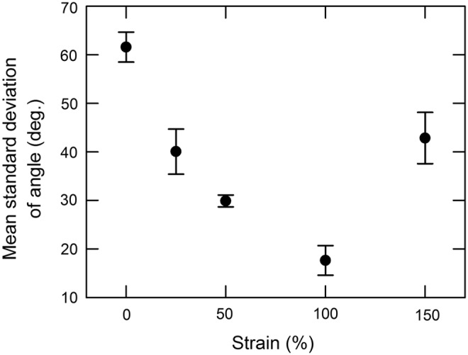
Influence of the strain on the alignment of collagen fibrils. Mean standard deviations (SDs) were obtained from six AFM images (64 square frames/images). Error bars correspond to the SDs of the six individual SDs taken from the six images.
Cell compatibility, alignment, and division
Cell compatibility, morphology, and alignment onto both nonstretched and stretched films were investigated using three types of cells: rat astrocytes42 as well as human and murine fibroblasts.43,44
Primary rat astrocytes
Primary astrocytes from rat, the most abundant cells in the brain, play a major role in the repair and scarring processes of the brain and spinal cord.42,45 It was suggested that alignment of these cells promotes the process.45 These cells adhere and spread well on S0, with their characteristic shape (Fig. 3A, B), as well as on S100 films where their shape is remarkably elongated (Fig. 3D, E). The distribution of the nucleus major axis angle of the astrocytes growing on S100 films peaks at about 0° with an SD of 32° (Fig. 3F), which contrasts with the uniform distribution (SD=53°) observed on S0 films (Fig. 3C). These results emphasize the fact that cells perceive the stretching through the alignment of the COL fibrils.
FIG. 3.

Fluorescence microscopy images of astrocytes cultured for 5 days on S0 and S100 films (A, B and D, E, respectively). Cells were stained for DAPI (blue nuclear dye) and vinculin (green dye). Distribution of the astrocyte nucleus angles on S0 and S100 films (C, F, respectively) (20 cells per condition). (A, B) The reference axis is parallel to the lower edge of the picture. (D, E) Arrows indicate the direction of stretching. Color images available online at www.liebertpub.com/tec
Human gingival fibroblasts
HGFs are the major constituents of gingival tissue and are therefore commonly evaluated for their potential use in craniofacial and dental tissue engineering.46 HGFs adhere and spread well onto both S0 and S100 films and align along the stretching direction on an S100 film (data not shown). To confirm this observation, the angles formed by the HGF nucleus major axis with respect to the stretching direction were measured on both nonstretched and 100% stretched films. As in the former example, the SD of the nucleus angle on S100 films (13°) is strongly reduced with respect to the SD on S0 films (56°). This observation confirms that HGFs align along the stretching direction and, hence, along the COL fibrils in a long range order on S100 films.
NIH 3T3 murine fibroblasts
NIH 3T3 murine fibroblasts, seeded on both S0 and S100 films, adhere, spread, and proliferate after 5 days of incubation (Fig. 4A, B and D, E, respectively). Focal contact visualization through vinculin labeling emphasizes these observations. On S0 films, they do not have any preferential orientation, whereas on S100 films, they exhibit a nearly uniaxial orientation, as observed on a microgrooved topography.44 Changes concern also the shape of the cells. On S0 films, cells spread out in an isotropic manner (often triangle-like shape), whereas on S100 films, cells stretch in spindle-like shapes and align along the stretching direction, which dictates that of the COL fibrils. Quantification of cell alignment was performed by determining the distribution of the angles of the major axis of the elliptical nuclei with respect to the stretching direction. The SD of the nucleus angle corresponding to S0 films is 52° (Fig. 4C), whereas that corresponding to S100 films drops to 22° and the distribution peaks in the vicinity of 0° (Fig. 4F).
FIG. 4.

Morphology of NIH 3T3 fibroblasts after 5 days of culture on S0 and S100 films observed with a fluorescence microscope at 10×(A, D, respectively) or 60×(B, E, respectively) with vinculin staining in green and DNA in blue (DAPI). (C, F) Distribution of the angle made by the longest axis of the 3T3 fibroblast nucleus with respect to a reference axis on S0 and S100 (100 cells/condition). (A, B) The reference axis is parallel to the lower edge of the picture. (D, E) Arrows indicate the direction of stretching. Color images available online at www.liebertpub.com/tec
The NIH 3T3 fibroblast alignment was further quantified by determining the distribution of the angle formed by the elliptic nucleus major axis and the stretching direction, as a function of the strain. One hundred cells were analyzed for each of the strains ɛ=0, 25, 50, 100, and 150%. The largest SD of the nucleus angle of 52° is obtained on S0 films, whereas the smallest (22°) on S100 films (Fig. 5). At ɛ=150%, cells do not align well because the integrity of the S150 films is altered, as mentioned above. These results indicate that the higher the strain, the better the alignment of the cells along the COL fibrils, until ɛ=100% is reached.
FIG. 5.
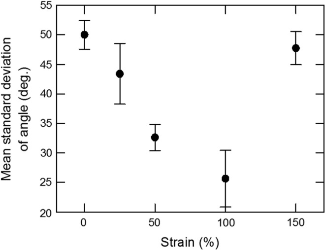
Influence of the strain on the alignment of the nucleus major axis of NIH 3T3 fibroblasts. SDs were obtained from 4×25 nuclei/condition observed by fluorescence microscopy. SDs, standard deviations.
Figures 6A and D show NIH 3T3 fibroblasts at high magnification. Focal contacts (green fluorescence for vinculin), involved in adhesion, migration, and proliferation processes, are randomly oriented on S0 films (Fig. 6A), but aligned along the stretching direction, and hence along the oriented COL fibrils on S100 films (Fig. 6D). The alignment of COL fibrils, which affects adhesion geometry, also leads to mitotic spindle orientation.47 Cells exhibit statistically uniform spindle and cell division orientation on S0 films (Fig. 6B) with an SD of the angle of 53° (Fig. 6C). On the contrary, on S100 films (Fig. 6E), the SD of the cell division angle drops to 29° and the distribution is concentrated around 0° (Fig. 6F) showing that mitotic spindles and cell divisions turn preferentially along the stretching direction which, in turn, induces the COL fibril orientation.
FIG. 6.

Fluorescence microscopy images of NIH 3T3 fibroblasts after 5-day culture on S0 and S100 films (A, D, respectively). Nuclei were stained with DAPI (blue dye) and focal contacts with anti-vinculin (green dye). Fluorescence microscopy images of the nuclei of NIH 3T3 fibroblasts cultured for 5 days on S0 and S100 films (B, E, respectively). The lines mark the orientation of cell divisions. Distribution of the angle formed by the cell division direction and the reference axis on S0 and S100 films (C, F, respectively). (A, B) The reference axis is parallel to the lower edge of the picture. (D, E) Arrows indicate the direction of stretching. Color images available online at www.liebertpub.com/tec
Self-standing COL/ALG membranes
The films described above are built on PDMS substrates that were mechanically stretched. To use these coatings in vivo for tissue engineering purposes, the PDMS substrates should be maintained in a stretched state without the mechanical device present in situ. To overcome this issue, the films need to be substrate free, while preserving their characteristics. To this end, the films, prepared on PDMS substrates (60 pairs of deposits), were first stretched and cross-linked, then dried (thickness about 1 μm), and finally peeled off from these substrates.
We observed that before peeling off, the collagen fibrils were aligned parallel to the stretch direction as they were in the 15-deposit film described above. This indicates that the film thickness has no influence on the alignment of COL fibrils within the domain investigated. After peeling off, the alignment of the collagen fibrils was preserved as observed by AFM (data not shown). NIH 3T3 fibroblasts were seeded on those peeled off membranes to test whether they could induce alignment of cells. SEM micrographs (Fig. 7A, D), corresponding, respectively, to nonstretched S0 and stretched S100 films, show the fibrillar structures of peeled off membranes deposited onto a glass slide. In Figure 7A, collagen fibrils from S0 membranes are uniformly distributed all over the surface, while in Figure 7D, the topography of the S100 peeled off membrane exhibits aligned fibrils. Thus, collagen fibrils remain oriented in the stretching direction. Figures 7B and E depict fluorescence microscopy images of cells cultured 5 days on, respectively, S0 and S100 COL/ALG peeled off membranes deposited onto glass slides. Cells grown on aligned membranes are well aligned along the collagen fibrils as indicated by the distribution of the nucleus angle (Fig. 7F), which contrasts with its nonstretched counterpart (Fig. 7C). This indicates that the aligned structure of the films is not altered during the peeling and redeposition steps.
FIG. 7.

SEM images of S0 (A) and S100 (D) COL/ALG membranes (60 pairs of layers) peeled off from polydimethylsiloxane (PDMS) substrates and deposited onto glass slides. Fluorescence microscopy images of NIH 3T3 fibroblasts cultured for 5 days on S0 (B) and S100 (E) membranes. Cells were stained after 5 days of incubation with DAPI (blue) and vinculin (green). Distribution of the nucleus angle: (C) corresponds to image (B) and (F) to image (E). (A, B) The reference axis is parallel to the lower edge of the picture. (D, E) Arrows indicate the direction of stretching. Color images available online at www.liebertpub.com/tec
These results demonstrate that these COL-based membranes may be suitable for application in biomedical fields, everywhere the regeneration of human tissues has to be oriented.15 For instance, engineered neural tissue containing aligned glial cells that support and guide neural regeneration has already be explored.48 In the perspective of the regeneration of the lost periodontal tissues where the periodontal ligament contains an organized structure of collagen fibers,15 the self-standing membranes, even of modest area, might provide the desirable controlled alignment of the cells. Nonetheless, in the case when larger membrane areas are required, as for the repair of tendons, our membrane production technique, notably as to the peeling off, should still be improved.
Conclusion
The collagen-based multilayer coatings developed here favor cell adhesion and proliferation. The mechanoresponsive features of the fibrillar structure of the COL/ALG films were demonstrated in the present study. The randomly distributed fibrils of the nonstretched multilayer become aligned as the coating is stretched. For the first time, we demonstrated that stretching of COL/ALG-coated PDMS substrates appears to be a convenient way to produce surfaces with aligned collagen fibrils. Interestingly, the degree of alignment of the fibrils can be tuned simply by changing the strain of the COL/ALG film. Moreover, the aligned COL/ALG coatings influence cell morphology and guide the cell division. Focal contacts, located at the ends of the elongated cells, appear to preferentially align along the COL fibrils. Furthermore, stress fibers extend parallel to the underlying collagen fibers. These findings indicate the existence of strong mechanical links between cells and the collagen of the outer layer of the film. They are similar to those reported for U2OS osteosarcoma cells deposited on a thick collagen matrix submitted to a cyclic stretch.32
Since these COL/ALG coatings can be peeled off from their substrates, they may offer substrates with controlled organization ranging from random to aligned fibrils suitable for tissue engineering strategies in the field of regenerative medicine.
Acknowledgments
One of us (C.C.) acknowledges the Faculté de Chirurgie Dentaire of Strasbourg for financial support. We are indebted to F.W. Pfrieger (Centre National de la Recherche Scientifique, UPR 3212, Université de Strasbourg) who kindly provided primary rat astrocytes. We also thank K. Benmlih for machining the stretching devices. We acknowledge the Région Alsace and the Pôle Matériaux et Nanosciences d'Alsace for financial contribution.
Disclosure Statement
No competing financial interests exist.
References
- 1.Kopecek J. Hydrogel biomaterials: a smart future? Biomaterials 28, 5185, 2007 [DOI] [PMC free article] [PubMed] [Google Scholar]
- 2.Slaughter B.V., Khurshid S.S., Fisher O.Z., Khademhosseini A., and Peppas N.A. Hydrogels in regenerative medicine. Adv Mater 21, 3307, 2009 [DOI] [PMC free article] [PubMed] [Google Scholar]
- 3.Glowacki J., and Mizuno S. Collagen scaffolds for tissue engineering. Biopolymers 89, 338, 2008 [DOI] [PubMed] [Google Scholar]
- 4.Oh H.H., Ko Y.-G., Lu H., Kawazoe N., and Chen G. Preparation of porous collagen scaffolds with micropatterned structures. Adv Mater 24, 4311, 2012 [DOI] [PubMed] [Google Scholar]
- 5.Decher G. Fuzzy nanoassemblies: toward layered polymeric multicomposites. Science 277, 1232, 1997 [Google Scholar]
- 6.Tang Z.Y., Wang Y., Podsiadlo P., and Kotov N.A. Biomedical applications of layer-by-layer assembly: from biomimetics to tissue engineering. Adv Mater 18, 3203, 2006 [Google Scholar]
- 7.Shah N.J., Hyder M.N., Moskowitz J.S., Quadir M.A., Morton S.W., Seeherman H.J., Padera R.F., Spector M., and Hammond P.T. Surface-mediated bone tissue morphogenesis from tunable nanolayered implant coatings. Sci Transl Med 5, 191ra83, 2013 [DOI] [PMC free article] [PubMed] [Google Scholar]
- 8.Monteiro I.P., Shukla A., Marques A.P., Reis R.L., and Hammond P.T. Spray-assisted layer-by-layer assembly on hyaluronic acid scaffolds for skin tissue engineering. J Biomed Mater Res A 103, 330, 2015 [DOI] [PubMed] [Google Scholar]
- 9.Johansson J.Å., Halthur T., Herranen M., Söderberg L., Elofsson U., and Hilborn J. Build-up of collagen and hyaluronic acid polyelectrolyte multilayers. Biomacromolecules 6, 1353, 2005 [DOI] [PubMed] [Google Scholar]
- 10.Mhanna R.F., Vörös J., and Zenobi-Wong M. Layer-by-layer films made from extracellular matrix macromolecules on silicone substrates. Biomacromolecules 12, 609, 2011 [DOI] [PubMed] [Google Scholar]
- 11.Grant G.S., Koktysh D., Yun B., Matts R., and Kotov N. Layer-by-layer assembly of collagen thin films: controlled thickness and biocompatibility. Biomed Microdevices 3, 301, 2001 [Google Scholar]
- 12.Chaubaroux C., Vrana E., Debry C., Schaaf P., Senger B., Voegel J.-C., Haikel Y., Ringwald C., Hemmerlé J., Lavalle P., and Boulmedais F. Collagen-based fibrillar multilayer films cross-linked by a natural agent. Biomacromolecules 13, 2128, 2012 [DOI] [PubMed] [Google Scholar]
- 13.Zhang J., Senger B., Vautier D., Picart C., Schaaf P., Voegel J.-C., and Lavalle P. Natural polyelectrolyte films based on layer-by layer deposition of collagen and hyaluronic acid. Biomaterials 26, 3353, 2005 [DOI] [PubMed] [Google Scholar]
- 14.Li W., Zhao P., Lin C., Wen X., Katsanevakis E., Decher G., Félix O., and Liu Y. Natural polyelectrolyte self-assembled multilayers based on collagen and alginate: stability and cytocompatibility. Biomacromolecules 14, 2647, 2013 [DOI] [PubMed] [Google Scholar]
- 15.Shang S., Yang F., Cheng X., Walboomers X.F., and Jansen J.A. The effect of electrospun fibre alignment on the behaviour of rat periodontal ligament cells. Eur Cells Mater 19, 180, 2010 [DOI] [PubMed] [Google Scholar]
- 16.Builles N., Janin-Manificat H., Malbouyres M., Justin V., Rovère M.R., Pellegrini G., Torbet J., Hulmes D.J.S., Burillon C., Damour O., and Ruggiero F. Use of magnetically oriented orthogonal collagen scaffolds for hemi-corneal reconstruction and regeneration. Biomaterials 31, 8313, 2010 [DOI] [PubMed] [Google Scholar]
- 17.Kaufman L.J., and Guo C. Flow and magnetic field induced collagen alignment. Biomaterials 28, 1105, 2007 [DOI] [PubMed] [Google Scholar]
- 18.Dubey N., Letourneau P.C., and Tranquillo R.T. Neuronal contact guidance in magnetically aligned fibrin gels: effect of variation in gel mechano-structural properties. Biomaterials 22, 1065, 2001 [DOI] [PubMed] [Google Scholar]
- 19.Kotani H., Iwasaka M., Ueno S., and Curtis A. Magnetic orientation of collagen and bone mixture. J Appl Phys 87, 6191, 2000 [Google Scholar]
- 20.Yang F., Murugan R., Wang S., and Ramakrishna S. Electrospinning of nano/micro scale poly(l-lactic acid) aligned fibers and their potential in neural tissue engineering. Biomaterials 26, 2603, 2005 [DOI] [PubMed] [Google Scholar]
- 21.Baker S.C., Atkin N., Gunning P.A., Granville N., Wilson K., Wilson D., and Southgate J. Characterisation of electrospun polystyrene scaffolds for three-dimensional in vitro biological studies. Biomaterials 27, 3136, 2006 [DOI] [PubMed] [Google Scholar]
- 22.Liu Y.Q., Zhang X.P., Xia Y.N., and Yang H. Magnetic-field-assisted electrospinning of aligned straight and wavy polymeric nanofibers. Adv Mater 22, 2454, 2010 [DOI] [PMC free article] [PubMed] [Google Scholar]
- 23.Huang N.F., Patel S., Thakar R.G., Wu J., Hsiao B.S., Chu B., Lee R.J., and Li S. Myotube assembly on nanofibrous and micropatterned polymers. Nano Lett 6, 537, 2006 [DOI] [PubMed] [Google Scholar]
- 24.Subramony S.D., Dargis B.R., Castillo M., Azeloglu E.U., Tracey M.S., Su A., and Lu H.H. The guidance of stem cell differentiation by substrate alignment and mechanical stimulation. Biomaterials 34, 1942, 2013 [DOI] [PMC free article] [PubMed] [Google Scholar]
- 25.Vernon R.B., Gooden M.D., Lara S.L., and Wight T.N. Microgrooved fibrillar collagen membranes as scaffolds for cell support and alignment. Biomaterials 26, 3131, 2005 [DOI] [PubMed] [Google Scholar]
- 26.Chen A., Lieu D.K., Freschauf L., Lew V., Sharma H., Wang J.X., Nguyen D., Karakikes I., Hajjar R.J., Gopinathan A., Botvinick E., Fowlkes C.C., Li R.A., and Khine M. Shrink-film configurable multiscale wrinkles for functional alignment of human embryonic stem cells and their cardiac derivatives. Adv Mater 23, 5785, 2011 [DOI] [PubMed] [Google Scholar]
- 27.Guvendiren M., and Burdick J.A. Stem cell response to spatially and temporarilly displayed and reversible surface topography. Adv Healthc Mater 2, 155, 2013 [DOI] [PubMed] [Google Scholar]
- 28.Lee P., Lin R., Moon J., and Lee L.P. Microfluidic alignment of collagen fibers for in vitro cell culture. Biomed Microdevices 8, 35, 2006 [DOI] [PubMed] [Google Scholar]
- 29.Tanaka Y., Baba K., Duncan T.J., Kubota A., Asahi T., Quantock A.J., Yamato M., Okano T., and Nishida K. Transparent, tough collagen laminates prepared by oriented flow casting, multi-cyclic vitrification and chemical cross-linking. Biomaterials 32, 3358, 2011 [DOI] [PubMed] [Google Scholar]
- 30.Teixeira A.I., Abrams G.A., Bertics P.J., Murphy C.J., and Nealey P.F. Epithelial contact guidance on well-defined micro- and nanostructured substrates. J Cell Sci 116, 1881, 2003 [DOI] [PMC free article] [PubMed] [Google Scholar]
- 31.Schnell E., Klinkhammer K., Balzer S., Brook G., Klee D., Dalton P., and Mey J. Guidance of glial cell migration and axonal growth on electrospun nanofibers of poly-epsilon-caprolactone and a collagen/poly-epsilon-caprolactone blend. Biomaterials 28, 3012, 2007 [DOI] [PubMed] [Google Scholar]
- 32.Tondon A., and Kaunas R. The direction of stretch-induced cell and stress fiber orientation depends on collagen matrix stress. PLoS One 9, e89592, 2014 [DOI] [PMC free article] [PubMed] [Google Scholar]
- 33.Heo S.-J., Nerurkar N.L., Baker B.M., Shin J.-W., Elliott D.M., and Mauck R.L. Fiber stretch and reorientation modulates mesenchymal stem cell morphology and fibrous gene expression on oriented nanofibrous microenvironments. Ann Biomed Eng 39, 2780, 2011 [DOI] [PMC free article] [PubMed] [Google Scholar]
- 34.Zeugolis D.I., Khew S.T., Yew E.S.Y., Ekaputra A.K., Tong Y.W., Yung L.Y.L., Hutmacher D.W., Sheppard C., and Raghunath M. Electro-spinning of pure collagen nano-fibres—just an expensive way to make gelatin? Biomaterials 29, 2293, 2008 [DOI] [PubMed] [Google Scholar]
- 35.Weiss P. In vitro experiments on the factors determining the course of the outgrowing nerve fiber. J Exp Zool 68, 393, 1934 [Google Scholar]
- 36.Sutherland J., Denyer M., and Britland S. Contact guidance in human dermal fibroblasts is modulated by population pressure. J Anat 206, 581, 2005 [DOI] [PMC free article] [PubMed] [Google Scholar]
- 37.Voge C.M., Kariolos M., MacDonald R.A., and Stegemann J.P. Directional conductivity in SWNT-collagen-fibrin composite biomaterials through strain-induced matrix alignment. J Biomed Mater Res A 86, 269, 2008 [DOI] [PubMed] [Google Scholar]
- 38.Vader D., Kabla A., Weitz D., and Mahadevan L. Strain-induced alignment in collagen gels. PLoS One 4, e5902, 2009 [DOI] [PMC free article] [PubMed] [Google Scholar]
- 39.Mertz D., Vogt C., Hemmerlé J., Mutterer J., Ball V., Voegel J.-C., Schaaf P., and Lavalle P. Mechanotransductive surfaces for reversible biocatalysis activation. Nat Mater 8, 731, 2009 [DOI] [PubMed] [Google Scholar]
- 40.Rezakhaniha R., Agianniotis A., Schrauwen J.T.C., Griffa A., Sage D., Bouten C.V.C., Vosse F.N., Unser M., and Stergiopulos N. Experimental investigation of collagen waviness and orientation in the arterial adventitia using confocal laser scanning microscopy. Biomech Model Mechanobiol 11, 461, 2012 [DOI] [PubMed] [Google Scholar]
- 41.Ruoslahti E., and Pierschbacher M.D. New perspectives in cell adhesion: RGD and integrins. Science 238, 491, 1987 [DOI] [PubMed] [Google Scholar]
- 42.Renault-Mihara F., Okada S., Shibata S., Nakamura M., Toyama Y., and Okano H. Spinal cord injury: emerging beneficial role of reactive astrocytes' migration. Int J Biochem Cell Biol 40, 1649, 2008 [DOI] [PubMed] [Google Scholar]
- 43.Loesberg W.A., te Riet J., van Delft F.C.M.J.M., Schön P., Figdor C.G., Speller S., van Loon J.J.W.A., Walboomers X.F., and Jansen J.A. The threshold at which substrate nanogroove dimensions may influence fibroblast alignment and adhesion. Biomaterials 28, 3944, 2007 [DOI] [PubMed] [Google Scholar]
- 44.Dalby M.J., Riehle M.O., Yarwood S.J., Wilkinson C.D.W., and Curtis A.S.G. Nucleus alignment and cell signaling in fibroblasts: response to a micro-grooved topography. Exp Cell Res 284, 272, 2003 [DOI] [PubMed] [Google Scholar]
- 45.East E., de Oliveira D.B., Golding J.P., and Phillips J.B. Alignment of astrocytes increases neuronal growth in three-dimensional collagen gels and is maintained following plastic compression to form a spinal cord repair conduit. Tissue Eng Part A 16, 3173, 2010 [DOI] [PMC free article] [PubMed] [Google Scholar]
- 46.Lee I.-K., Lee M.-J., and Jang H.-S. The interrelationship between human gingival fibroblast differentiation and cultivating time. Tissue Eng Regen Med 10, 60, 2013 [Google Scholar]
- 47.Wang X., Ohlin C.A., Lu Q., and Hu J. Cell directional migration and oriented division on three-dimensional laser-induced periodic surface structures on polystyrene. Biomaterials 29, 2049, 2008 [DOI] [PubMed] [Google Scholar]
- 48.Lietz M., Dreesmann L., Hoss M., Oberhoffner S., and Schlosshauer B. Neuro tissue engineering of glial nerve guides and the impact of different cell types. Biomaterials 27, 1425, 2006 [DOI] [PubMed] [Google Scholar]