

Abstract
Neural networks along the spinal cord contribute substantially to generating locomotion behaviours in humans and other legged animals. However, the neural circuitry involved in this spinal control remains unclear. We here propose a specific circuitry that emphasizes feedback integration over central pattern generation. The circuitry is based on neurophysiologically plausible muscle-reflex pathways that are organized in 10 spinal modules realizing limb functions essential to legged systems in stance and swing. These modules are combined with a supraspinal control layer that adjusts the desired foot placements and selects the leg that is to transition into swing control during double support. Using physics-based simulation, we test the proposed circuitry in a neuromuscular human model that includes neural transmission delays, musculotendon dynamics and compliant foot–ground contacts. We find that the control network is sufficient to compose steady and transitional 3-D locomotion behaviours including walking and running, acceleration and deceleration, slope and stair negotiation, turning, and deliberate obstacle avoidance. The results suggest feedback integration to be functionally more important than central pattern generation in human locomotion across behaviours. In addition, the proposed control architecture may serve as a guide in the search for the neurophysiological origin and circuitry of spinal control in humans.
Key points
It is often assumed that central pattern generators, which generate rhythmic patterns without rhythmic inputs, play a key role in the spinal control of human locomotion.
We propose a neural control model in which the spinal control generates muscle stimulations mainly through integrated reflex pathways with no central pattern generator.
Using a physics-based neuromuscular human model, we show that this control network is sufficient to compose steady and transitional 3-D locomotion behaviours, including walking and running, acceleration and deceleration, slope and stair negotiation, turning, and deliberate obstacle avoidance.
The results suggest feedback integration to be functionally more important than central pattern generation in human locomotion across behaviours.
In addition, the proposed control architecture may serve as a guide in the search for the neurophysiological origin and circuitry of spinal control in humans.
Introduction
Humans show a range of locomotion behaviours from walking and running to stair and slope negotiation to turning and deliberate obstacle avoidance. Experimental evidence has established that neural networks along the spinal cord contribute substantially to generating these behaviours in humans and other legged animals (Grillner, 2006; Bizzi et al. 2008; Gerasimenko et al. 2008; Harkema et al. 2011); however, the specific neural circuitry involved in this spinal control remains unclear. The current main ideas about what this circuitry is composed of revolve around central pattern generators (CPGs) and muscle synergies. CPGs are mutually inhibiting neural circuits in the spinal cord (Guertin, 2009) that can produce rhythmic patterns of neural activity without rhythmic inputs (Ijspeert, 2008). Animal experiments have confirmed the existence of CPG networks in invertebrates (Orlovsky et al. 1999). They have also shown mammals performing locomotion-like rhythmic limb movements in the absence of both supraspinal and peripheral inputs (Brown, 1911; Grillner & Zangger, 1979; Rossignol et al. 2008), although their CPG network remains a black box (Guertin, 2009). Muscle synergies can be viewed as a generalization of CPGs, providing the flexibility to compose more than just rhythmic behaviour (Ijspeert, 2008). They are proposed control modules located in the spinal cord that activate a group of muscles in a fixed balance (Bizzi et al. 2008; Tresch & Jarc, 2009). Using computational factorization algorithms, several research groups have shown that only a handful of synergies would be required to explain the muscle activities found in different animals and humans for locomotion behaviours from swimming to balancing to walking (Tresch et al. 1999; Ivanenko et al. 2004; Cheung et al. 2005; Torres-Oviedo & Ting, 2007; Dominici et al. 2011). Recent physiological evidence supports the existence of synergies (Bizzi & Cheung, 2013), but similar to CPGs, the neural origin and circuitry of synergies remains debated (Tresch & Jarc, 2009; Kutch & Valero-Cuevas, 2012).
Using a physics-based neuromuscular human model, we here propose a specific neural circuitry to compose a range of locomotion behaviours. Most previous human model studies that propose a neural control architecture emphasize spinal pattern generation (Taga et al. 1991; Taga, 1998; Ogihara & Yamazaki, 2001; Hase et al. 2003; Paul et al. 2005; Kim et al. 2011). In these models, mutually inhibiting neurons (Matsuoka, 1985) are combined to a number of CPGs that generate spinal, oscillatory outputs at each joint of the lower limbs. Although the activity of the CPG models is altered in timing and amplitude by feedback from muscle, skin and joint sensors, as well as from the vestibular system (Hase et al. 2003; Paul et al. 2005; Kim et al. 2011), the functional importance of these sensory feedback pathways to generating locomotion behaviours is not explicitly addressed.
Here we show that sensory feedback integration, without spinal pattern generation, is sufficient to generate human locomotion across behaviours. We develop a three-dimensional human neuromuscular model that generalizes the muscle reflex circuitry of a previous sagittal plane model (Geyer & Herr, 2010). In particular, we replace the previous model's swing phase reflexes with a functionally more relevant reflex circuitry of swing leg placement (Desai & Geyer, 2012, 2013; Song et al. 2013), and integrate muscle reflexes for hip abduction and adduction (Song & Geyer, 2013). The resulting control is organized in 10, mainly independent, spinal feedback modules that realize limb functions essential to legged locomotion. In addition, we incorporate a higher layer, longer latency control that can alter some of the reflex gains. This supraspinal control adjusts the desired foot placements (Kajita et al. 2001; Yin et al. 2007) and selects the leg that is to transition into swing control during double support. Using computer optimization of the model's control parameters, we find that the control network is sufficient to compose steady and transitional 3-D locomotion behaviours including walking and running, acceleration and deceleration, slope and stair negotiation, turning, and deliberate obstacle avoidance. (Video S1 in the online Supporting information demonstrates these behaviours.) The results support the hypothesis that feedback integration is functionally more important than central pattern generation in human locomotion across behaviours. In addition, the proposed control architecture may serve as a guide in the search for the neurophysiological origin and circuitry of spinal control in humans.
Methods
We develop a human locomotion model which extends a previous sagittal plane model of the human neuromuscular system (Geyer & Herr, 2010) to a three-dimensional version with additional muscles and foot geometry (Fig.1) as well as with a neural control circuitry organized in 10 functional, spinal reflex modules (Fig.3) and a higher layer adjusting the foot placement (Fig.2).
Figure 1. 3-D neuromuscular human model walking over rough ground with height changes up to ±10 cm (snapshots every 600 ms).
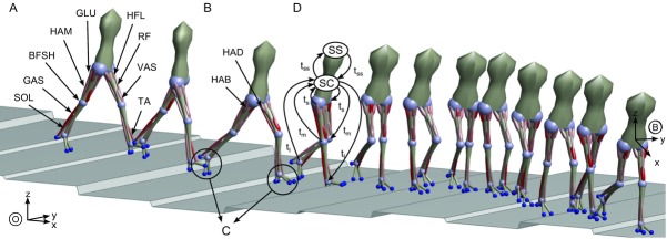
The model consists of 7 segments connected by 8 revolute joints and actuated by 11 muscles per leg. A, 9 muscles actuate the sagittal plane joints at the hip, knee and ankle. B, the hip is further actuated in the lateral plane by 2 muscles. C, each foot has 4 contact points generating continuous ground interaction forces when engaged. D, the neural circuitry of the spinal cord (SC) controlling the muscles is organized into 10 functional modules that are subject to long (tl), medium (tm), and short transmission delays (ts). The communication between the spinal cord and the supraspinal system (SS) adjusting the foot placement is equally delayed (tss).
Figure 3. Reflex modules of the spinal control layer.

A, 10 reflex modules realize with decentralized feedback key functions of legged systems including compliant behaviour and trunk balance in stance (M1 to M5) and ground clearance and leg placement in swing (M5 to M10). B, schematic contribution of the modules to each muscle's stimulation throughout the gait cycle. The dotted portions indicate modules that are inhibited or excited during double support in proportion to the load Fc on the contralateral leg when transitioning from stance control to swing control. Sw1 to Sw4 trigger events within swing control (see text for details).
Figure 2. Neural control organization.
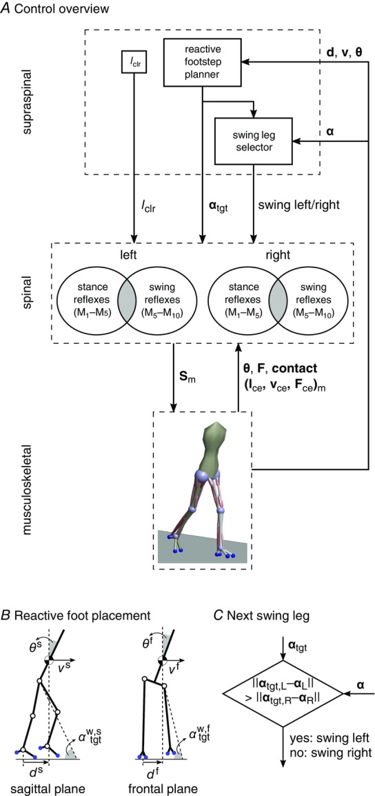
A, the control is organized in spinal and supraspinal layers. The spinal layer consists of 10 reflex modules, M1 to M10, for each leg which are active in stance or swing. The supraspinal layer adjusts the desired foot placements (αtgt) and the desired minimum swing leg length (lclr), and selects which leg should transition into swing control during double support. B, desired foot placement is calculated as target leg angles  and
and  for sagittal (s) and frontal (f) plane motions based on the velocity vs, f of the COM and its distance to the stance leg ankle, ds, f. C, in double support, swing control is initiated for the leg whose angle α is farther from the target.
Musculoskeletal mechanics
The model represents a 180 cm tall person weighing 80 kg with seven segments connected by eight internal degrees of freedom (DOFs) and actuated by 22 muscle tendon units (MTUs) (Fig.1). The segments include the trunk describing the whole upper body and the thighs, shanks and feet with geometric and inertial properties estimated from human data (Table 2, Appendix A). Revolute joints connect the segments with two DOFs at the hips (pitch and roll) and one DOF at the knees and ankles (pitch only). Each leg is actuated by 11 Hill-type MTUs. Nine MTUs actuate the three sagittal plane pitch joints (Fig.1A) modelling the lumped hip flexors (HFL), the glutei (GLU), the hamstrings (HAM), the rectus femoris (RF), the vastii (VAS), the short head of the biceps femoris (BFSH), the gastrocnemius (GAS), the soleus (SOL) and the tibialis anterior (TA). The remaining two MTUs, modelling the hip abductors (HAB) and adductors (HAD), actuate the hip roll joints (Fig.1B).
Muscle tendon units
The MTU model is detailed in Geyer & Herr (2010). Each MTU consists of a contractile element (CE) and series (SE) and parallel elasticities (PE). The MTU force Fm is calculated solving 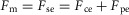 , where the active CE exerts a force
  with Fmax being the maximum isometric force,
  and
and  being the force–length and force–velocity relationships, and Am being the muscle activation. Muscle activation is generated by a first-order delay from muscle stimulation Sm, which is the output of the spinal control modules. The physiological differences between the MTUs are captured with four parameters including the maximum isometric force Fmax, the maximum contraction velocity vmax of the CE, the optimal CE length lopt, and the SE slack length lslack. For each MTU, these properties are estimated from human data (Table 3, Appendix A).
Instantaneous moment arms
A muscle force Fm generates a torque  at the joints the muscle spans, where
  is the instantaneous moment arm. All moment arms are matched to reported physiological data (Visser et al. 1990; Arnold et al. 2010; Geyer & Herr, 2010; McCullough et al. 2011), using either a constant value or a scaled cosine relationship (Table 4, Appendix A).
Foot–ground contacts
The musculoskeletal system interacts with the ground via four compliant contact models on each foot (Fig.1C). The contact points are located at the edges of the foot segment in the sagittal plane representing the heel as well as the ball and toe region of a human foot. In the frontal plane, the contact points are 10 cm apart at the ball and 5 cm apart at the heel. If a contact point touches the ground, ground reaction forces (GRFs) act on the foot segment at that point. The normal GRF is calculated as non-linear spring–damper force. The tangential GRF acts in either static or sliding mode, where static friction is modelled as non-linear spring–damper force, and sliding friction is proportional to the normal GRF (for details, see Song & Geyer, 2013).
Neural control circuitry
The neural circuitry of the human model is organized into spinal reflex modules combined with a supraspinal layer. The spinal modules realize individual limb functions essential to legged systems with decentralized feedback control. The supraspinal layer adjusts the desired foot placements and modulates some of the spinal reflexes (Fig.2A). The inputs to this hierarchical control structure include the muscle states such as the length, velocity or force of the contractile elements, joint states such as knee angle and angular velocity, the ground contact information, as well as the trunk's centre of mass (COM) position and velocity relative to the stance foot, and the leg angles and the global trunk lean. The outputs are the muscle stimulations  of the left (L) and right leg (R) generated by the spinal reflex modules.
Reflex control modules
Each leg's muscles are controlled by 10 reflex modules M1 to M10 based on their functional role in stance (M1 to M5) or swing (M5 to M10) (Fig.2A). In addition, if a leg is selected by the supraspinal layer to switch from stance control to swing control during the transitional double support phase, some of the stance control modules can be inhibited (M1 and M2) and some of the swing control modules can be excited (M6 and M7) in proportion to contralateral leg loading. For most muscles, the resulting net stimulation is generated by several control modules that can be active simultaneously. We summarize here the function of each module and describe their implementation in Appendix B.
The stance control is taken from Geyer & Herr (2010) with modifications for some modules and an extension for lateral trunk balance (Fig.3). The first key function of the stance control is to robustly generate compliant leg behaviour. Module M1 realizes compliant leg behaviour using positive force feedbacks (F+) of the leg extensors (GLU, VAS and SOL). As compliant behaviour of segmented legs is prone to buckling (Seyfarth et al. 2001), M2 prevents knee hyperextension by positive force feedbacks of the biarticular knee flexors (HAM and GAS) throughout stance and by exciting the monoarticular knee flexor (BFSH) while reciprocally inhibiting the knee extensor (VAS) with muscle length feedbacks ( if the knee approaches hyperextension. The second key function of the stance control is to maintain trunk balance. M3 is the main module realizing this behaviour by activating the hip antagonists in the sagittal (HFL, GLU and HAM) and frontal planes (HAB and HAD) based on an assumed vestibular or visual feedback of the trunk pitch (θs) and roll (θf) in the world frame. (S+ in the M3 panel of Fig.3A indicates that HAM is co-stimulated in proportion to the stimulation of GLU.) The intensity of the M3 output is modulated by sensory feedback of the load Fi on the ipsilateral leg to prevent it from slipping due to exaggerated hip torques. In addition, the module M4 compensates for the moment induced on the trunk by the contralateral swing leg by co-stimulating the ipsilateral leg's antagonist hip muscles in the sagittal plane and agonist hip muscles in the frontal plane (S+).
The last spinal module active in stance control, M5, is also active in swing control and serves a dual purpose. It uses muscle length feedback (L+) of the ankle flexor (TA) to generate foot ground clearance in swing and to prevent ankle hyperextension in stance. In stance control, this length feedback is inhibited reciprocally by negative force feedback (F−) from the ankle extensor (SOL) to reduce unnecessary antagonistic activation.
The main part of the swing control composed of modules M6 to M10 is adapted from Desai & Geyer (2013) (Fig.3). Its key functions are to generate sufficient ground clearance and to robustly place the leg into target angles in the sagittal and frontal planes. The desired minimum leg length, lclr, for ground clearance and target angles 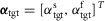 are provided to the spinal layer by supraspinal inputs (Fig.2A). Throughout swing, module M6 drives the hip muscles (HFL, GLU, HAB, and HAD) in proportion to the errors in leg angles
  to control swing leg placement. For the frontal plane, the error is provided as muscle length feedback (L−) from the hip abductor and adductor, HAB and HAD, interpreting the offset, loff, in the length feedback signal
  as a means to adjust the target angle via γ-motoneuron stimulation (not shown in Fig.3A). A similar length feedback (L−) of the biarticular muscles spanning the hip and knee, HAM and RF, provides an estimate of the leg angle error in the sagittal plane (shown in Fig.3A).
The remaining swing leg modules control the knee to achieve ground clearance and return to leg extension when approaching the target angle (Fig.3A). Module M7 uses velocity feedback from RF (estimating sagittal leg angular velocity  to the monoarticular knee flexor BFSH to ensure initial knee flexion. Module M8 uses length feedback of VAS (L+) to monitor leg length, again interpreting the length offset loff, VAS as the desired minimum leg length lclr which can be adjusted by γ-motoneuron activity. When VAS stretches past the offset (the leg shortens below lclr) (Sw1 in Fig.3B), M8 deactivates M7 and dampens the knee motion with positive velocity feedbacks (V+) of VAS on RF and of BFSH on itself, accounting for the fact that muscles can only pull. (BFSH is further modulated by feedback from RF to allow the knee to passively extend when αs approaches its target). The sagittal leg angle, αs, is monitored simultaneously with length feedbacks of HAM and RF. When αs as measured by HAM passes a threshold close to the target value
  (Sw2), M9 begins to use positive length feedback (L+) of HAM to decelerate the leg angular motion. At the same time, when αs passes this target as measured by RF (Sw3), M8 is deactivated. Finally, once the leg starts to retract (
 , detected by velocity feedback of HAM; Sw4), module M10 engages and uses positive length feedbacks (L+) of the hip muscles (GLU and HFL) and the knee extensor (VAS) to extend the leg (VAS) and hold it close to the targeted angle (GLU and HFL).
If a leg is selected by the supraspinal layer to switch from stance control to swing control during the double support phase, the outputs of modules M1 and M2 for the hip and knee muscles are inhibited by proportional feedback of the contralateral leg force Fc to terminate stance (shown as a factor  in Fig.3B). (M1 and M2 remain unmodified for the ankle muscles to provide ankle push off.) At the same time, M6 and M7 are proportionally excited by the same contralateral force to initiate swing. The modulation with Fc guarantees that the transition from stance to swing control occurs only if the body weight transfers to the contralateral leg.
Supraspinal control layer
The supraspinal control layer adjusts the desired foot placements in swing. It selects the leg that is to transition into swing control in double support and provides to the spinal cord layer the desired minimum leg length lclr for ground clearance and the desired foot placement in the form of target leg angles αtgt in the sagittal and frontal planes (Fig.2A). Several approaches have been proposed to compute desired foot placements for dynamic balance in 3-D walking and running (Raibert & Tello, 1986; Kajita et al. 2001; Yin et al. 2007; Wu & Geyer, 2013). We adapt the heuristic approach of Yin et al. (2007) due to its simplicity. For instance, the desired leg angle of the left leg (L) in the sagittal plane (s) is calculated as  , where
  is the angle that the sagittal hip-ankle line forms with the horizontal plane of the world frame w;
  ,
,  and
and  are positive constants; and
  and
and  are the time-delayed horizontal position and velocity of the COM relative to the ankle of the right foot (Fig.2B). Four different target angles are computed accounting for the sagittal and frontal planes of the left and right leg. The resulting target angle vector
  is sent to the spinal layer in body frame coordinates,
If the legs are in double support, the supraspinal layer additionally selects the leg whose control is to transition into swing based on the distance of the leg angles to their targets (Fig.2C). For each leg, the leg angle distance is cal-culated as  and the next swing leg is chosen to be the one whose angle distance is larger, as the other leg is better positioned to balance the trunk in stance. Both the swing leg selection and the target angle vector αtgt are updated continuously, allowing the supraspinal layer to react to disturbances throughout the gait cycle.
Neural transmission delays
All neural connections are time delayed to reflect physiological constraints on neural transmission speed (Meunier et al. 1990; Grey et al. 2001; Knikou & Rymer, 2002) (Fig.1D). The one-way delay between the supraspinal system and the spinal cord is set to  ms. The delays projecting between the spinal cord and the areas of the hip, knee and ankle are set to short, medium and long delays with
  ms,
ms,  ms, and
  ms. The total delay of a neural circuit results from the delays of its individual connections. For example, the delay of the positive force feedback of the ankle extensor SOL in module M1 is
  ms, and the delay of the positive velocity feedback from RF to BFSH in module M7 is
  ms.
ms.
Implementation and behaviour optimization
We implement the neuromuscular model in the MATLAB Simulink/SimMechanics environment (R2013a) with the ode15s solver (max. step size of 10 ms, relative and absolute error tolerance of 1 × 10⁻³ and 1 × 10⁻⁴, respectively) and optimize the control parameters with the covariance matrix adaptation evolution strategy (Hansen, 2006) to test the versatility of the proposed neural control circuitry in generating locomotion behaviours. The circuitry has 82 control parameters (7 for the reactive foot placement, 40 for stance reflexes, 31 for swing reflexes, and 4 for the modulation in the control transition). The simulation runs at about real time on a modern desktop computer, and a typical optimization run with a population size of 16 parameter individuals evolving over 400 generations takes about 1 day.
A successful optimization run required proper initial parameters as solutions can get stuck in local minima. For energy-efficient walking (see next paragraph), we hand-tuned the initial parameters based on our intuition about walking from similar models (Song & Geyer, 2012). During this hand-tuning process, which involved about 10 optimization runs, we encountered different solutions in local minima with substantially higher energy cost and largely different joint kinematics and kinetics. Once we had found a suitable initial parameter set, the optimization consistently converged to solutions with similar kinematics, kinetics and energetic costs. With this initial parameter set, single optimization runs were sufficient to find most of the other target behaviours. Exceptions were some of the more complex behaviours, for which we chained several optimization runs. This process used the result of one optimization in the next (for example, we used the solution for fast walking to find speed transitions from fast to slow walking), which could take up to 1 week to compute.
The cost function has a similar structure for all investigated behaviours. It consists of three parts,
| (1) |
with the first two parts encouraging the model not to fall down first (eqn (1)a, falling distance xfall) and then to achieve steady locomotion (eqn (1)b). The steadiness measure dsteady is the summed differences of the relative Cartesian positions of the segment edges at touchdown. Based on previous tests, the model is considered in steady locomotion if this sum is smaller than 10 cm for six consecutive steady steps (Song & Geyer, 2012). The last part (eqn (1)c) is task specific and encourages energy-efficient locomotion (energetic cost CE) at a target velocity  , where the frontal plane target speed
  , and vavg is the average velocity over the last six steady steps. The constant
  ensures eqn (1)a > (1)b > (1)c. The energetic cost is calculated as
  , where EM is the metabolic energy consumed by all muscles (Umberger et al. 2003), m is the body mass, and
 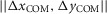 is the distance travelled in the horizontal plane. The values of vavg and CE are calculated over the last six consecutive steps of steady walking.
Results
We first confirm that the proposed reflex circuitry reproduces human walking behaviour (Figs 4 and 5), then explore the contributions of the individual control modules (Figs 5 and 6), and finally show the versatility of the reflex circuitry in generating other locomotion behaviours by supraspinal modulation (Fig.7).
Figure 4. Kinematics and dynamics for walking at 1.2 m s−1 in humans (grey traces) and the 3-D neuromuscular model (black traces) over a normalized gait cycle.
Stance lasts from 0% to about 60%. The panels show the roll, pitch and yaw of the trunk with respect to the world frame (A, compare Fig.1), the leg joint angles and torques (B), and the ground reaction forces in fore–aft (x), mediolateral (y), and vertical directions (z) (C). The grey areas (i–iv) highlight key differences between model and human data. Human data adapted from Rose et al. (2006) (angles), Eng & Winter (1995) (torques) and Damavandi et al. (2012) (GRFs). R, cross-correlation values (Wren et al. 2006).
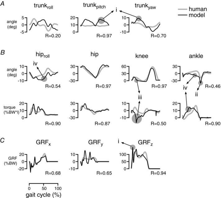
Figure 5. Comparison of muscle activations in normal walking.
A, human muscle activations for the 11 muscle groups of the model estimated from low-pass-filtered surface electromyograms (adapted from Perry & Burnfield, 2010). B, model-predicted muscle activations with coefficients of correlation (R) between model and human data. C, contributions of individual control modules Mi to the activation of selected muscles (S0, prestimulation contribution). Net activation in B is the sum of the contributions and saturated within 0% and 100%. Shaded backgrounds indicate stance phase with double supports in a darker hue. Compared muscles: (i) gluteus medius, (ii) adductor magnus, (iii) adductor longus, (iv) gluteus maximus, (v) semimembranosus, (vi) vastus lateralis. R, cross-correlation value.
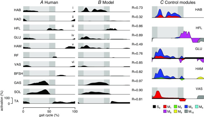
Figure 6. Peak contributions of spinal modules to individual muscle activations in steady (grey) and disturbed walking (black).
Control modules with peak increases of more than 20% are indicated in the grid.
Figure 7. Behaviour diversity.
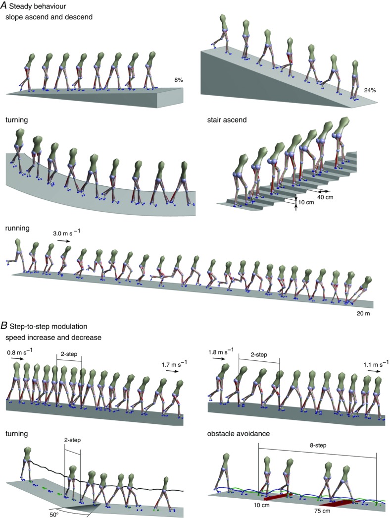
Snapshots of the human neuromuscular model during steady (A) and transitional behaviours (B) are shown.
Quality of walking behaviour
The reflex circuitry generates walking with overall human-like kinematics, dynamics and muscle activation patterns, although the energy optimization leads to a lower quality match than obtained in the previous work (Geyer & Herr, 2010). Figure4 shows the joint kinematics and dynamics and the GRFs obtained from optimizing the control parameters with the cost function (eqn (1)) for a normal human walking speed of 1.2 m s−1. Some differences to the human walking patterns are introduced by the simplified structure of the skeletal model. For instance, the reduction of the entire upper body to a rigid segment neglects soft, force-buffering structures in the human trunk and leads to higher impact forces and larger trunk motions after heel strike (Fig.4 (i)). Also, the lack of a toe segment results in more plantar flexion in late stance (ii). These differences (i and ii) have also been observed in the previous, planar model (Geyer & Herr, 2010). However, the energy optimization introduces additional differences. The model now tends to straighten the knee early in stance (iii), known to generate more energy-efficient solutions in gait optimization (Ackermann & van den Bogert, 2010; Umberger, 2010). The early straightening induces less dorsiflexion at the ankle and excessive roll at the hip (iv). Both differences (iii) and (iv) are not observed when the model is optimized to match the reference kinematics instead of minimizing the energetic cost (not shown).
With the exception of HAD, the correlation coefficients between predicted and observed activation patterns lie within the range found in human experiments (average R = 0.40–0.81 for inter-subject comparison, Wren et al. 2006) (Fig.5A and B). Compared to the previous planar model, the energy optimization slightly reduces the quality of the match for the ankle muscles (SOL, GAS and TA; R ≥ 0.80). On the other hand, the functionally improved spinal circuitry leads to a better match for the hip flexor (HFL) throughout the gait cycle (R = 0.86), now generates VAS activity in stance preparation at the end of swing, and captures the overall activation patterns of the added muscles BFSH and RF, although the onset of RF activity is late by about 10% of the gait cycle. The largest difference between predicted and observed activity occurs for the added hip adductors (HAD, R = 0.32), whose exclusive action on the hip roll DOF in the model probably over-simplifies the action and control of hip adductors in humans.
While the quality of the fit improves by including, for instance, reference kinematics in the optimization goals, energy optimization provides a sufficient cost criterion to generate overall human locomotion behaviour without requiring reference data. It thus allows us to explore the behaviours that the spinal control circuitry can produce.
Contributions of spinal modules
The spinal modules combine to shape the activation patterns of individual muscles in ways that can obscure the interpretation of electromyograms (EMGs) in experiments (Fig.5C). Some modules contribute similarly to a muscle's activation. For instance, the modules for compliant stance leg behaviour (M1) and trunk balance (M3) contribute similar activation profiles for HAB, suggesting that a single peak of EMG activity in humans does not have to equal a single functionality. The peak can instead result from executing multiple functional goals at the same time. Other modules compete. The HAM activity in the late double support is nearly flat (Fig.5B), because the excitation provided by the balance module M3 is suppressed by module M2, which protects against knee hyperextension (Fig.5C). Thus, it can be misleading to equate flat muscle EMGs with the absence of control. Finally, the late swing activities of HAM and VAS provide an example in which apparently similar activation features across muscles are generated by different control modules (the stopping module M9 for HAM and the leg-holding module M10 for VAS).
Not all of the proposed control modules seem to contribute to steady walking, however. To test if they matter, we subject the neuromuscular model to disturbances. We train the model on rough terrain (40 m long track with random height changes up to ±10 cm during the middle 20 m portion; similar to Fig.1) with the cost function (eqn (1)), searching for energy-efficient walking that can tolerate disturbances. We find that the trained control is robust enough to let the model traverse randomly generated terrains (success rate >50% up to ±6 cm terrains) as well as withstand substantial horizontal pushes (Table 1) with a steady state gait that is slightly faster than before (1.4 m s−1 vs. 1.2 m s−1) and less energy optimal (metabolic cost of 6.2 J kg−1 m−1 vs. 5.0 J kg−1 m−1). Note that the model can be trained to walk on rougher terrain, but the resulting gait clearly deviates from normal locomotion and is not investigated here. We then subject the trained model to walking on flat and rough terrain and record the peak muscle activations that each module contributes.
Table 1.
Ground tolerance and push resistance for the neuromuscular controller trained on one ±10 cm terrain
|
A. Ground tolerance | ||||||
| Roughness (cm) | ±0 | ±2 | ±4 | ±6 | ±8 | ±10 |
| Survival rate (%) | 100 | 90 | 80 | 55 | 15 | 0 |
|
B. Push resistance | ||||||
| Time (% gait cycle) | 0 | 10 | 20 | 30 | 40 | |
| Forward (N s) | 54 | 32 | 52 | 54 | 72 | |
| Backward (N s) | 50 | 36 | 54 | 86 | 82 | |
| Medial (N s) | 26 | 12 | 10 | 24 | 18 | |
| Lateral (N s) | 12 | 8 | 10 | 32 | 50 | |
Part A shows the survival rates on 20 randomly generated test terrains of different maximum step size, and part B the largest impulse (variable force, fixed time interval of 200 ms) that can be applied to the pelvis in different directions and times of the gait cycle.
The comparison shows that some swing leg modules which do not seem needed in steady walking become important when rejecting disturbances (Fig.6). At no instant in steady walking (grey bars) did the modules M4, M7 and M10 contribute more than 2% of activation to any muscle. All three modules are related to swing leg control with M7 supporting early knee flexion, M10 holding the leg before stance, and M4 compensating for moments induced on the trunk (Fig.3). Their negligible activities reveal that the optimization converged on an energy-efficient solution with a nearly passive knee in swing. Although this ballistic walking style (Mochon & McMahon, 1980) makes these modules seem unneeded, they become highly active in rough terrain (black bars), playing a major part in placing the swing leg (M7, encountered peak activation of 100%) and stabilizing the trunk (M4, 36% peak activation). Module M10 is the exception. It does not meaningfully increase peak activity (1%), suggesting that the human stance preparation of hip and knee extensors (Perry & Burnfield, 2010) is not critical to gait robustness.
Behaviour diversity
The proposed spinal control modules are sufficient to generate a range of steady and unsteady locomotion behaviours observed in humans (Fig.7). Characteristic human locomotion behaviours range from walking and running to stair and slope negotiation to turning and deliberate obstacle avoidance. Optimization for different terrains with the cost function eqn (1) identifies control parameter sets that generate steady behaviours, including slope ascent (≤8%) and descent (≤24%) as well as stair ascent (10 cm risers with 40 cm treads). With different target speeds in eqn (1)c, the control network further generates walking at speeds ranging from 0.8 m s−1 to 1.8 m s−1 (not shown), which covers human slow and fast walking (Murray et al. 1984), and running steps at 3 m s−1, although the model falls after about 20 m Fig.7A. In addition, using different constant parameter sets for the left and right leg (and replacing the velocity term in cost function in eqn (1)c with a cost term that seeks to maximize the change in trunk yaw), the control generates steady turning motions with the smallest radius of about 6.5 m. (The lack of yaw joints in the hips of the model probably prevents smaller radii as it has to slide about the stance foot to produce yaw motion. This shortcoming affects the performance of most behaviours. In humans, the internal yaw joints of the hips and trunk are used even in normal walking (Stokes et al. 1989). It is likely that adding these internal DOFs would help the model to achieve sharper turns, a larger range of walking speeds, and stable running (see below).)
To test whether the control architecture of the spinal modules produces unsteady locomotion behaviours, we allow the optimization to change the control parameter sets at heel strike between individual steps (Fig.7B). With two such step changes in the control parameters, the model can make large changes in walking speed from 0.8 m s−1 to 1.7 m s−1 and from 1.8 m s−1 to 1.1 m s−1, and change the walking direction with a maximum turning angle of 50 deg. In both cases, the speed and direction changes appear only after the steps with the control parameter changes, suggesting that earlier steps should not be overlooked in gait analysis when studying these behaviours. Expanding the control changes to multiple steps, the model can also avoid obstacles by increasing the foot ground clearance or the step size. For example, in the sequence shown in Fig.7B, the model approaches from steady walking, passes within eight steps of altered control a 10 cm high obstacle followed by a 75 cm wide obstacle, and then returns to steady walking.
Except for stair walking and running, all steady and unsteady behaviours have been generated without changing individual muscle reflex parameters in swing. It is sufficient to keep the swing reflex parameters used for energy-efficient walking, and to generate the different swing leg behaviours by altering the supraspinal commands of the desired minimum leg length, lclr, and the desired target leg angle, αtgt. (Note that since only the swing leg control is structured in a hierarchy with few supraspinal parameters, we always allowed the optimization to change all stance reflex parameters.) For instance, down slope walking was generated using the smallest desired leg length, lclr = 75 cm, whereas normal walking used lclr = 87 cm. Similarly, target angles ranged from  deg in fast walking to
  deg for descending slopes. In contrast, for walking upstairs and running adjusting only lclr and αtgt was insufficient. For these behaviours the gains of the feedback pathways which stimulate HFL in M6 needed to be largely increased, because a stronger hip swing is required to lift the thigh up in walking upstairs and to rapidly advance the leg in running. This additional adjustment suggests that the intensity of the swing should be part of the supraspinal control layer.
The optimization did not find a solution for walking down stairs (10 cm risers and 40 cm treads), pointing to a limitation of the current stance leg control. To lower the centre of mass down stairs, leg propulsion in late stance needs to be tempered, which could be achieved by lowering the feedback gains in module M1 during the late stance phase. However, this gain adjustment will require organizing the stance control into a hierarchy with supraspinal modulation.
Changes in the optimized reflex gains for the different behaviours reveal several functional candidates for such a supraspinal modulation of the stance control. One candidate for supraspinal modulation is the target trunk lean, θtgt, in the balance module M3. For instance, walking up stairs required a target trunk pitch of  deg as compared to 2–7 deg for all other behaviours. Including the target trunk lean in the supraspinal control layer seems a natural choice given that it is related to the vestibular and vision systems. Another candidate is the modulation of the force feedback gain of VAS, which tends to increase for walking behaviours with higher leg impacts (walking fast, down slope, or on rough terrain). The force feedback of VAS is part of module M1 responsible for generating compliant leg behaviour. Changing the VAS gain will change the leg stiffness, a functional adaptation important to human locomotion (Ferris et al. 1998; Lipfert et al. 2012).
Discussion
We proposed a specific neural circuitry involved in the spinal control of human locomotion behaviours. The circuitry is organized in 10 muscle-reflex modules that realize limb functions essential to legged systems in stance and swing. We then implemented these modules in a three-dimensional human neuromuscular model in combination with a supraspinal control layer that adjusts the desired foot placements and adapts some of the reflex gains. Using optimization of the model's control parameters, we found in simulation that this circuitry suffices to generate steady behaviours from walking, turning and running to slope and stair negotiation, as well as unsteady behaviours such as large speed transitions and obstacle avoidance. The results suggest that, for human locomotion behaviours, the muscle synergies located in the spinal cord are composed more of sensory feedback circuits than of circuits stimulating muscles in a fixed pattern.
The role of sensory feedback in the activation and organization of muscle synergies remains debated. The analysis of muscle activity patterns in frog swimming and jumping before and after deafferentiation suggests that these behaviours are generated largely by centrally organized, fixed balance synergies (Cheung et al. 2005; Bizzi & Cheung, 2013). For humans, on the other hand, experiments with spinal-cord-injured patients demonstrate that sensory feedback integration is essential to the generation of locomotion behaviours (Sinkjær et al. 2000; Dietz, 2002; Harkema, 2008; Harkema et al. 2011). Our modelling results suggest how this sensory feedback integration may be organized in specific functional modules.
The proposed neural circuitry is not unique but plausible. The neurophysiological plausibility of some of the proposed reflex pathways is discussed in Geyer & Herr (2010). However, the human nervous system receives input from a vast sensory network, and the afferent pathways that we used to embed specific functions of legged locomotion can probably be replaced by alternative pathways transmitting similar information. Experimental methods which can either probe the proposed pathways or elicit characteristic mechanical or EMG responses (Sinkjær et al. 2000; Cronin et al. 2009; Hof & Duysens, 2013) will be necessary to test the specific modules.
One such method probing the spinal reflex network is epidural stimulation. Continuous epidural stimulation of the lumbosacral cord has been shown to restore standing and assisted stepping in patients with spinal cord injury (Harkema et al. 2011; Angeli et al. 2014). These experiments and computational models of transcutaneous electrical stimulation of the lumbar spine (Holsheimer, 2002; Capogrosso et al. 2013) indicate that epidural stimulation alters the physiological state of the injured spinal cord, primarily exciting afferent fibres and their corresponding neural circuits. The method has also been applied in experiments with unimpaired human subjects to elicit monosynaptic reflexes and study their modulation during locomotion (Minassian et al. 2007; Courtine et al. 2007). Figure8 compares the resulting modulation of the responses during walking in a number of leg muscles studied with epidural stimulation by Courtine et al. (2007) to the modulations predicted by our model when subjected to simulated epidural stimulation experiments. Although for several muscles deviations occur in phases of the gait cycle (initial stance and late swing for VAS and GAS), the modulations show similar patterns overall, supporting the plausibility of the proposed neural circuitry in walking. Further comparisons will be required to probe if this similarity extends to other locomotion behaviours, or if alternative control models can predict a similar response to epidural stimulation.
Figure 8. Muscle responses to epidural stimulation in walking.
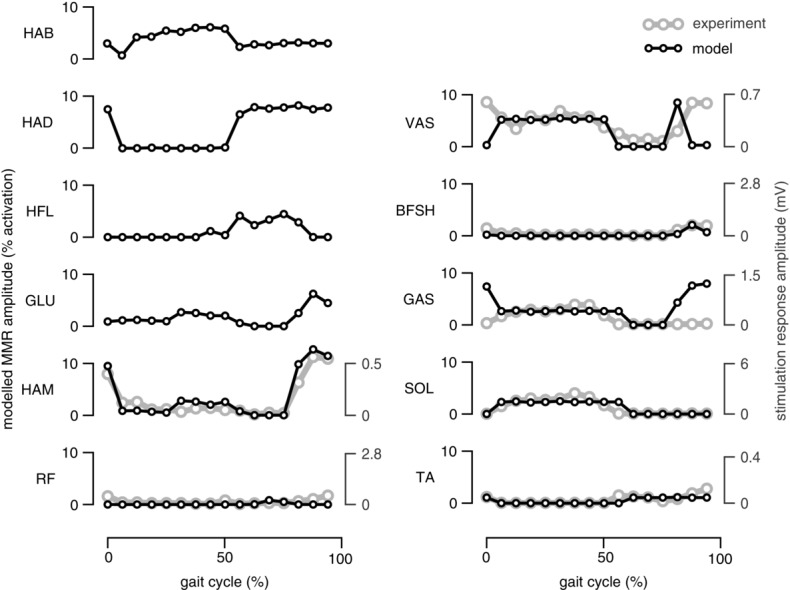
Model-predicted responses to epidural stimulation (black traces) are compared to human experimental data (grey traces) adapted from Courtine et al. (2007). In humans, changes in muscle EMG are observed for several leg muscles when electrical stimulation is applied transcutaneously to the lumbar spine. The peak-to-peak amplitude of these changes varies with the phase of the gait cycle in which the epidural stimulation is applied (divided into 16 phases, marked in open circles, no responses reported for the hip muscles). In the simulation, epidural stimulation is mimicked as 20 ms square-wave impulses simultaneously applied to all afferent pathways at the beginning of each phase of the gait cycle. The resulting peak-to-peak amplitude change in the muscle activations is shown.
Most of the alternative control models of human locomotion emphasize CPGs at the core of the spinal control circuitry (Taga et al. 1991; Taga, 1998; Ogihara & Yamazaki, 2001; Hase et al. 2003; Paul et al. 2005; Kim et al. 2011). From a theoretical standpoint, CPGs provide the advantage of a feedforward drive at the cost of being sensitive to external disturbances when compared to feedback control (Kuo, 2002). The sensory feedback network, on the other hand, shows large robustness to external disturbances (Table 1 and Figs1 and 6) but depends on the interaction with the mechanical environment to drive forward. One way to combine the advantages of both approaches is to understand CPGs as observers of feedback control rather than sole generators of limb motion. Kuo (2002) has shown that such an interpretation can improve the performance for systems subject to unexpected disturbances and sensory noise. Motivated by this idea, Dzeladini et al. (2014) combined the previously developed reflex model for planar locomotion (Geyer & Herr, 2010) with morphing central pattern generators that can learn to predict the sensory output generated by the reflex model. They found that the combined model can regulate walking speed by changing only a few CPG parameters, indicating how CPGs could function as an internal drive and speed control mechanism in a primarily reflex-based control network.
Glossary
- BFSH
short head of biceps femoris
- CE
contractile element
- COM
centre of mass
- CPG
central pattern generator
- DOF
degree of freedom
- EMG
electromyogram
- GAS
gastrocnemius
- GLU
glutei
- GRF
ground reaction force
- HAB
hip abductor
- HAD
hip adductor
- HAM
hamstring
- HFL
hip flexor
- MTU
muscle tendon unit
- PE
parallel elasticity
- RF
rectus femoris
- SE
series elasticity
- SOL
soleus
- TA
tibialis anterior
- VAS
vastii
Appendix A
Musculoskeletal parameters
The properties of the segments, muscles and musculoskeletal attachments are defined based on physiological data (Chandler et al. 1975; Yamaguchi et al. 1990; Visser et al. 1990; Günther & Ruder, 2003; Arnold et al. 2010; Geyer & Herr, 2010; McCullough et al. 2011) and shown in Tables 2, 3 and 4, respectively. The segment parameters include the dimension of the segment dS, the distance of the joints dJ the segment is connected to, the position of the centre of mass dG, the mass mS, and the inertia around the principal axes  ,
,  and
and  . The values dS, dJ and dG are defined either as height (h), length (l) or width (w) as measured from the distal part of the segment for the human model standing straight up. The individual muscle parameters reported in Table 3 are the maximum isometric force Fmax, the maximum contraction velocity vmax, the optimum fibre length lopt, and the tendon slack length lslack. The remaining muscle parameters common to all muscles are the same as in Geyer & Herr (2010). The moment arms of HAB, HAD, HFL, GLU, HAMhip, HAMknee, RFhip and BFSH are assumed to be constant,
  leading to muscle length changes
 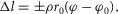 where ρ accounts for the pennation angle of the MTU and φ0 is the reference joint angle when the MTU is at its rest length
  For RFknee, VAS, GASknee, GASankle, SOL and TA variable moment arms
  are assumed with corresponding muscle length changes
  where
where  is a scaling factor defined by the maximum and minimum moment arms, rmax and rmin, at corresponding angles, φmax and φmin. The joint angles are defined so that positive angles indicate extension of the pitch joints and abduction of the roll joints. The zero angle configuration corresponds to a pose of the human model where all the foot contact points lie on the ground plane, the shank, thigh and trunk segments are parallel to the ground plane, and the ankle and hip point backwards while the knee and head point forward. For example, when standing upright, the ankle joints are at 90 deg, the knee and hip pitch joints are at 180 deg, and the hip roll joints are at 0 deg.
Table 2.
Segment parameters
| Trunk | Thigh | Shank | Foot | |
|---|---|---|---|---|
| dS (cm) | 80 (h) | 46 (h) | 46 (h) | 20 (l) 8 (h) |
| dJ (cm) | 20 (w) | 46 (h) | 46 (h) | 16 (l) 8 (h) |
| dG (cm) | 35 (h) | 28 (h) | 28 (h) | 14 (l) 7 (h) |
| mS (kg) | 53.5 | 8.5 | 3.5 | 1.25 |
| Θx (kg m2) | 4.0 | 0.15 | 0.05 | 0.0007 |
| Θy (kg m2) | 2.5 | 0.15 | 0.05 | 0.005 |
| Θz (kg m2) | 1.0 | 0.03 | 0.003 | 0.005 |
dS, the dimension of the segment; dJ, the distance of the joints the segment is connected to; dG, the position of the centre of mass; mS, the mass;  ,
,  and
and  , the inertia around the principal axes. h, height; l, length; w, width.
Table 3.
Muscle parameters
| HAB | HAD | HFL | GLU | HAM | RF | VAS | BFSH | GAS | SOL | TA | |
|---|---|---|---|---|---|---|---|---|---|---|---|
| Fmax (kN) | 3 | 4.5 | 2 | 1.5 | 3 | 1.2 | 6 | 0.35 | 1.5 | 4 | 0.8 |
| vmax (lopt s−1) | 12 | 12 | 12 | 12 | 12 | 12 | 12 | 12 | 12 | 6 | 12 |
| lopt (cm) | 9 | 10 | 11 | 11 | 10 | 8 | 8 | 12 | 5 | 4 | 6 |
| lslack (cm) | 7 | 18 | 10 | 13 | 31 | 35 | 23 | 10 | 40 | 26 | 24 |
Fmax, maximum isometric force; vmax, the maximum contraction velocity of the CE; lopt, the optimal CE length; lslack, the SE slack length.
Table 4.
Musculoskeletal attachment parameters
| Hip |
Knee |
Ankle |
||||||||||||
|---|---|---|---|---|---|---|---|---|---|---|---|---|---|---|
| HAB | HAD | HFL | GLU | HAM | RF | HAM | RF | VAS | BFSH | GAS | GAS | SOL | TA | |
| r0 (cm) | 6 | 3 | 8 | 8 | 8 | 8 | 5 | — | — | 4 | — | — | — | — |
| rmax (cm) | — | — | — | — | — | — | — | 6 | 6 | — | 5 | 6 | 6 | 4 |
| rmin (cm) | — | — | — | — | — | — | — | 4 | 4 | — | 2 | 2 | 2 | 1 |
| φmax (deg) | — | — | — | — | — | — | — | 165 | 165 | — | 140 | 100 | 100 | 80 |
| φmin (deg) | — | — | — | — | — | — | — | 45 | 45 | — | 45 | 180 | 180 | 180 |
| φ0 (deg) | 10 | 15 | 160 | 120 | 150 | 170 | 180 | 125 | 120 | 160 | 165 | 80 | 90 | 110 |
| ρ | 0.7 | 1 | 0.5 | 0.5 | 0.5 | 0.3 | 0.5 | 0.5 | 0.6 | 0.7 | 0.7 | 0.7 | 0.5 | 0.7 |
r0, constant moment arm; rmax and rmin, the maximum and minimum moment arms, with corresponding angles, ϕmax and  ϕ0, the reference joint angle when the MTU is at its rest length
  rho, the pennation angle of the MTU.
Appendix B
Reflex control equations
Reflex pathways that are frequently used in the control network include force feedback ( length feedback (
 velocity feedback (
 proportional-derivative feedback (
 and co-stimulation (
 The general structure of these pathways is shown in eqn (A1),
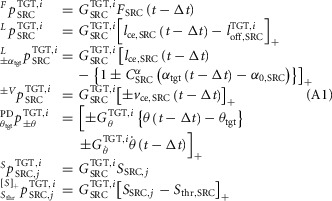 |
where the left superscript indicates the type of the pathway, the right superscript specifies the target muscle (TGT) stimulated by the pathway and the control module (i) the pathway belongs to. The right subscript shows the signal origin as either the source muscle (SRC) or the trunk lean θ. In addition, for the length and co-stimulation pathways a left subscript indicates feedback modulation by either the swing-leg target angle ( or the co-stimulation threshold (
 The symbol [...]+ indicates that only the positive values of the term in the bracket are used. With this notation system, the reflex pathways that generate the muscle stimulations are given below for each muscle individually:
HAB
HAD
HFL
GLU
where 
HAM
RF
VAS
BFSH
where 
 and
and 
GAS
SOL
TA
where STA, 5, st is only active during stance (st).
The swing leg control trigger events (Sw1–Sw4, in Fig.3) are modelled as:
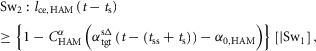 |
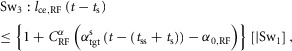 |
where [|Sw1] in Sw2, for example, indicates that Sw2 gets triggered only if Sw1 is already triggered in the swing phase.
Additional information
Competing interests
None declared.
Author contributions
Both authors designed the research, drafted the article, and approved the final version of the manuscript. S.S. implemented the computational model and conducted the simulation studies.
Funding
This work was supported in part by the National Science Foundation (NSF) through the NSF Engineering Research Center (ERC) for Quality of Life Technology (EEC 0540865) and by the NIH through the NICHD National Center for Medical Rehabilitation Research (1R01HD075492).
Supporting information
The following supporting information is available in the online version of this article.
Supplementary Material
Video S1. Neuromuscular model of human locomotion behaviors.
References
- Ackermann M, van den Bogert AJ. Optimality principles for model-based prediction of human gait. J Biomech. 2010;43:1055–1060. doi: 10.1016/j.jbiomech.2009.12.012. [DOI] [PMC free article] [PubMed] [Google Scholar]
- Angeli CA, Edgerton VR, Gerasimenko YP, Harkema SJ. Altering spinal cord excitability enables voluntary movements after chronic complete paralysis in humans. Brain. 2014;137:1394–1409. doi: 10.1093/brain/awu038. [DOI] [PMC free article] [PubMed] [Google Scholar]
- Arnold EM, Ward SR, Lieber RL, Delp SL. A model of the lower limb for analysis of human movement. Ann Biomed Eng. 2010;38:269–279. doi: 10.1007/s10439-009-9852-5. [DOI] [PMC free article] [PubMed] [Google Scholar]
- Bizzi E, Cheung V, d'Avella A, Saltiel P, Tresch M. Combining modules for movement. Brain Res Rev. 2008;57:125–133. doi: 10.1016/j.brainresrev.2007.08.004. [DOI] [PMC free article] [PubMed] [Google Scholar]
- Bizzi E, Cheung VC. The neural origin of muscle synergies. Front Comput Neurosci. 2013;7:51. doi: 10.3389/fncom.2013.00051. [DOI] [PMC free article] [PubMed] [Google Scholar]
- Brown TG. The intrinsic factors in the act of progression in the mammal. Proc R Soc Lond B Biol Sci. 1911;84:308–319. [Google Scholar]
- Capogrosso M, Wenger N, Raspopovic S, Musienko P, Beauparlant J, Luciani LB, Courtine G, Micera S. A computational model for epidural electrical stimulation of spinal sensorimotor circuits. J Neurosci. 2013;33:19326–19340. doi: 10.1523/JNEUROSCI.1688-13.2013. [DOI] [PMC free article] [PubMed] [Google Scholar]
- Chandler RF, Clauser CE, McConville JT, Reynolds HM, Young JW. Investigation of Inertial Properties of the Human Body. Springfield, VA, USA: National Technical Information Service; 1975. Technical report, DTIC document, AD-A016 485. [Google Scholar]
- Cheung VC, d'Avella A, Tresch MC, Bizzi E. Central and sensory contributions to the activation and organization of muscle synergies during natural motor behaviors. J Neurosci. 2005;25:6419–6434. doi: 10.1523/JNEUROSCI.4904-04.2005. [DOI] [PMC free article] [PubMed] [Google Scholar]
- Courtine G, Harkema SJ, Dy CJ, Gerasimenko YP, Dyhre-Poulsen P. Modulation of multisegmental monosynaptic responses in a variety of leg muscles during walking and running in humans. J Physiol. 2007;582:1125–1139. doi: 10.1113/jphysiol.2007.128447. [DOI] [PMC free article] [PubMed] [Google Scholar]
- Cronin NJ, Ishikawa M, Grey MJ, Af Klint R, Komi PV, Avela J, Sinkjaer T, Voigt M. Mechanical and neural stretch responses of the human soleus muscle at different walking speeds. J Physiol. 2009;587:3375–3382. doi: 10.1113/jphysiol.2008.162610. [DOI] [PMC free article] [PubMed] [Google Scholar]
- Damavandi M, Dixon PC, Pearsall DJ. Ground reaction force adaptations during cross-slope walking and running. Hum Movement Sci. 2012;31:182–189. doi: 10.1016/j.humov.2011.06.004. [DOI] [PubMed] [Google Scholar]
- Desai R, Geyer H. Robotics and Biomimetics (ROBIO), 2012 IEEE International Conference on 11–14 Dec. 2012 in Guangzhou. IEEE; 2012. Robust swing leg placement under large disturbances; pp. 265–270. [Google Scholar]
- Desai R, Geyer H. Robotics and Automation (ICRA), 2013 IEEE International Conference on 6–10 May 2013 in Karlsruhe. IEEE; 2013. Muscle-reflex control of robust swing leg placement; pp. 2169–2174. [Google Scholar]
- Dietz V. Proprioception and locomotor disorders. Nat Rev Neurosci. 2002;3:781–790. doi: 10.1038/nrn939. [DOI] [PubMed] [Google Scholar]
- Dominici N, Ivanenko YP, Cappellini G, d'Avella A, Mondì V, Cicchese M, Fabiano A, Silei T, Di Paolo A, Giannini C, Poppele RE, Lacquaniti F. Locomotor primitives in newborn babies and their development. Science. 2011;334:997–999. doi: 10.1126/science.1210617. [DOI] [PubMed] [Google Scholar]
- Dzeladini F, van den Kieboom J, Ijspeert A. The contribution of a central pattern generator in a reflex-based neuromuscular model. Front Hum Neurosci. 2014;8:371. doi: 10.3389/fnhum.2014.00371. [DOI] [PMC free article] [PubMed] [Google Scholar]
- Eng JJ, Winter DA. Kinetic analysis of the lower limbs during walking: what information can be gained from a three-dimensional model? J Biomech. 1995;28:753–758. doi: 10.1016/0021-9290(94)00124-m. [DOI] [PubMed] [Google Scholar]
- Ferris DP, Louie M, Farley CT. Running in the real world: adjusting leg stiffness for different surfaces. Proc R Soc Lond B Biol Sci. 1998;265:989–994. doi: 10.1098/rspb.1998.0388. [DOI] [PMC free article] [PubMed] [Google Scholar]
- Gerasimenko Y, Roy RR, Edgerton VR. Epidural stimulation: comparison of the spinal circuits that generate and control locomotion in rats, cats and humans. Exp Neurol. 2008;209:417–425. doi: 10.1016/j.expneurol.2007.07.015. [DOI] [PMC free article] [PubMed] [Google Scholar]
- Geyer H, Herr H. A muscle-reflex model that encodes principles of legged mechanics produces human walking dynamics and muscle activities. IEEE Trans Neural Syst Rehabil Eng. 2010;18:263–273. doi: 10.1109/TNSRE.2010.2047592. [DOI] [PubMed] [Google Scholar]
- Grey MJ, Ladouceur M, Andersen JB, Nielsen JB, Sinkjær T. Group II muscle afferents probably contribute to the medium latency soleus stretch reflex during walking in humans. J Physiol. 2001;534:925–933. doi: 10.1111/j.1469-7793.2001.00925.x. [DOI] [PMC free article] [PubMed] [Google Scholar]
- Grillner S. Biological pattern generation: the cellular and computational logic of networks in motion. Neuron. 2006;52:751–766. doi: 10.1016/j.neuron.2006.11.008. [DOI] [PubMed] [Google Scholar]
- Grillner S, Zangger P. On the central generation of locomotion in the low spinal cat. Exp Brain Res. 1979;34:241–261. doi: 10.1007/BF00235671. [DOI] [PubMed] [Google Scholar]
- Guertin PA. The mammalian central pattern generator for locomotion. Brain Res Rev. 2009;62:45–56. doi: 10.1016/j.brainresrev.2009.08.002. [DOI] [PubMed] [Google Scholar]
- Günther M, Ruder H. Synthesis of two-dimensional human walking: a test of the λ-model. Biol Cybern. 2003;89:89–106. doi: 10.1007/s00422-003-0414-x. [DOI] [PubMed] [Google Scholar]
- Hansen N. Towards a New Evolutionary Computation. Springer; 2006. The CMA evolution strategy: A comparing review; pp. 75–102. [Google Scholar]
- Harkema S, Gerasimenko Y, Hodes J, Burdick J, Angeli C, Chen Y, Ferreira C, Willhite A, Rejc E, Grossman RG, Edgerton VR. Effect of epidural stimulation of the lumbosacral spinal cord on voluntary movement, standing, and assisted stepping after motor complete paraplegia: a case study. Lancet. 2011;377:1938–1947. doi: 10.1016/S0140-6736(11)60547-3. [DOI] [PMC free article] [PubMed] [Google Scholar]
- Harkema SJ. Plasticity of interneuronal networks of the functionally isolated human spinal cord. Brain Res Rev. 2008;57:255–264. doi: 10.1016/j.brainresrev.2007.07.012. [DOI] [PMC free article] [PubMed] [Google Scholar]
- Hase K, Miyashita K, Ok S, Arakawa Y. Human gait simulation with a neuromusculoskeletal model and evolutionary computation. J Visual Comp Animat. 2003;14:73–92. [Google Scholar]
- Hof A, Duysens J. Responses of human hip abductor muscles to lateral balance perturbations during walking. Exp Brain Res. 2013;230:301–310. doi: 10.1007/s00221-013-3655-5. [DOI] [PubMed] [Google Scholar]
- Holsheimer J. Which neuronal elements are activated directly by spinal cord stimulation. Neuromodulation. 2002;5:25–31. doi: 10.1046/j.1525-1403.2002._2005.x. [DOI] [PubMed] [Google Scholar]
- Ijspeert AJ. Central pattern generators for locomotion control in animals and robots: a review. Neural Netw. 2008;21:642–653. doi: 10.1016/j.neunet.2008.03.014. [DOI] [PubMed] [Google Scholar]
- Ivanenko YP, Poppele RE, Lacquaniti F. Five basic muscle activation patterns account for muscle activity during human locomotion. J Physiol. 2004;556:267–282. doi: 10.1113/jphysiol.2003.057174. [DOI] [PMC free article] [PubMed] [Google Scholar]
- Kajita S, Kanehiro F, Kaneko K, Yokoi K, Hirukawa H. Intelligent Robots and Systems, 2001. Proceedings. 2001 IEEE/RSJ International Conference on 29 Oct–3 Nov 2001 in Maui, HI. Vol. 1. IEEE; 2001. The 3D linear inverted pendulum mode: A simple modeling for a biped walking pattern generation; pp. 239–246. [Google Scholar]
- Kim Y, Tagawa Y, Obinata G, Hase K. Robust control of CPG-based 3D neuromusculoskeletal walking model. Biol Cybern. 2011;105:269–282. doi: 10.1007/s00422-011-0464-4. [DOI] [PubMed] [Google Scholar]
- Knikou M, Rymer WZ. Effects of changes in hip joint angle on H-reflex excitability in humans. Exp Brain Res. 2002;143:149–159. doi: 10.1007/s00221-001-0978-4. [DOI] [PubMed] [Google Scholar]
- Kuo AD. The relative roles of feedforward and feedback in the control of rhythmic movements. Motor Control. 2002;6:129–145. doi: 10.1123/mcj.6.2.129. [DOI] [PubMed] [Google Scholar]
- Kutch JJ, Valero-Cuevas FJ. Challenges and new approaches to proving the existence of muscle synergies of neural origin. PLoS Comput Biol. 2012;8:e1002434. doi: 10.1371/journal.pcbi.1002434. [DOI] [PMC free article] [PubMed] [Google Scholar]
- Lipfert SW, Günther M, Renjewski D, Grimmer S, Seyfarth A. A model-experiment comparison of system dynamics for human walking and running. J Theor Biol. 2012;292:11–17. doi: 10.1016/j.jtbi.2011.09.021. [DOI] [PubMed] [Google Scholar]
- McCullough MB, Ringleb SI, Arai K, Kitaoka HB, Kaufman KR. Moment arms of the ankle throughout the range of motion in three planes. Foot Ankle Int. 2011;32:300–306. doi: 10.3113/FAI.2011.0300. [DOI] [PubMed] [Google Scholar]
- Matsuoka K. Sustained oscillations generated by mutually inhibiting neurons with adaptation. Biol Cybern. 1985;52:367–376. doi: 10.1007/BF00449593. [DOI] [PubMed] [Google Scholar]
- Meunier S, Penicaud A, Pierrot-Deseilligny E, Rossi A. Monosynaptic Ia excitation and recurrent inhibition from quadriceps to ankle flexors and extensors in man. J Physiol. 1990;423:661–675. doi: 10.1113/jphysiol.1990.sp018046. [DOI] [PMC free article] [PubMed] [Google Scholar]
- Minassian K, Persy I, Rattay F, Pinter MM, Kern H, Dimitrijevic MR. Human lumbar cord circuitries can be activated by extrinsic tonic input to generate locomotor-like activity. Hum Movement Sci. 2007;26:275–295. doi: 10.1016/j.humov.2007.01.005. [DOI] [PubMed] [Google Scholar]
- Mochon S, McMahon TA. Ballistic walking. J Biomech. 1980;13:49–57. doi: 10.1016/0021-9290(80)90007-x. [DOI] [PubMed] [Google Scholar]
- Murray M, Mollinger L, Gardner G, Sepic S. Kinematic and EMG patterns during slow, free, and fast walking. J Orthop Res. 1984;2:272–280. doi: 10.1002/jor.1100020309. [DOI] [PubMed] [Google Scholar]
- Ogihara N, Yamazaki N. Generation of human bipedal locomotion by a bio-mimetic neuro-musculo-skeletal model. Biol Cybern. 2001;84:1–11. doi: 10.1007/PL00007977. [DOI] [PubMed] [Google Scholar]
- Orlovsky GN, Deliagina T, Grillner S, Orlovskii G, Grillner S. Neuronal Control of Locomotion: From Mollusc to Man. Oxford University Press; 1999. [Google Scholar]
- Paul C, Bellotti M, Jezernik S, Curt A. Development of a human neuro-musculo-skeletal model for investigation of spinal cord injury. Biol Cybern. 2005;93:153–170. doi: 10.1007/s00422-005-0559-x. [DOI] [PubMed] [Google Scholar]
- Perry J, Burnfield JM. Gait Analysis: Normal and Pathological Function. 2nd edn. SLACK, Inc; 2010. [Google Scholar]
- Raibert M. Legged Robots that Balance. Cambridge, Massachusetts: MIT Press; 1986. [Google Scholar]
- Rose J, Gamble JG, Adams JM. Human Walking. Philadelphia: Lippincott Williams & Wilkins; 2006. [Google Scholar]
- Rossignol S, Barrière G, Frigon A, Barthélemy D, Bouyer L, Provencher J, Leblond H, Bernard G. Plasticity of locomotor sensorimotor interactions after peripheral and/or spinal lesions. Brain Res Rev. 2008;57:228–240. doi: 10.1016/j.brainresrev.2007.06.019. [DOI] [PubMed] [Google Scholar]
- Seyfarth A, Günther M, Blickhan R. Stable operation of an elastic three-segment leg. Biol Cybern. 2001;84:365–382. doi: 10.1007/PL00007982. [DOI] [PubMed] [Google Scholar]
- Sinkjær T, Andersen JB, Ladouceur M, Christensen LO, Nielsen JB. Major role for sensory feedback in soleus EMG activity in the stance phase of walking in man. J Physiol. 2000;523:817–827. doi: 10.1111/j.1469-7793.2000.00817.x. [DOI] [PMC free article] [PubMed] [Google Scholar]
- Song S, Desai R, Geyer H. Engineering in Medicine and Biology Society (EMBC), 2013 35th Annual International Conference of the IEEE on 3–7 July 2013 in Osaka. IEEE; 2013. Integration of an adaptive swing control into a neuromuscular human walking model; pp. 4915–4918. [DOI] [PubMed] [Google Scholar]
- Song S, Geyer H. Robotics and Automation (ICRA), 2012 IEEE International Conference on 14–18 May 2012 at Saint Paul, Minnesota. IEEE; 2012. Regulating speed and generating large speed transitions in a neuromuscular human walking model; pp. 511–516. [Google Scholar]
- Song S, Geyer H. Engineering in Medicine and Biology Society (EMBC), 2013 35th Annual International Conference of the IEEE on 3–7 July 2013 in Osaka. IEEE; 2013. Generalization of a muscle-reflex control model to 3D walking; pp. 7463–7466. [DOI] [PubMed] [Google Scholar]
- Stokes V, Andersson C, Forssberg H. Rotational and translational movement features of the pelvis and thorax during adult human locomotion. J Biomech. 1989;22:43–50. doi: 10.1016/0021-9290(89)90183-8. [DOI] [PubMed] [Google Scholar]
- Taga G. A model of the neuro-musculo-skeletal system for anticipatory adjustment of human locomotion during obstacle avoidance. Biol Cybern. 1998;78:9–17. doi: 10.1007/s004220050408. [DOI] [PubMed] [Google Scholar]
- Taga G, Yamaguchi Y, Shimizu H. Self-organized control of bipedal locomotion by neural oscillators in unpredictable environment. Biol Cybern. 1991;65:147–159. doi: 10.1007/BF00198086. [DOI] [PubMed] [Google Scholar]
- Torres-Oviedo G, Ting LH. Muscle synergies characterizing human postural responses. J Neurophysiol. 2007;98:2144–2156. doi: 10.1152/jn.01360.2006. [DOI] [PubMed] [Google Scholar]
- Tresch MC, Jarc A. The case for and against muscle synergies. Curr Opin Neurobiol. 2009;19:601–607. doi: 10.1016/j.conb.2009.09.002. [DOI] [PMC free article] [PubMed] [Google Scholar]
- Tresch MC, Saltiel P, Bizzi E. The construction of movement by the spinal cord. Nat Neurosci. 1999;2:162–167. doi: 10.1038/5721. [DOI] [PubMed] [Google Scholar]
- Umberger BR. Stance and swing phase costs in human walking. J R Soc Interface. 2010;7:1329–1340. doi: 10.1098/rsif.2010.0084. [DOI] [PMC free article] [PubMed] [Google Scholar]
- Umberger BR, Gerritsen KG, Martin PE. A model of human muscle energy expenditure. Comput Methods Biomech Biomed Engin. 2003;6:99–111. doi: 10.1080/1025584031000091678. [DOI] [PubMed] [Google Scholar]
- Visser J, Hoogkamer J, Bobbert M, Huijing P. Length and moment arm of human leg muscles as a function of knee and hip-joint angles. Eur J Appl Physiol Occup Physiol. 1990;61:453–460. doi: 10.1007/BF00236067. [DOI] [PubMed] [Google Scholar]
- Wren TA, Patrick Do K, Rethlefsen SA, Healy B. Cross-correlation as a method for comparing dynamic electromyography signals during gait. J Biomech. 2006;39:2714–2718. doi: 10.1016/j.jbiomech.2005.09.006. [DOI] [PubMed] [Google Scholar]
- Wu A, Geyer H. The 3-D spring–mass model reveals a time-based deadbeat control for highly robust running and steering in uncertain environments. IEEE Trans Robot. 2013;29:1114–1124. [Google Scholar]
- Yamaguchi G, Sawa A, Moran D, Fessler M, Winters J. A Survey of Human Musculotendon Actuator Parameters. Multiple Muscle Systems. Springer-Verlag; 1990. pp. 717–773. [Google Scholar]
- Yin K, Loken K, van de Panne M. Simbicon: Simple biped locomotion control. ACM Trans Graph. 2007;26:105-1–105-10. [Google Scholar]
Associated Data
This section collects any data citations, data availability statements, or supplementary materials included in this article.
Supplementary Materials
Supplementary Material
Video S1. Neuromuscular model of human locomotion behaviors.