Abstract
In this paper, we present a tendon-driven continuum robot for endoscopic surgery. The robot has two sections for articulation actuated by tendon wires. By actuating the two sections independently, the robot can generate a variety of tip positions while maintaining the tip direction. This feature offers more flexibility in positioning the tip for large viewing angles of up to 180 degrees than does a conventional endoscope. To accurately estimate the tip position at large viewing angles, we employed kinematic mapping with a tension propagation model including friction between the tendon wires and the robot body. In a simulation study using this kinematic-mapping, the two-section robot at a target scale (outer diameter 1.7 mm and length 60 mm) produced a variety of tip positions within 50-mm ranges at the 180°-angle view. In the experimental validation, a 10:1 scale prototype performed three salient postures with different tip positions at the 180°-angle view. The proposed forward kinematic mapping (FKM) predicted the tip position within a tip-to-tip error of 6 mm over the 208-mm articulating length. The tip-to-tip error by FKM was significantly less than the one by conventional piecewise-constant-curvature approximation (PCCA) (FKM: 5.9 ± 2.9 mm vs. PCCA: 23.7 ± 3.6 mm, n=15, P < 0.01).
Keywords: Medical robotics, Dexterous manipulators, Robot kinematics, Surgery
I. INTRODUCTION
INTRACRANIAL aneurysms occur at the branching point of major arteries in the anterior circulation near the base of the brain [1]. Surgical treatment for intracranial aneurysms aims to isolate the aneurysmal sac from circulation and to prevent the thin wall of the blood vessel from rupturing. In the surgical approach, a clip is placed at the neck of the aneurysmal sac under rigid endoscopic guidance. Endoscopy is used to inspect the lesion before clipping, to perform clipping itself, and to assess proper placement of the clip around the neck of the sac to be isolated. However, rigid endoscopy has inherent limitations and may not provide the most comprehensive approach to aneurysm clipping. The endoscope provides the topographic relationship of the aneurysm to the parent, branching, and perforating vessels and to adjacent structures before clipping. For post-clipping evaluation, the endoscope is used to assess clip position, to confirm the completeness of aneurysm obliteration, and to preclude the occlusion or constriction of parent, branching, or perforating vessels. As Fischer et al. indicated [2], the visual inspection of the surrounding critical structure is vitally important to ensure the safety of the procedure as well as to minimize the risk of future rupturing. The rigid endoscope does not enable inspection around or behind aneurysms without displacing neurovascular structures. Some aneurysms are not amenable to clipping because of their location and the lack of a method for complete inspection [3]. Therefore, there exists a need to provide physicians with endoscopes that not only offer a wider view angle and viewing direction but also hold their rigidity during clipping operations.
A potential solution to increasing the viewing capacities of the endoscope is to house a flexible endoscope in a multi-section robot, in particular a tendon-driven continuum robot. We chose a tendon-driven robot because we believe it is safe for intracranial use. A tendon-driven robot has passive compliance to external collision when tendons are held by appropriate tensions. This feature ensures increased safety for patients in the case of high risk of contact with anatomies. A similar position is proposed by Camarillo et al. [4], [5], who described a tendon-driven steerable catheter using a multi-section robot. For independent control of multi-sections, they proposed a linear beam configuration model that transforms beam configuration to tendon displacement including both mechanical and geometrical coupling among multi-sections in intra-cardiac catheter operations.
The tendon-driven continuum robot, however, needs to be further refined for applicability to endoscopic support. The current state of the art in control and trajectory planning of the tendon-driven robot assumes that the one bending unit, or section, has constant curvature throughout the multiple sections as the pulling force propagates constantly through sections [6], [7]. In reality, a friction force between tendons and their guide structures within a section reduces the propagating pulling force, thus lessening the curvature from the proximal to the distal end of the robot. Limitations in size and material selection prohibit the reduction of this friction force, making it unrealistic to ignore the friction force in control and trajectory planning.
This issue motivated us to incorporate friction in kinematic mapping and to extend control and trajectory planning to develop a flexible neuro-endoscope primarily for surgical clipping of intracranial aneurysms, but also applicable for other endoscopic procedures. Specifically, in this paper, we propose the development and assessment of a novel, multi-section continuum robot using tendon wires. The proposed robot consists of multiple continuum-bending elements within one section by using a backbone machined monolithically. The kinematic mapping that we developed takes into account the salient features of friction in a tendon wire when we control the curvature of the robot using tension as an input. In a simulation study using this kinematic-mapping, the two-section robot at a target scale (outer diameter 1.7 mm and length 60 mm) was tested for producing a variety of tip positions within 50-mm ranges at the 180°-angle view. In the experimental validation, a 10:1 scale prototype was fabricated to assess the feasibility of neuro-endoscopic examination. To the best of our knowledge, this approach, which considers the salient features of tendon friction in kinematic mapping by a continuum robot, is original and has not previously been reported in the literature.
II. LITERATURE REVIEW
Improved instrumentation (e.g., endoscopes and catheters) using a continuum robot with multi-section articulation has been an area of active interest in clinical and engineering research groups. The first set of prior art in a continuum robot uses a concentric-tube [8], [9]. The concentric-tube robot comprises precurved elastic tubes arranged in a concentric fashion. To control this robot with multi-sections, these tubes are rotated and translated with respect to one another. Bending moments are built-in as precurved tubes and are transmitted by rotational and translational motion of tubes. The second approach uses a multi-backbone robot in push-pull actuation [10], [11]. Among the multiple backbones, one primary back-bone is centrally located and is attached to a base disk and an end disk. The secondary backbones are attached to the end disk and are equidistant from each other. To generate bending moments, the secondary backbones are pushed and pulled against the base disk. These multi-section robots have been proposed for application to skull-based surgeries [12], neuro-endoscopes for endoscopic third ventriculostomy and choroid plexus cauterization [13], single-port surgery [14], and transurethral surveillance and interventions [15].
An approach using a backbone with flexible and rigid portions in one tube material has been proposed [16] [17]. Mapping from the tension in the tendons to the posture has been investigated experimentally in the absence of a tension propagation model in these studies. Here, we propose forward kinematic mapping (FKM) with a tension propagation model to characterize the friction in the tendon-driven robot. We also use the novel approach of separating the wire guides from the backbone to avoid transmitting the axial force to the backbone. These separated wire guides align to the rigid portions in the backbone, and form tandem linear springs that we modeled as pure rotational springs in the tension propagation model.
The tendon-driven robot is also used in combination with a locking mechanism. Zuo et al. proposed a pneumatic locking mechanism with a bellows backbone [18]. The bellows back-bone is locked by flexible toothed links located on the outside of the backbone. The robot can actuate the toothed links by pneumatic actuator without magnetic materials. Similarly, Sturges et al. proposed another locking mechanism [19]. Chained beads with a single tendon at the centroid of the robot are utilized to lock the shape of the robot. In this design, the tendon is used to transmit the axial force to the beads and presses the beads to enhance the friction between the beads. We expect that the FKM we propose can also analyze the articulation shape and the locking stability of these types of robots: the FKM can directly map the tension in the tendon at the proximal end to both the posture and the tension distribution in the robot.
Zhang et al. proposed elastic modeling with tension in the tendon for steerable electrode arrays [20]. The tension in the single tendon embedded in the continuum elastic body was modeled with a constant friction force. In considering that study, our tension propagation model determines the friction force as a function of the robot posture to improve model accuracy at a large bending angle. Our FKM can also map tension in multiple tendons to the posture. Therefore, we expect that the FKM is useful to improve analysis of the posture of these robots with a continuum elastic body.
A friction model in tendon-driven systems has been proposed for a cable-conduit system where cables pass through conduits to actuate remote instruments [21] [22]. These papers proposed a tension transmission model in tendons with a fixed-path routing. The variation of tension due to friction effects is modeled as an exponential function that has similar monotonically reducing or increasing effects to equation (10). In considering these papers, our main contribution is to map the tension distribution in tendons to the posture of the tendon-driven continuum robot. To determine the continuum robot posture we defined a series of linear springs in the routing of tendons and combined the mechanics model of the springs. Our approach provides a simple iterative computation for kinematics of the tendon-driven continuum robot even when the robot has multiple tendons and multi-sections. Consequently, we expect that our approach can be integrated to feedback control loops with sensors, and the trajectory can be planned with a simple computational algorithm.
III. MATERIALS AND METHODS
A. Mechanical Design
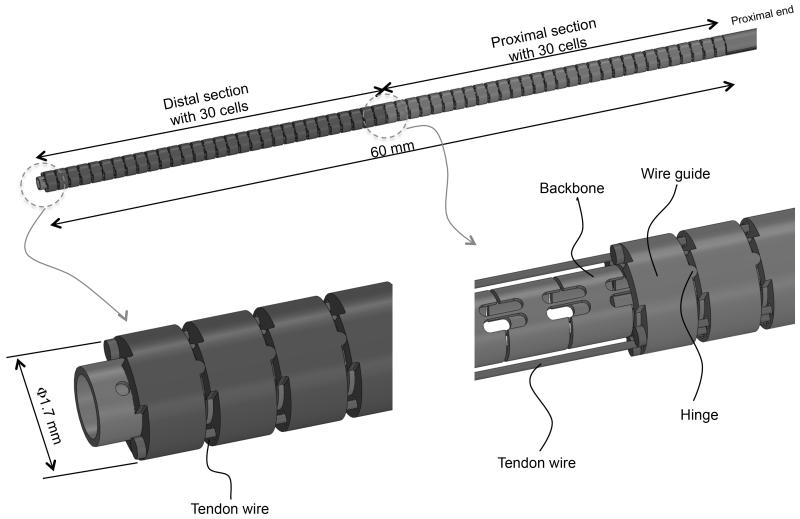
The continuum robot we propose is composed of a back-bone, tendon wires, and wire guides (Fig. 1). The robot has an outer diameter (O.D.) of 1.7 mm and a length of 60 mm and consists of two sections, each with one degree of freedom. The robot has a 0.7-mm-diameter tool channel for imaging fibers. Two groups of three tendon wires run opposite each other through wire guides. The two groups of tendon wires start at the robots proximal extremities and end at the robots midpoint. The other tendon wires start at the robots proximal extremities and end at the distal extremities. The tendon wires are placed 0.65 mm from the centroid of the robot. This length is referred to as the tendons moment arm in Table I. Through differential variation of the tensions in the tendon wires, the tensions are transduced into the bending moment at the wire guides. The bending moment bends the backbone at the distal or proximal section.
Fig. 1.
Two-section continuum robot.
TABLE I.
Mechanical Specifications of the Robot
| Mechanical Parameter | Value |
|---|---|
| Length of cell | 1.0 mm |
| Number of cells | 60* |
| Bending stiffness of cell | 2.0 × 10⁻²Nm/rad† |
| Moment arm of tendons | 0.65 mm |
Total number of two sections. Proximal and distal sections have thirty cells.
The stiffness includes an inserted tool.
The backbone is an elastic tube with flexible and rigid portions periodically spaced along its length. The wire guides align with the rigid portions so that bending moments are applied only at the rigid portions. The length of the rigid portions is larger than the length of the wire guides. This feature makes the amount of bending moment transmitted robustly against misalignment between the guides and the rigid portions. The tendon wires between the wire guides pass through a free space without any contact with the wire guides. Therefore, tensions between the adjoining wire guides are not reduced by the friction effect. The flexible portion between two rigid portions and guides is regarded as a constant curvature element (cell) within one section under bending. Each cell has a length of 1 mm and a bending stiffness of 2.0 × 10⁻² Nm/rad including imaging fiber stiffness for endoscopy. As we discuss below, the cells simplify kinematic modeling of both uneven curvatures and frictions.
The backbone and the tendon wires are made of a super-elastic nickel-titanium (NiTi) alloy. The backbone is cut into flexures of cells from a plain pipe. The outer diameter of the backbone is 1 mm and the wall thickness is 0.15 mm. The wire guides are made of stainless steel. The wire guides have eyelets to hold the tendon wires at 0.2 mm diameter. The tendon wires are 0.16-mm-diameter wire ropes with a tension limitation of 5 N. The limitation was determined by Youngs modulus of NiTi at Austenite phase (50 GPa), the distortion tolerance for linear elastic region (0.5%), and the diameter. The structure was designed in SolidWorks, 3D CAD design software. The bending stiffness of the backbone was calculated by a finite element method using ANSYS simulation software, to ensure linear spring constant of the backbone within maximum tip deflections.
Bending two sections independently allows the robot to generate a variety of posture combinations with curvatures at the distal and the proximal sections while maintaining the tip direction.
B. Forward Kinematic Mapping
We formulated the forward kinematic mapping (FKM) of the robot from the input tension in a tendon wire to the posture of the robot.
The FKM in our study incorporates the piecewise constant-curvature approximation presented in the prior art [6], [7], [23]. Likewise, this approximation has been applied to many multi-section continuum robots in the medical field [4], [5], [8], [10] because the constant curvature can facilitate analytical frame transformations and additional analysis on topics such as differential kinematics and real-time control [23]. In our study, to perform a more realistic estimation of the tip position and the tension in a tendon wire, we introduced the tension propagation model with friction in tendons into the FKM, incorporating the piecewise constant-curvature approximation. Since friction effects are predominant at large tip angles, the FKM is useful for the performance analysis of large angle-view tasks.
For the configuration parameters of the robot in the FKM, we decomposed the robot into multiple cells, which are units of curvature. By concatenating these cell curvatures, the FKM describes the posture of the robot even if the posture has uneven curvature.
1) Assumptions in Modeling
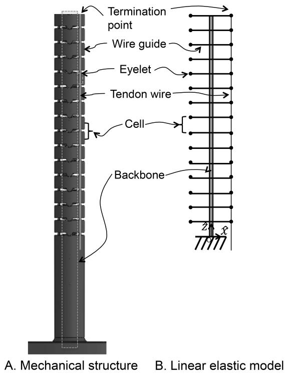
To analyze the mapping from the tension in the tendon wires to the curvatures of the cells, we assume the robot functions as a lumped-parameter model consisting of cells with linear springs, as illustrated in Fig. 2. Each cell has backbone with a linear spring constant for bending, pictured in black in Fig. 2. There is an input of tension in the tendon wire as it is pulled at the proximal end. Bending of the robot follows this tendon actuation because the tendon wire ends at cell n, which is the distal end of the robot, and it applies a bending moment to the cell n.
Fig. 2.
Cell model for the continuum robot. A, Mechanical structure of the robot; B, Corresponding lumped-parameter model for A.
The following assumptions have been made for this lumped-parameter model:
-
A1:
The robot does not extend or contract in the longitudinal direction because the wire guides do not transfer axial forces to the backbone.
-
A2:
Each cell bends in a circular shape. This assumption was verified in [4] for a tendon-driven continuum robot without a longitudinal contraction.
-
A3:
The inclined angle between wires and wire guides is small. This assumption is valid when the robot has enough cells to make the bending angles of cells small enough.
-
A4:
Eyelets in the wire guide are assumed to be points. The wire is subject to friction forces at every eyelet. Friction forces and normal forces acting on the wires are concentrated forces. The direction of normal forces is a tangential direction of a backbone in each cell.
-
A5:
Quasi-static equilibrium is satisfied. Friction forces are equal to maximum static friction forces proportional to the normal force at eyelets.
-
A6:
The gravitational force against bending shape is ignored. For a small continuum robot with millimeter size, this assumption was verified in [24].
-
A7:
The bending stiffness of tendons was not taken into consideration.
2) Coordinate Frames
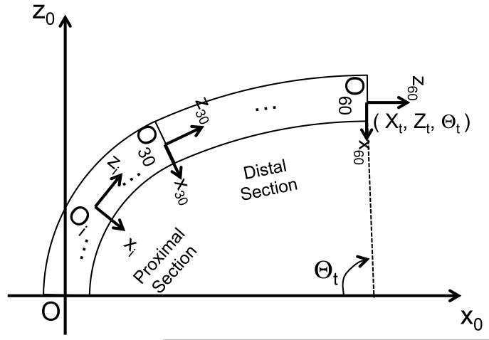
Fig. 3 shows a schematic joint configuration, using a frame convention, of the tendon-driven continuum robot proposed in this paper. We set the frame of each cell in the section of the tendon-driven continuum robot as an individual joint coordinate. These coordinates represent the robot posture. We model a set of cells in the section of the robot as under-actuated joints at each section of the robot.
Fig. 3.
Frame convention of robot. The proximal end of the tendon-driven continuum robot is mechanically grounded on the task space coordinate. The +z-axis is defined to be tangent to the base of the robot. Each of the proximal and distal sections of the robot has thirty joint coordinates.
3) Constitutive Equation
The first step in the analysis is to formalize a constitutive equation between curvatures and tensions in each cell of the lumped-parameter model. Estimating tension for each cell from input tension at the proximal end follows this analysis. Subsequently, we formulate mapping from tension in the tendon wires at the proximal end to curvatures of all cells in the robot.
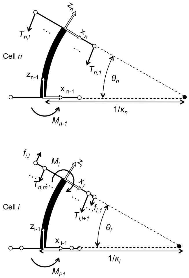
To map tendon wire tensions at each cell to its curvature, we formulate a constitutive equation for cells in the lumped-parameter model. For this constitutive equation, we analyze the cells bending moment equilibrium considering a propagation of bending moment from the termination point of cell n to the other cells, from the distal side to the proximal side. The l tendon wires for the distal section apply actuation forces Tn,1 to Tn,l at the termination point in cell n pictured in Fig. 4. Assuming A2 and A3, the resultant bending moment Mn−1 of all tendons in cell n is described as,
| (1) |
where d denotes the distance between the eyelet and centroid of the robot. Therefore, by using (1), a constitutive equation for cell n is described as,
| (2) |
where kn denotes curvature of cell n and sn denotes its length. Equation (2) is a Hookes law with a rotational spring and bending moment. Kθ is an effective bending stiffness per one cell (in Nm/rad). This is the equivalent rotational-spring constant where the cell is fixed on the one end and subjected to the bending moment on the other end.
Fig. 4.
Bending moment equilibrium for cells
For cell i, which is 1≤i<n and the most distal cell in the proximal section, another tendon wire for the proximal section applies another actuation force Tn,l+1 to Tn,m. Also the bending moment Mi propagates from cell (i + 1), and friction force fi+1,1, fi+1,l from the tendon wires for the distal section acts as another bending moment in the lumped-parameter model, as shown in Fig. 4. Therefore, the bending moment for cell i is described as,
| (3) |
By combining (3) with (1), we formalize a relationship between bending moment and tension in multiple tendon wires at cell i as follows:
| (4) |
Therefore, a constitutive equation for cell i is the same equation as equation (2). Equation (2) allows one to map the tendon wire tension of each cell to its curvature.
4) Tension Propagation Model
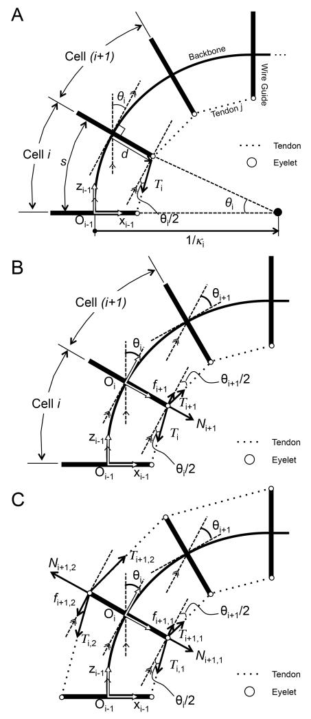
To map tension in the tendon wire at a proximal end to tension in the tendon wire at each cell, we analyze propagation of tension in the tendon wire with friction force between adjoining cells. Fig. 5 shows this relationship combining bending angles for cells i and (i + 1). In Fig. 5 A, a single tendon on a shortening side is subjected to tension Ti. By using (2), we calculate curvature ki and bending angle θi in cell i shown in Fig. 5 B. The bending angle θi at cell i is a bending angle of cell i on the frame Oi−1 in Fig. 5 A. Tension Ti is decreased by friction force fi+1 at the eyelet between cells i and (i + 1).
Fig. 5.
Tensions with static friction force at eyelets between adjoining cells. A, Relationship between bending angle and tension at cell i; B, Tension propagation from cell i to cell i + 1 in a single tendon; C, Tension propagation from cell i to cell i + 1 in an antagonistic pair of tendons.
Under assumption A4, force equilibrium is described as,
| (5) |
| (6) |
Under assumption A5, friction force is proportional to normal force with friction coefficient μ,
| (7) |
Under assumption A3, equation (6) is described by,
| (8) |
Using equations (5), (7), and (8), and assuming, sin(θi/2) ≃ sin(θi+1/2), a ratio of tension Ti+1 and Ti is described explicitly as,
| (9) |
The assumption of sin(θi/2) ≃ sin(θi+1/2) gives an approximation of the variation ratio of the bending angle of adjoining cells in many situations, when there are enough cells in the robot. Equation (9) allows one to calculate tension Ti+1,j by using only the parameters of cell i. By using (2) and (9) alternately, tensions and curvatures for all cells in the robot are calculated.
To extend equation (9) to multiple-tendon situations, we analyze a robot with an antagonistic pair of tendons, 1 and 2. Fig. 5 C shows the relationship between tensions and friction forces for a robot with an antagonistic pair of tendons. Tendon 2 is located on the extending side of the robot. In this case, friction force fi+1,2 increases the tension Ti,2. We represent the direction of the friction force in the antagonistic pair of tendons by using the sign function of tendon position dj and resultant moment for tendon j in cell i. Therefore, the ratio of Ti,j and Ti+1,j is described as,
| (10) |
Equation (10) evolves the tension in the antagonistic pair of tendons at cell i to tension at cell (i + 1) with bending angles of cell i. Specifically, the sign function in (10) manages the direction of the friction force against tension in the tendon correlating the friction force to the position of tendons and the bending direction of cell i. The sign function of the resultant moment denotes the bending direction of cell i, and the sign function of di,j is consistent with the sign of di,j on x-axis in the frame of cell i. When the bending angle increases , tension Ti,1 in Fig. 5 C decreases to Ti+1,1 while tension Ti,2 increases to Ti+1,2. To map the posture of the robot based on the curvatures of all cells, we utilized a homogeneous transformation matrix with the arc parameters in [23] and applied the matrix for the cells. Our approach is completely different from the approach outlined in [23] because the matrix is applied to cells instead of sections. The decomposition into cells allows us to calculate the posture of the robot with uneven curvatures by a simple calculation.
IV. EXPERIMENTAL RESULTS
We conducted series of experiments to assess the ability of the robot to maintain certain visualization angle to assess the cranial aneurysms (hereafter referred to as angle-view task). In all experiments, we set 180 degrees as stringent conditions in angle-view tasks. The 180°-angle view (i.e., backward visualization) is important to observe aneurysms from the blind spot behind the vessels. Moreover, this angle is the most stringent condition to assess performance considering the tension limitation of tendon wire, because the tension in tendon wires for actuation is increased by friction between tendon wires and eyelets at larger bending angles.
First, we collected the friction coefficient between guides and tendon wires, namely constant μ in equation (10), to plug the measurement value into the FKM. All our data in these studies were obtained using this friction coefficient. We prepared eyelets and wires as test pieces for measurement.
The second set of experiments simulated the variability of the tip position at the 180° - angle and 45° -angle view. We calculated possible curvature combinations of the two robot sections and their postures by using an FKM that covers the tension limitation of the robot.
The third set of experiments involves a physical prototype to validate the postures against the simulations. We developed a 10:1 scale prototype of the two-section robot for validation. By pulling the two tendon wires for the two sections of the prototype, we observed postures in the motion range by maintaining the 180°-angle view. We compared the measured positions of every cell with values predicted by the FKM as well as a conventional model without the friction effect. Conventional model used a piecewise-constant-curvature approximation (PCCA) [4], [5], [23].
The fourth set of experiments measured the posture of the robot with tension control to validate the mapping of tension in tendons to the robot posture by the FKM. We observed the robot posture with a single tendon and an antagonistic pair of tendons, and compared the measured postures to the values predicted by the FKM and PCCA.
The last set of experiments involved 2:1 scale prototype to assess if the miniature tendon-robot can be fabricated and controlled by the FKM-based tension control. An 1:1 scale model, that requires more sophisticated material selection and fabrication is in development at the time of submission of this article.
A. Friction Coefficient Measurement
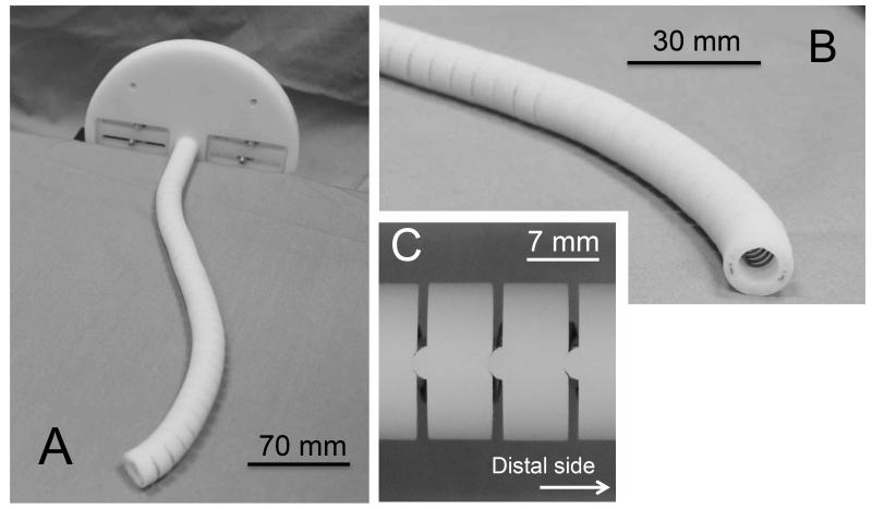
We measured the friction coefficient in equation (10), by preparing two sets of wires and eyelets for measurement. The first set comprised 2:1 scale wires and a test piece with eyelets made with the same machining approach as the robot. The wire ropes consisted of three 0.1-mm-diameter strands of super-elastic NiTi. The net diameter of the tendon wire was 0.23 mm. The test pieces were made of stainless steel with a 3.4-mm diameter and 0.3-mm-diameter eyelets. The eyelets were machined by drilling and beveling the edges. The second set comprised wires and wire guides for a 10:1 scale prototype described further in the posture validation section below (Fig. 9). The wire ropes (3423T21, McMaster-Carr) consisted of 7×7 strand cores of clear fluorinated ethylene-propylene (FEP). Their outer diameter was 0.53 mm. The wire guides were made of acrylonitrile butadiene styrene copolymer (ABS) of 14 mm with 1.0-mm-diameter eyelets. The guides were machined by rapid-prototyping technology.
Fig. 9.
10:1 scale prototype. A, Perspective view; B, Enlarged view of the tip; C, Enlarged view of the hinges in the wire guides.
The wire threaded the eyelet in the test piece with both edges fixed on the experimental apparatus. The test piece was slanted by manual rotational stage until slipping on the wire. We measured this slip angle and determined the friction coefficient as the tangent of the slip angle.
We performed 18 measurements with the 2:1 scale test pieces and 30 measurements with the 10:1 scale wire guides. The data are summarized as mean ± SD (standard deviation).
The value of the friction coefficient (Table II) was determined as 0.31 for use in (10) in the FKM for a performance analysis of the robot. We also used 0.33 as the value of μ for posture validation of the 10:1 scale prototype to generate a prediction of postures and wire pull by the FKM.
TABLE II.
Measured Friction Coefficient
| Friction
coefficient |
|||
|---|---|---|---|
| Material | n | Mean | SD |
| SUS, NiTi wire rope |
18 | 0.31 | 0.07 |
| ABS, FPE- coated wire rope |
30 | 0.33 | 0.03 |
B. Range of motion in 180°-angle and as 45°-angle view
We simulated and analyzed the motion range of the robot at the 180°-angle view as well as 45°-angle view. The 45°-angle view was chosen as additional condition to primary 180°-angle view, in this part of the study, as the 45°-angle view requires distinctively unique posture of robot in S-shape compared to the 180°-angle view does. The analysis was conducted in Mathematica computational software using the FKM with our measured friction coefficient μ. All data presented in this section were obtained using the calculated friction coefficient from the first experiment.
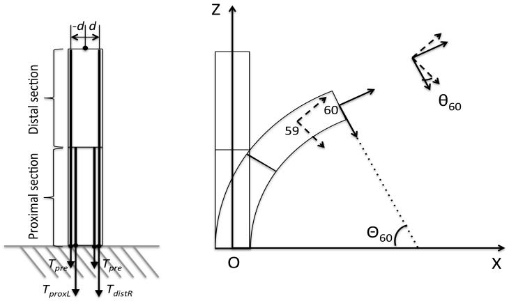
The coordinate system and notation of this analysis are shown in Fig. 6. We set the bending plane on the X-Z plane of the base coordinate system. The robot was grounded mechanically with the proximal end at (0,0). The tip angle was expressed as the angular displacement of cell 60 based on the base coordinate system Θ60. For the local curvature of the robot, the angular displacement of cell i based on cell (i − 1) θn was used.
Fig. 6.
Coordinate system and notation for performance analysis.
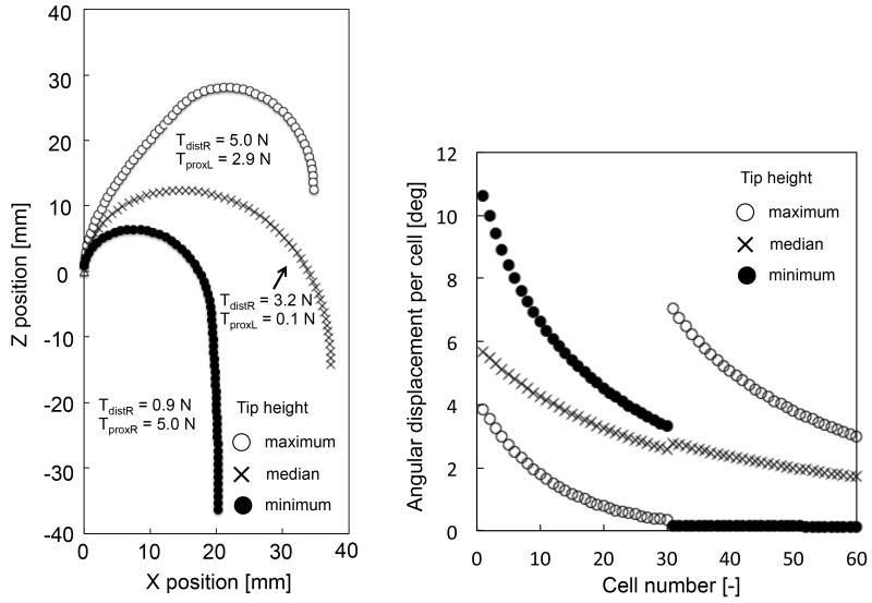
We also defined the tip position as a performance metric. We tabulated this metric at maximum, median, and minimal bending of the robot while maitaing the view angles. The details of the procedure for this analysis are as follows.
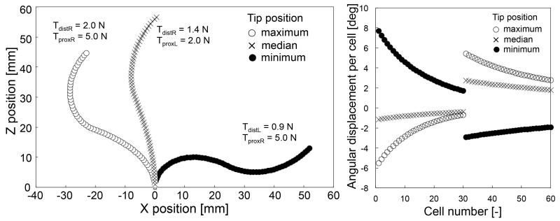
As the input of the FKM, we generated possible combinations of the tensions in the tendon wires (TproxL,TdistR) or (TproxR,TdistL) at intervals of 0.1 N. As pretension, there was a minimum value for the tension in the tendon wires of 0.1 N to avoid slack. By employing these combinations of the tensions in tendon wires in the FKM, we computed a corresponding group of postures for the robot. From this group, we selected postures with a tip angle of 180 degrees and 45 degrees.
Within the range of motion of the tip positions presented in Fig. 7 and 8, the robot could maintain the view angles (180 and 45 degrees). Fig. 7 and 8 also show the angular displacement per cell of the two-section robot. From the maximum bending posture, to the minimum, the angular displacement per cell in the distal section decreased while the angular displacement in the proximal section increased. These angular displacements dislocated the robot tip maintaining the view angles.
Fig. 7.
Simulation results of the 45°-angle view. (Left) Positions of all cells (Right) Angular displacement per cell.
Fig. 8.
Simulation results of the 180°-angle view. (Left) Positions of all cells, and (Right) Angular displacement per cell.
In this simulation, we assumed that the critical constraint is the tension limitation in tendons. As the robot with the tool channel is miniaturized, both the outer diameter and the wall thickness of the wire guides decrease. This reduces the diameter of the tendons embedded in the wire guides as well as the moment arm. The smaller diameter of the tendons with the shorter moment arm presents a challenge in generating the bending moment for articulation. This reduction feature motivated us to simulate the articulation performance with a realistic tension limitation. Our simulation study indicates that the mechanism we propose can perform tip positions at the 180°-angle view under the tension limitation of the tendons.
We simplified the modulus of elasticity of Super-elastic NiTi with 50 GPa, and used the calculated value for the bending stiffness of the robot. Since the Super-elastic NiTi tubes have a large variation due to fabrication, the bending stiffness of the robot probably changes after fabrication from this assumption in the simulation. We expect that when the robot is fabricated at the proposed size, the bending stiffness of the robot should be measured and subsequently calibrated using the measurement values.
The flexural rigidity of the tendons (or actuation wire ropes) in the robot is smaller than the bending stiffness of cells by at least one order. Therefore, our simulation probably included a position error on the order of 10 percent. Specifically, we expect the proximal section of the robot to have the maximum error since the proximal section includes six tendons in one cell. We also expect that this contribution of the flexural rigidity of the tendons can be cancelled out by the design of the backbone, where the backbone in the proximal section has a smaller bending stiffness than in the distal section.
C. Posture Validation with Tendon Displacement
To prove the concept of variability of tip position at an angle view using a physical prototype, we developed a 10:1 scale prototype of the two-section robot (Fig. 9) and performed a series of validation study to assess our FKM modeling. The prototype had an outer diameter of 14.6 mm, a length of 208 mm, and comprised two sections actuated manually by four tendon wires. The mechanical specifications of the prototype are listed in Table III. The prototype had a similar mechanical structure to that of a robot we will fabricate. Hinged wire guides made of ABS polymer were stacked with a coil spring as a backbone. The bending stiffness of one cell is 2.7 × 10⁻² Nm/rad, measured after fabrication.
TABLE III.
Mechanical Specifications of 10:1 Scale Prototype
| Mechanical Parameter | Value |
|---|---|
| Length of cell | 6.95 mm |
| Number of cells | 30* |
| Bending stiffness of cell | 2.7 × 10⁻² Nm/rad |
| Moment arm of tendons | 5.5 mm |
Total number of two sections. Proximal and distal sections have fifteen cells.
The 10:1 scale prototype was simulated and developed to test different tendon layouts and different numbers of bending sections. The size of the 10:1 scale prototype allows the reconfiguration of routing and fixing position of the tendons and numbers of wire guides by manual assembly. We performed all validations with the same prototype. This is helpful to avoid deviations of internal parameters of the prototype among validations with different settings. We also intended to avoid unnecessary disturbances like unpleasant surface finish on the guide structures while maintaining the scale of the prototype at a size that both machining and capability can handle reliably. A similar approach to prove functionality of the robot bridging the simulation study with the miniature robot and the experimental study with the scaled-up prototype was successful in a study on the steerable electrode array for cochlear implant surgery [25].
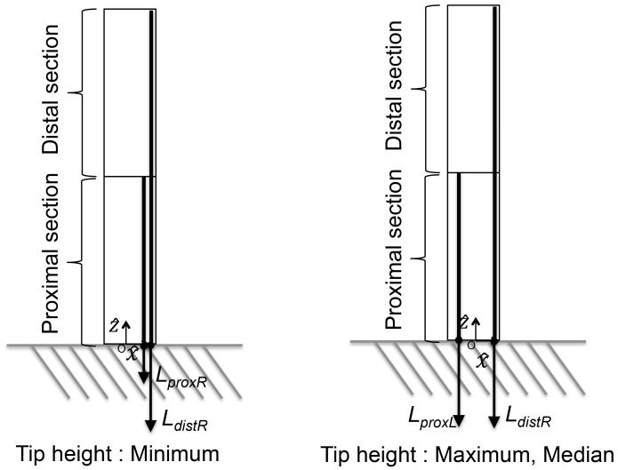
To verify whether the two-section robot could attain a variety of tip positions at a 180°-angle view, we operated the prototype to have three salient postures with different tip heights. Their locations are illustrated in Fig. 10, where one tendon is terminated on the proximal section and the other on the distal section.
Fig. 10.
Tendon locations for posture validation of the prototype.
For tendon displacement control, the wire pull was calculated by converting the simulated postures to the length of tendon wires by FKM at these postures. The input wire pull and number of measurements are listed in Table IV. The predicted values were computed by both FKM and PCCA with the same amount of wire pull for the experiment. Further, in this computation we used the same measured values for the bending stiffness, the moment arms, and the length of the bending sections between the two models.
TABLE IV.
Amount of Wire Pull for Postures of Three Tip Heights
| Amount of wire pull
(mm) |
|||||
|---|---|---|---|---|---|
| Tip height | n** | Ldist L | Ldist R | Lprox L | Lprox R |
| Maximum | 15 | N.A.* | 17.4 | −7.4† | N.A. * |
| Median | 15 | N.A.* | 17.4 | −5.0† | N.A. * |
| Minimum | 20 | N.A. * | 17.4 | N.A. * | 10.9 |
No wires
Negative value is amount of wire feeding.
The n column denotes the number of trials of bending action.
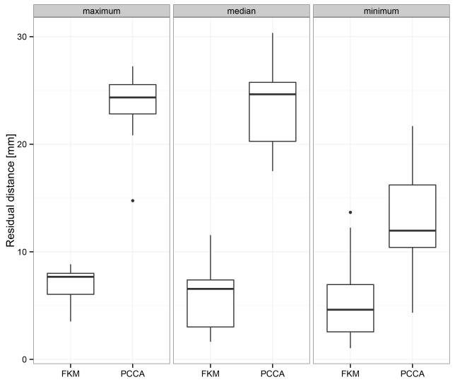
The prototype was placed on a plastic surface with a graph grid. The prototype was actuated manually from an initial (straight) posture to the targeted posture, and the wire pull was measured by a caliper. To measure the posture of the prototype, we acquired a digital still photograph with 0.09 mm-per-pixel resolution by a digital camera (EOS X6i, EF- S18-135 IS STM, Canon Inc.). We extracted the pixel position of the feature at the center of the wire guide for each cell from the photos. To determine the position with a physical metric scale, we converted these pixel position data to the metric ones based on pixel length of a known graph grid. We performed fifteen bending trials for the maximum and median tip heights and twenty bending trials for the minimum tip height. We recorded the posture once for every bending trial. The posture data are reported as mean ± 95% confidence interval. To determine if there were significant differences in prediction accuracy between the FKM we proposed and the conventional PCCA, we performed paired t-tests for tip-to-tip error (hereafter referred to as residual distance) of these two predictions for three tip heights. We considered differences to be statistically significant at P < 0.01.
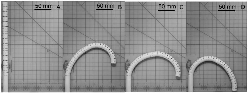
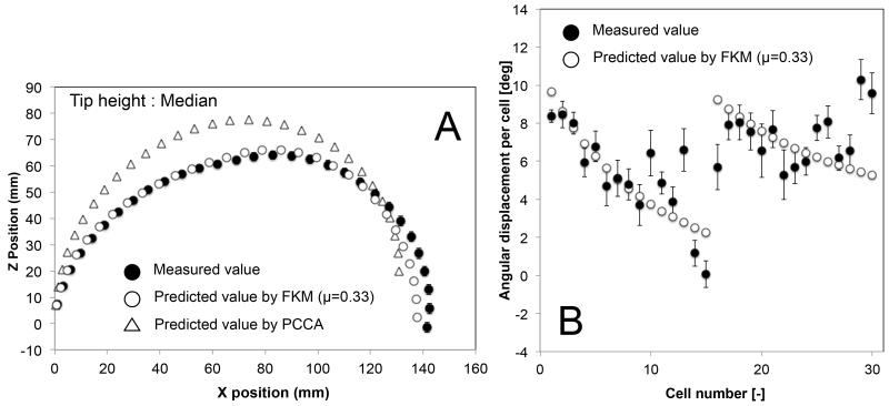
We validated the posture of the two-section prototype at the 180°-angle view (Fig. 11 A-D). The prototype performed a variety of tip heights, keeping tip direction at 180 degrees, by changing the curvature distribution between two sections. Fig. 11 shows three salient postures of maximum (11 B), median (11 C), and minimum (11 D) values of the tip height at the 180°-angle view.
Fig. 11.
Postures of 10:1 scale prototype at 180°-angle view. A, Initial straight posture; B, Maximum tip height; C, Median tip height; D, Minimum tip height.
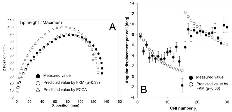
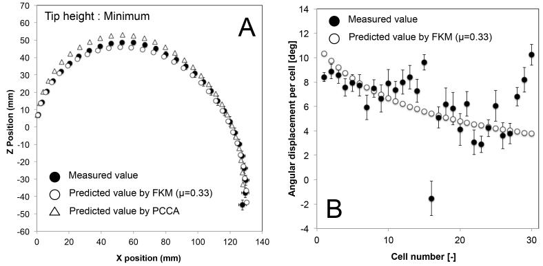
Figures 12, 13, and 14 show the mean position of each cell and the mean angular displacement per cell at the three tip heights. Error bars in the figures represent the 95% t-based confidence interval for each measurement in Table IV. Predicted values by the FKM (μ = 0.33) and the PCCA are plotted in these figures. The FKM predicted the mean position of each cell better than PCCA for all three tip heights. The mean angular displacement per cell was scattered by around 2 degrees at all tip heights. Mean values tended to be similar to the FKM-predicted values except for a few cells at the top of each section (i.e., cell numbers 10-15 and 25-30). These cells at the top of each section tended to have larger angular displacement than predicted values. Fig. 15 compares the residual distance of tip positions between the FKM and the PCCA. Paired t-tests indicated that the FKM predicted the tip position significantly better than the PCCA at all tip heights (P < 0.01).
Fig. 12.
Result of posture validation of 10:1 scale prototype at maximum tip height. A, Postures of robot grounded at (0,0) mechanically; B, Angular displacement per cell.
Fig. 13.
Result of posture validation of 10:1 scale prototype at median tip height. A, Postures of robot grounded at (0,0) mechanically; B, Angular displacement per cell.
Fig. 14.
Result of posture validation of 10:1 scale prototype at minimum tip height. A, Postures of robot grounded at (0,0) mechanically; B, Angular displacement per cell.
Fig. 15.
Comparison of the residual distance of the tip between predicted values and measurement values. Horizontal line represents median, and box represents interquartile range (IQR). Vertical line represents maximum/minimum datum or datum within 1.5 IQR.
D. Posture Validation with Tension Input
We performed articulation experiments with tension input to validate the mapping of the tension to the posture of the robot by the FKM. We observed the postures bending from the straight initial posture to the set point, inputting constant tension to tendons of the 10:1 scale prototype. To avoid inessential disturbances from the experimental setup, we tested the simplest configuration of the robot, i.e., one section of the robot with a single tendon or with an antagonistic pair of tendons.
To input constant tension stably, we used the weight of water to apply gravitational forces on tendons. Water bottles were hanged on the ends of tendons via idler pulleys to pull the tendons horizontally. We measured the friction losses from the bottom of the robot to the idler pulleys by using a digital force gage (Series 2 force gauge, Mark-10) on a linear slide stage (ZLW-1040, Igus), and calibrated the weight of water to apply correct target tension to the tendons, compensating for the measured friction losses of the experimental setup.
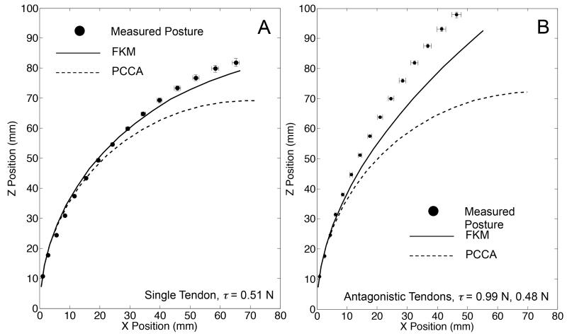
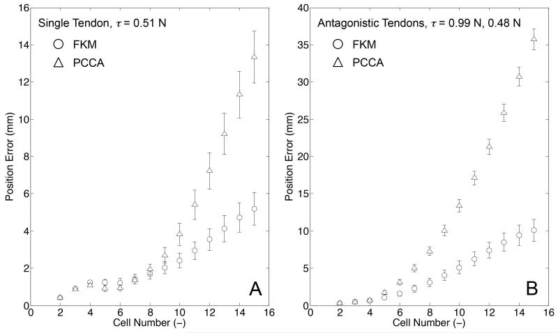
The one section of the 10:1 scale prototype was positioned with its bending plane aligned horizontally and placed on the flat surface of a polytetrafluoroethylene (PTFE) board. We observed the posture of the robot by using the same experimental setup as for the posture validation with tension displacement input. To identify the posture of the robot, we measured the position of fifteen hinges of the robot, and determined the position of fourteen cells by calculating middle points between adjoining hinges. We performed ten bending trials, and recorded the posture once for each bending trial. The independent variables were tendon layout in the robot and tension in tendons. The tendon layout was set to single tendon embedded on one side (+x direction from the centroid of the robot in Fig. 3) or to the antagonistic pair of tendons. The tension for the single tendon layout was set to 0.51 N. The tensions for the antagonistic pair of tendons were set to 0.99 N for the tendon embedded on the +x direction from the centroid of the robot and 0.48 N for the tendon on the other side. Under these tension settings, the FKM predicted different postures between the single tendon layout and the antagonistic tendon layout, while the PCCA predicted the same posture for both layouts. The predicted values were computed by both FKM and PCCA with the same tension input as in the experiment. Additionally, in this computation we used the same values for the bending stiffness, the moment arms, and the length of the bending sections between the two models. The measured postures of the robot were compared to the values predicted by the FKM and PCCA. We determined the position error between the measured and predicted values at each cell, and plotted the mean position error with standard error of ten trials for each posture measurement. The results of the posture validation are illustrated in Fig. 16. For the single-tendon layout (Fig. 16 A), FKM predicted a measured posture with the maximum position error of 5.1 mm. The values predicted by PCCA had a larger position error than for FKM and a maximum position error of 13.5 mm. For the antagonistic-tendons layout (Fig. 16 B), the position errors of FKM and PCCA increased over that of the single tendon layout. However, the maximum position error of FKM was smaller than for PCCA (10.1 mm by FKM vs. 35.7 mm by PCCA).
Fig. 16.
Result of posture validation with tension input. Error bars signify standard error of x and z positions among ten trials. A, Single-tendon layout: the measured postures (black circles) were performed with the tension of 0.51 N; B, Antagonistic-tendons layout: the measured postures (black circles) were performed with tension of 0.99 N in the tendon on the bending side of the robot and 0.48 N in the tendon on the extending side of the robot.
Fig. 17 shows the results of the position error between the measured and predicted values at each cell. The position errors in the single tendon layout increased from the proximal to the distal cell in the robot and the distal cell of the robot had the maximum error (5.1 mm by FKM vs. 13.5 mm by PCCA). In the antagonistic tendons layout, the position error also increased from the proximal to the distal cell. The maximum position error of FKM was smaller than for PCCA (10.1 mm by FKM vs. 35.7 mm by PCCA).
Fig. 17.
Result of position error. A, Single-tendon layout; B, Antagonistictendons layout. The position error of FKM (circles) and PCCA (triangles) are plotted. The error bars signify a standard error among ten trials.
E. Proof-of-concept 2:1 Scale Model
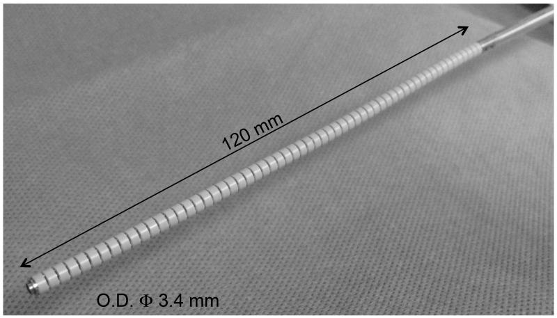
We developed a 2:1 scale prototype to confirm the feasibility of the FKM in a more miniature scale (Fig. 18). The 2:1 scale prototype has an outer diameter of 3.4 mm and a section length of 60 mm; it comprises two sections. A preliminary experiment with one section was conducted to investigate the tip-to-tip error at a tip angle of 90 degrees. We found that the error of the FKM was smaller than for the PCCA (0.5 mm by FKM vs. 7.6 mm by PCCA). Our visual observation confirms that the prototype, in general, follows the motion model generated by the FKM.
Fig. 18.
2:1 scale prototype
V. DISCUSSIONS AND CONCLUSIONS
In this study, we proposed a multi-section continuum robot to make wide-angle visualization and flexible positioning of the distal tip possible. In the performance analysis by the FKM, the two-section robot can achieve a range of motion suitable for intra-cranial observation in neuroendoscope while maintaining 180° -angle view and 45° -angle view. Following this performance analysis, we confirmed the salient postures with different tip positions at a 180°-angle view by developing a 10:1 scale prototype. We also experimentally evaluated the posture by tension control, and compared the position error between measured and predicted values by FKM and PCCA. Our results indicate that FKM helps to increase the prediction accuracy for the posture of the robot with both a single-tendon and an antagonistic-tendons layout.
In the posture validation with tension input, FKM tended to predict larger bending angles for a set of cells of the robot than the measured values, though FKM improved prediction accuracy over PCCA. This tendency was predominant in the antagonistic-tendons layout. Therefore, the discrepancy between FKM-predicted and measured values probably results from the friction effect at the hinges of the wire guides, which FKM does not consider. Since the hinges of the 10:1 scale prototype contact adjoining hinges with convex and concave structures, a slipping motion of the hinges might produce a larger friction effect than would rolling friction without a slipping motion. The antagonistic-tendons layout pressed the wire guides with larger force than the single-tendon layout and increased this friction effect. We expect that the mechanical design of the hinges to suppress the slipping motion is helpful to reduce this unpleasant friction effect and to develop the robot with suitable control.
The major limitation of surgical clipping is the lack of appropriate visualization to identify sensitive brain tissue and cranial nerves, producing increased morbidity and mortality. It is important to visualize the brain tissue around the aneurysm, especially in the posterior communicating artery, choroidal artery, or one of the distal cerebral arteries, to avoid any damage that can cause loss of neurological and motor functions. This typically requires an endoscope capable of complex maneuvers (such as an S shape) with multiple sections of bending and varying bending radii and angles. Commercially available fiber-bundle neuro-endoscopes are not capable of this functionality. Such a neuro-endoscope is expected to enable the surgeon to clearly identify critical anatomy in the brain, access deep-seated aneurysms, and evaluate surgical clip placement.
Our device is not limited for use in neuro-endoscopic manipulation but can be extended to other endoscopes. Breedveld et al. proposed a 6 DOF steerable laparoscope using a parallelogram-mechanism to transform the handgrip movements into tip motion [26]. Goldman et al. proposed a telerobotic system for transurethral surveillance and surgical intervention [15], extending their unique approach of a multi-backbone mechanism originally proposed for Thoracoscopy [27]. Lastly, Desai et al. extended a commercial robotic catheter (Hansen Medical, Inc. Mountain View, CA), originally developed for endocardial ablation, for arrhythmia, but modified it for use with flexible ureterorenoscopy for high-dexterity control [28]. Our study and these prior arts share the common but unmet clinical needs in endoscopy where clinicians need to direct the endoscope to a specific lesion to maintain the best endoscopic observation for a prolonged time. Our approach, however, differs from others; we can control individual curvature of subsections in the endoscope to form arbitrary shapes of the endoscope, rather than aiming to place the tip of the endoscope to a specific location with no control over the shape of the whole endoscope. It is expected that our approach can provide safer postures of endoscopes by avoiding critical anatomical structures, and its benefit is not limited to neuro-endoscopes.
In summary, we have shown that a two-section continuum robot has the advantage of flexible positioning of the tip at angle-view tasks over conventional one-section endoscopes. This feature of the two-section robot can expand use of the endoscope to inspect around or behind aneurysms without displacing neurovascular structures.
ACKNOWLEDGMENTS
NH is a member of the Board of Directors of AZE Technology and has an equity interest in the company. AZE Technology develops and sells imaging technology and software. NH’s interests were reviewed and are managed by the Brigham and Women’s Hospital and Partners HealthCare in accordance with their conflict of interest policies.
This work was supported in part by Canon USA Inc. and in part by the National Institutes of Health under Award Number P41EB015898, P01CA067165, R01CA138586, R01CA111288, R01CA124377 and R42CA137886.
Biographies
Takahisa Kato received the B.S. and M.S. in mechanical engineering from the Keio University in 1997 and 1999. He is currently a senior scientist of Healthcare Optics Research Laboratory in Canon USA Inc. He has more than ten years experience in designing and fabricating Micro Electro Mechanical Systems. His research interests include design, control and clinical implementation of miniature biomedical devices.
Ichiro Okumura received masters degree in mechanical engineering from the Tokyo Institute of Technology in 1977. He has developed several Ultrasonic Motors for camera lenses. He received the Technology Award from the Japan Society of Mechanical Engineers in 1992. He is developing new mechanisms of a continuum robot for endoscopic surgery in the research and development division of Canon Inc.
Sang-Eun Song received the M.Sc. degree in mechanical systems engineering from the University of Liverpool, U.K., in 2000, and the Ph.D. degree in mechanical engineering (medical robotics) from Imperial College London, U.K. in 2005. He is currently a Research Associate in the School of Engineering and Applied Sciences at Harvard University. His research interests include design, control, and clinical implementation of surgical robots and biomedical devices.
Alexandra J. Golby is a practicing neurosurgeon and translational investigator developing advanced image guided neurosurgery. She received her BA from Yale University and MD from Stanford University. Dr. Golby is Associate Professor of Neurosurgery and Radiology at Harvard Medical School and Associate Neurosurgeon at Brigham and Women’s Hospital. She leads the BWH effort in image-guided neurosurgery as the neurosurgery core leader for the National Center for Image Guided Therapy and clinical co-director of the Advanced Multi-modality Image-Guided OR at BWH.
Nobuhiko Hata received the B.E. degree in precision machinery engineering in 1993 from The University of Tokyo, Tokyo, Japan, and the M.E. and the Doctor of Engineering degrees in 1995 and 1998 respectively, both from The University of Tokyo, Tokyo, Japan. He is currently an Associate Professor of Radiology, Harvard Medical School and Brigham and Womens Hospital. In the Image Guided Therapy Program and Surgical Navigation and Robotics Laboratory at Brigham and Womens Hospital, he leads research team on medical image processing and robotics in image-guided surgery. His major achievements include neurosurgical navigation combined with ultrasound imaging, surgical robot for magnetic resonance imager, and motion-adaptable surgical robot for image-guided therapy.
Contributor Information
Takahisa Kato, National Center for Image Guided Therapy, Brigham and Women’s Hospital and Harvard Medical School, MA, USA (kato@bwh.harvard.edu); Healthcare Optics Research Laboratory, Canon U.S.A., Inc., MA, USA (takato@cusa.canon.com).
Ichiro Okumura, Advanced Systems R&D Center, Canon Inc., Japan. (okumura.ichiro@canon.co.jp).
Sang-Eun Song, National Center for Image Guided Therapy, Brigham and Women’s Hospital and Harvard Medical School, MA, USA (sam@bwh.harvard.edu).
Alexandra J. Golby, Department of Neurosurgery, Brigham and Women’s Hospital, Harvard Medical School, MA USA (agolby@partners.org).
Nobuhiko Hata, National Center for Image Guided Therapy, Brigham and Women’s Hospital and Harvard Medical School, MA, USA (nhata@partners.org).
REFERENCES
- [1].Schievink WI. Medical progress - intracranial aneurysms. NEW ENGLAND JOURNAL OF MEDICINE. 1997 Jan;336(1):28–40. doi: 10.1056/NEJM199701023360106. [DOI] [PubMed] [Google Scholar]
- [2].Fischer G, Oertel J, Perneczky A. Endoscopy in aneurysm surgery. NEUROSURGERY. 2012 Jun;70(6):184–190. doi: 10.1227/NEU.0b013e3182376a36. [DOI] [PubMed] [Google Scholar]
- [3].Taniguchi M, Kato A, Taki T, Tsuzuki T, Yoshimine T, Kohmura E. Microsurgical maneuvers under side-viewing endoscope in the treatment of skull base lesions. SKULL BASE-AN INTERDISCIPLINARY APPROACH. 2011 Mar;21(2):115–121. doi: 10.1055/s-0031-1275248. [DOI] [PMC free article] [PubMed] [Google Scholar]
- [4].Camarillo DB, Milne CF, Carlson CR, Zinn MR, Salisbury JK. Mechanics modeling of tendon-driven continuum manipulators. IEEE TRANSACTIONS ON ROBOTICS. 2008 Dec;24(6):1262–1273. [Google Scholar]
- [5].Camarillo DB, Carlson CR, Salisbury JK. Configuration tracking for continuum manipulators with coupled tendon drive. IEEE TRANSACTIONS ON ROBOTICS. 2009 Aug;25(4):798–808. [Google Scholar]
- [6].Hannan MW, Walker ID. Kinematics and the implementation of an elephant’s trunk manipulator and other continuum style robots. JOURNAL OF ROBOTIC SYSTEMS. 2003 Feb;20(2):45–63. doi: 10.1002/rob.10070. [DOI] [PubMed] [Google Scholar]
- [7].Jones BA, Walker ID. Kinematics for multisection continuum robots. IEEE TRANSACTIONS ON ROBOTICS. 2006 Feb;22(1):43–55. [Google Scholar]
- [8].Webster RJ, Romano JM, Cowan NJ. Mechanics of precurved-tube continuum robots. IEEE TRANSACTIONS ON ROBOTICS. 2009 Feb;25(1):67–78. [Google Scholar]
- [9].Dupont PE, Lock J, Itkowitz B, Butler E. Design and control of concentric-tube robots. IEEE TRANSACTIONS ON ROBOTICS. 2010 Apr;26(2):209–225. doi: 10.1109/TRO.2009.2035740. [DOI] [PMC free article] [PubMed] [Google Scholar]
- [10].Simaan N, Taylor R, Flint P. A dexterous system for laryngeal surgery; IEEE International Conference on Robotics and Automation ICRA; NEW YORK: IEEE. 2004.pp. 351–357. [Google Scholar]
- [11].Xu K, Simaan N. Analytic formulation for kinematics, statics, and shape restoration of multibackbone continuum robots via elliptic integrals. JOURNAL OF MECHANISMS AND ROBOTICS-TRANSACTIONS OF THE ASME. 2010 Feb;2(1):011006. [Google Scholar]
- [12].Burgner J, Rucker DC, Gilbert HB, Swaney PJ, Russell PT, III, Weaver KD, Webster RJ., III A telerobotic system for transnasal surgery. IEEE-ASME TRANSACTIONS ON MECHATRONICS. 2014 Jun;19(3):996–1006. doi: 10.1109/TMECH.2013.2265804. [DOI] [PMC free article] [PubMed] [Google Scholar]
- [13].Butler EJ, Hammond-Oakley R, Chawarski S, Gosline AH, Codd P, Anor T, Madsen JR, Dupont PE, Lock J. Robotic neuro-endoscope with concentric tube augmentation; IEEE International Conference on Intelligent Robots and Systems; NEW YORK: IEEE. 2012; pp. 2941–2946. [DOI] [PMC free article] [PubMed] [Google Scholar]
- [14].Ding J, Goldman RE, Xu K, Allen PK, Fowler DL, Simaan N. Design and coordination kinematics of an insertable robotic effectors platform for single-port access surgery. IEEE-ASME TRANSACTIONS ON MECHATRONICS. 2013 Oct;18(5):1612–1624. doi: 10.1109/TMECH.2012.2209671. [DOI] [PMC free article] [PubMed] [Google Scholar]
- [15].Goldman RE, Bajo A, MacLachlan LS, Pickens R, Herrell SD, Simaan N. Design and performance evaluation of a minimally invasive telerobotic platform for transurethral surveillance and intervention. IEEE TRANSACTIONS ON BIOMEDICAL ENGINEERING. 2013 Apr;60(4):918–925. doi: 10.1109/TBME.2012.2226031. [DOI] [PubMed] [Google Scholar]
- [16].Kutzer MDM, Segreti SM, Brown CY, Taylor RH, Mears SC, Armand M. Design of a new cable-driven manipulator with a large open lumen: Preliminary applications in the minimally-invasive removal of osteolysis; 2011 IEEE INTERNATIONAL CONFERENCE ON ROBOTICS AND AUTOMATION (ICRA); 2011. [Google Scholar]
- [17].Peirs J, Reynaerts D, Van Brussel H, De Gersem G, Tang H. Design of an advanced tool guiding system for robotic surgery; 2003 IEEE INTERNATIONAL CONFERENCE ON ROBOTICS AND AUTOMATION, VOLS 1-3, PROCEEDINGS; 2003.pp. 2651–2656. [Google Scholar]
- [18].Zuo S, Yamanaka N, Sato I, Masamune K, Liao H, Matsumiya K, Dohi T. Mri-compatible rigid and flexible outer sheath device with pneumatic locking mechanism for minimally invasive surgery; 4th International Workshop on Medical Imaging and Augmented Reality; Univ Tokyo, Tokyo, JAPAN. AUG 01-02, 2008.2008. pp. 210–219. [Google Scholar]
- [19].STURGES R, LAOWATTANA S. A flexible, tendon-controlled device for endoscopy. INTERNATIONAL JOURNAL OF ROBOTICS RESEARCH. 1993 Apr;12(2):121–131. [Google Scholar]
- [20].Zhang J, Simaan N. Design of underactuated steerable electrode arrays for optimal insertions. JOURNAL OF MECHANISMS AND ROBOTICS-TRANSACTIONS OF THE ASME. 2013 Feb;5(1) [Google Scholar]
- [21].Agrawal V, Peine WJ, Yao B. Modeling of transmission characteristics across a cable-conduit system. IEEE TRANSACTIONS ON ROBOTICS. 2010 Oct;26(5):914–924. [Google Scholar]
- [22].Palli G, Borghesan G, Melchiorri C. Modeling, identification, and control of tendon-based actuation systems. IEEE TRANSACTIONS ON ROBOTICS. 2012 Apr;28(2):277–290. [Google Scholar]
- [23].Webster RJ, Jones BA. Design and kinematic modeling of constant curvature continuum robots: A review. INTERNATIONAL JOURNAL OF ROBOTICS RESEARCH. 2010 Nov;29(13):1661–1683. [Google Scholar]
- [24].Xu K, Simaan N. An investigation of the intrinsic force sensing capabilities of continuum robots. IEEE TRANSACTIONS ON ROBOTICS. 2008 Jun;24(3):576–587. [Google Scholar]
- [25].Zhang J, Roland JT, Jr., Manolidis S, Simaan N. Optimal path planning for robotic insertion of steerable electrode arrays in cochlear implant surgery. JOURNAL OF MEDICAL DEVICES-TRANSACTIONS OF THE ASME. 2009 Mar;3(1) [Google Scholar]
- [26].Breedveld P, Hirose S. Design of steerable endoscopes to improve the visual perception of depth during laparoscopic surgery. JOURNAL OF MECHANICAL DESIGN. 2004;126(1):2–5. [Google Scholar]
- [27].Simaan N, Xu K, Wei W, Kapoor A, Kazanzides P, Taylor R, Flint P. Design and integration of a telerobotic system for minimally invasive surgery of the throat. INTERNATIONAL JOURNAL OF ROBOTIC RESEARCH. 2009;28(9) doi: 10.1177/0278364908104278. [DOI] [PMC free article] [PubMed] [Google Scholar]
- [28].Desai MM, Grover R, Aron M, Ganpule A, Joshi SS, Desai MR, Gill IS. Robotic flexible ureteroscopy for renal calculi: Initial clinical experience. JOURNAL OF UROLOGY. 2011;186(2):563–568. doi: 10.1016/j.juro.2011.03.128. [DOI] [PubMed] [Google Scholar]


