Abstract
Objective:
The aim of this study was to investigate the influence of implant crown splinting and the use of angulated abutment on stress distribution in implant body and surrounding bone by three-dimensional finite element analysis.
Materials and Methods:
For this study, three models with two implants at the site of mandibular right second premolar and first molar were designed (1): Both implants, parallel to adjacent teeth, with straight abutments (2): Anterior implant with 15 mesial angulations and posterior implant were placed parallel to adjacent tooth, (3): Both implants with 15 mesial angulations and parallel to each other with 15° angulated abutments. Restorations were modeled in two shapes (splinted and nonsplinted). Loading in tripod manner as each point 50 N and totally 300 N was applied. Stress distribution in relation to splinting or nonsplinting restorations and angulations was done with ABAQUS6.13.
Results:
Splinting the restorations in all situations, led to lower stresses in all implant bodies, cortical bone and spongy bone except for the spongy bone around angulated first molar. Angulated implant in nonsplinted restoration cause lower stresses in implant body and bone but in splinted models more stresses were seen in implant body in comparison with straight abutment (model 2). Stresses in nonsplinted and splinted restorations in cortical bone of angulated molar region were more than what was observed in straight molar implant (model 3).
Conclusion:
Implant restorations splinting lead to a better distribution of stresses in implant bodies and bone in comparison with nonsplinted restorations, especially when the load is applied off center to implant body. Angulations of implant can reduce stresses when the application of the load is in the same direction as the implant angulation.
Keywords: Angulated abutment, dental implant, finite element analysis
INTRODUCTION
Implant support prosthesis has become a routine dental treatment. To achieve the best outcome, careful consideration of technical and biomechanical parameters, is essential.[1]
The aims of splinting implant restorations are to the better distribution of applied forces to the implants, to reduce the transfer of nonaxial load to the bone-implant interface and to maximize the bone surface area. The resistant and retentive forms of implant restorations are other causes of restorations splinting.[2]
There are a few human clinical studies to confirm that implant restoration splinting has a better long-term effect than nonsplinting.[3,4] Guichet et al.[3] in a photo elastic study reported that splinted restorations lead to more constant distribution of stress between the implants when nonaxial forces are applied to restorations. Wang et al.[4] in a three-dimensional finite element analysis (FEA) showed that the splinting of adjacent implant restoration together results in less peri-implant stress when horizontal forces were applied to the poor quality bone.
On the other hand, Naert et al.[5] in a prospective clinical study investigated the result of implant restorations splinting in the treatment of partial edentulism. They reported that there was no significant difference in hazard rate between single implant crowns and splinted implant restorations. In another clinical study, the same group of authors found that marginal bone loss around splinted and nonsplinted implant restoration had no difference in partially edentulous patients.[6] In regard to controversies in the effect of implant restoration splinting, more studies seem to be needed. However, implants restoring as independent units haves many advantages, such as good interproximal hygiene and ability to replace or repair porcelain fracture or chipping.[2]
In an ideal situation, in order to achieve the best stress distribution, implants must be inserted parallel to each other and to the adjacent teeth[7,8] but such condition does not always exist[8,9] for example residual ridge resorption can lead to the proximity of anatomical structures to implant placement location.[10,11] In this situation, implants may be inserted into angulations with each other or the adjacent teeth. So, clinicians have to use angulated abutments to overcome this problem.[7,8,9,12,13] The effects of implants angulations and angulated abutment in stress distribution in supporting bone and implants bodies are suspected.[14,15,16]
In several studies, it has been showed that the use of angled abutments leads to more stress on the implant and surrounding bone.[17,18,19] Clelland et al.[17] evaluated the stress distribution in bone with the use of three angulated abutments in an FEA study. They concluded that the increase in abutments angulations increased the magnitude of stresses. Watanabe et al.[20] in an FEA study compared single straight implants with 45° angulated implants. In their study, stresses in the bone increased with implant angle inclination.
Although some studies have shown that angulated abutments did not have a determinable adverse effect on clinical success rates.[7,8,9,12,13] Sethi et al.[7] performed a 5 years prospective study and found that angulated abutments may be used without any influence on the long-term implant survival. Martini et al.[21] in evaluating the influence of Loading on Bone Stress by three-dimensional (3D) FEA concluded that implants with straight abutments generated the highest stress values in bone in comparison with angulated abutments.
The findings from Satoh et al.[22] showed that mesial tilting (10–20°) of implants to maintain them in a position perpendicular to the anteroposterior curve, does not lead to increased stress in the bone.
Due to the controversies in the use of the splinting of single implant supported restorations and the influence of angulated abutments on induced stress in the implants and bones, this study is designed to evaluate the effect of implant splinting and angulations on stress magnitudes in implants and surrounded bones.
MATERIALS AND METHODS
In this study, in edentulous region of right second premolar and first molar a dentate prefabricated mandibular model, two fixture analogs (Biohoraizons Internal, Implant system Inc., Birmingham, Al, USA) 4, 10.5 mm, with 4.5 mm diameter abutment platform with 3 mm distance to each other were embedded parallel to each other by dental surveyor.
The 3D geometry of the model, fixture, a straight abutment and a 15° angulated abutment (6 mm height, Biohoraizons) were scanned and digitized using scanning technology (SolutionixRexcan III).
Abutments were fastened to fixtures analogs on the model and then a Ni-Cr (Verabound-II, AalbaDent, Inc., CA, USA) casting coping in 0.5 mm thickness was fabricated. The coping was scanned. Porcelain (VITA Zahnfabrik, Bad Sackingen, Germany) veneering was applied to a standard method with 1 mm thickness and then was scanned. The whole system and components were scanned using Atos II (triple scan) scanning technology (GOM mbH, Braunschweig, Germany) and Atos reviewer v 6.3 software (GOM, Germany). Computer modeling was done in the manner of dense points cloud using of CATIA modeling software (V5R20, BM, Kingstone, NY, USA).
In modeling, the cortical bone thickness was reproduced in 2 mm layer and spongy bone was defined at its center. Implants were considered totally osseointegrated. Other contacts existing between the elements were also assumed to be perfect. The geometries were then meshed by tetrahedral linear elements.
Three-dimensional finite element models were simulated in these manners:
Two implants in 3 mm distance from each other and parallel to adjacent teeth, with straight abutments (4.5 mm of platform diameter, 6 mm height) [Figure 1]
The anterior implant was inserted with 15° mesial angulations, and the posterior implant was placed parallel to an adjacent tooth. A 15° angulated abutment was placed on the anterior implant and a straight abutment was inserted into posterior implant [Figure 2]
Two implants with 15° mesial angulations and parallel to each other with 15° angulated abutments [Figure 3].
Figure 1.
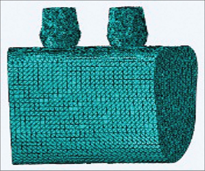
Two straight implants
Figure 2.
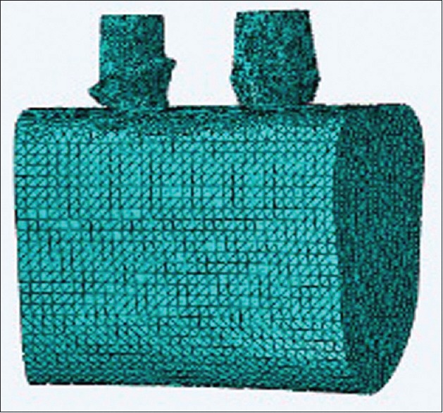
15° angulated premolar implant and molar straight implant
Figure 3.
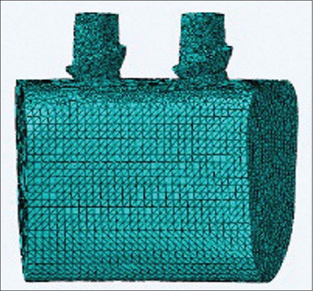
Two 15° angulated implants
Restorations were simulated in two models (splinted and nonsplinted) [Figures 4 and 5]. Meshed models consisted of 509,124 nodes and 2,685,847 elements with a little difference in models.
Figure 4.
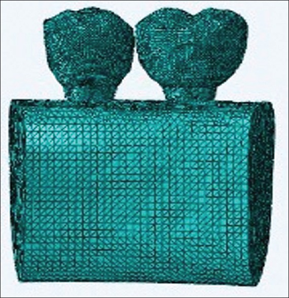
Non splinted restorations
Figure 5.
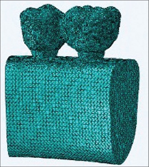
Splinted restorations
In the models, an arbitrary 300 N vertical load in tripod manner (each point 50 N) was applied to distal fossa of the second premolar and central fossa of first molar[23] [Figure 6]. The value of friction coefficient was fixed to 0.02[24] [Figure 6].
Figure 6.
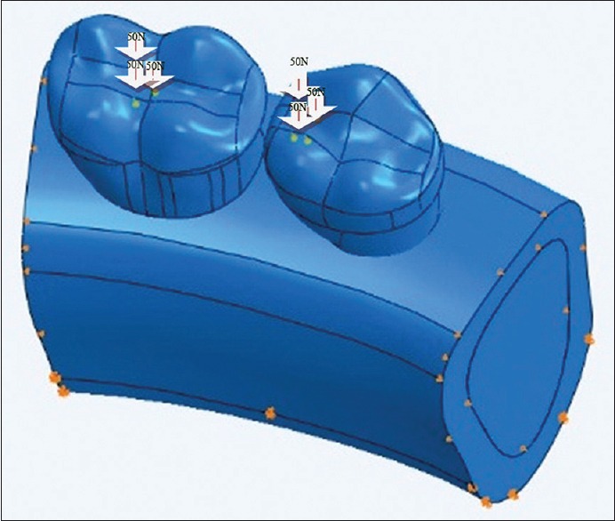
Tripod loading
Stress distribution was evaluated in relation of splinting or nonsplinting restorations and angulations. Stress analysis of models was done with ABAQUS6.13.
Materials properties that were used in this study are summarized in Table 1.
Table 1.
Materials properties

RESULTS
Maximum stress values in 6 models are summarized in Tables 2–4.
Table 2.
S, Mises stress magnitudes (MPa) in implant body, cortical and spongy bone after loading of splinted and nonsplinted restorations with straight abutments

Table 4.
S, Mises stresses magnitudes (MPa) in implant body, cortical and spongy bone after loading of splinted and nonsplinted restorations with 15° angulated abutments

Table 3.
S, Mises stresses magnitudes (MPa) in implant body, cortical and spongy bone after loading of splinted and nonsplinted restorations with straight abutment in molar site and 15° angulated abutment in premolar site

Maximum stress values in splinted restorations of straight abutments (model 1) were lower than nonsplinted restorations (model 2) [Figures 7–10].
Figure 7.
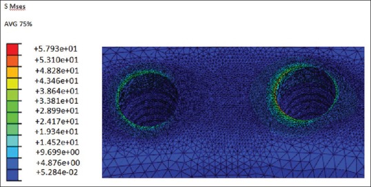
S, Mses stress magnitudes (M Pa) in bone (two straight nonsplinted implants)
Figure 10.
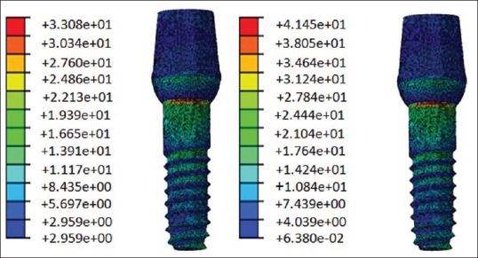
S, Mses stress magnitudes (M Pa) in implant body (straight splinted implants), premolar implant in left side and molar implant in right side
Figure 8.
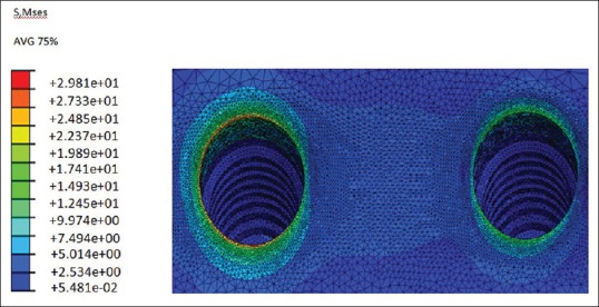
S, Mses stress magnitudes (M Pa) in bone (2 straight splinted implants)
Figure 9.
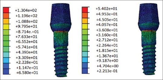
S, Mses stress magnitudes (M Pa) in implant body, (straight non splinted implants), premolar implant in left side and molar implant in right side
Maximum stress values in the straight implant body (130.4 Mpa) and it is surrounded cortical bone in premolar site (57.93) were more than other sites and another models.
In third model maximum stress value of cortical bone around angulated premolar implant in splinted simulation was more than straight position (21.41 Mpa) [Figures 11–14].
Figure 11.
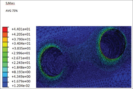
S, Mses stress magnitudes (M Pa) in bone (straight and angulated nonsplinted implants)
Figure 14.
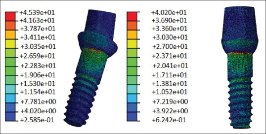
S, Mses stress magnitudes (M Pa) in implant body (straight and angulated splinted implants) pre molar implant in left side and molar implant in right side
Figure 12.
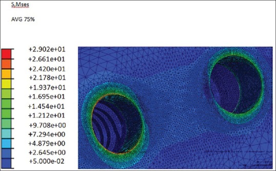
S, Mses stress magnitudes (M Pa) in bone (straight and angulated splinted implants
Figure 13.
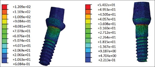
S, Mses stress magnitudes (M Pa) in implant body (straight and angulated nonsplinted implants) pre molar implant in left side and molar implant in right side
In fifth and sixth model angulated molar implant showed higher stress values in splinted (37.23 Mpa) and nonsplinted (43.71 Mpa) simulations in surrounded cortical bone compare to a straight position [Figures 15–18].
Figure 15.
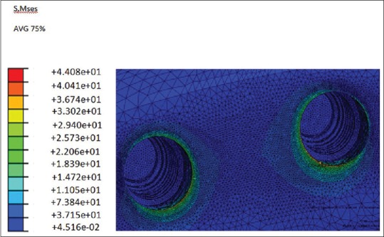
S, Mses stress magnitudes (M Pa) in bone (two angulated nonsplinted implants)
Figure 18.
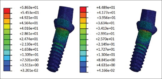
S, Mses stress in implant body (two angulated splinted implants) pre molar implant in left side and molar implant in right side
Figure 16.
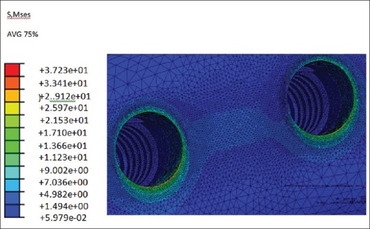
S, Mses stress in bone (two angulated splinted implants)
Figure 17.
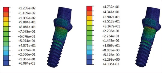
S, Mses stress in implant body (two angulated nonsplinted implants), pre molar implant in left side and molar implant in right side
Splinting the restorations in all models decreased the maximum stress values. Results also show that magnitudes of stress in cortical bone are more than spongy bone.
DISCUSSION
A dental implant serves to accept the physiologic loads or forces into the surrounding tissues. The resultant force per unit area can lead to remodeling of bone. Therefore, the manner in which implants distribute stress in interfacial tissues is an important factor. Analyzing force transfer at the bone-implant interface is an essential step, which determines the success or failure of an implant. Overload can cause bone resorption or fatigue failure of the implant.[25]
Splinting of adjacent implants is recommended to reduce the transfer of horizontal forces to the bone, for the better distribution of stress in bone and prevention of screw loosening in abutments. The increase of retention and resistance are other reasons for splinting the restorations.[2] The transference of the occlusal forces to the bone implant interface is an important factor in the implant treatment successfulness.[26] However, some studies have indicated that splinting has no adverse effect on the long-term success of implant restorations. Naert et al.[5] reported no significant increasing hazard rate for single crowns in comparison with splinted fix prosthesis in a 16 years clinical follow-up. In another clinical study, Naert et al.[6] reported, that the amount of marginal bone loss around single and splinted implant restorations was equal. In a meta-analysis of patients who were treated with fixed partial dentures and single unit implant restorations, there was no significant difference in survival rate between them.[27]
In this study, the splinting of the restorations in all positions, led to lower stress in all implant bodies, cortical bone, and spongy bone except for the spongy bone around angulated first molar. These results indicate that splinting is beneficial to reduce stress in implant body and cortical bone, especially when the load is applied off-center to implant body. In this study, three-point loadings were applied to the central fossa of the first molar and distal fossa of the second premolar as is observed in a healthy dentition. Although the applied loads were vertical, the suffering area in the premolar was off center to the implant body and therefore resulted in cantilever load on the premolar in comparison with the first molar in which the loads were applied exactly along the center of the implant body. So it can be said that the load application site is an important factor. The off-center loading on premolar produced more stress in second premolar than in the molar region.
Splinting reduced the stress in premolar more than it did in the molar region. This may be due to the fact that splinting has led to the reduction of cantilever forces on the implant and bone around the premolar site.
The reduction of stress magnitude observed in this study is in agreement with the findings of Guichet et al.[3] They reported when eccentric forces were applied to implant restorations, splinting helped the more even stress distribution among the implants.
The results of this study are also similar to the findings of Wang et al.[4] in evaluating the effect of splinting in stress distribution in poor quality bone, as they concluded splinting was effective in reducing stress in the bone.
The angulation of the implant is one of the most important factors in the management of the stress peri-implants structures. The behavior of bone in the peri-implant region is closely related to the direction, magnitude and concentration of stresses transmitted to the implant.[28]
Angulated abutments are used in some clinical situations, such as nonparallel implant. Some implants due to bone deficiency or fault of surgery may be inserted in angulations to adjacent implant or tooth.[8,9] In order to correct this condition, angulated abutments have been introduced.[7,8,9,12,13]
In some studies, the use of angulated abutment led to more stress in the supportive crestal bone of the implant. Clellend et al.[17] in an FEA study reported more stress and strain while increasing angulations of the abutment was observed. Lin et al.[16] found that by increasing the abutment angulations, the amount of strain in implant and cortical bone could be higher.
According to Geng, et al.[25] several FEA studies of osseointegrated implants demonstrated that maximum stress concentration is located at the cortical bone crest. In cortical bone, stress dissipation is restricted to the immediate surroundings of the implant, whereas in the trabecular bone a fairly broader distant stress distribution occurs.
In the present study, the use of angulated abutments in premolar site resulted in lower stress in the cortical bone and implant body of nonsplinted restoration which is similar to the findings of Tian et al.[29] FEA study. They found that angulated abutment results in less amount of stress on implant supporting bone. Sethi et al.[7] in a 5 years a prospective case study on 2261 implants, found that angulated abutments may be used with no influence on long-term survival rate.
In this study, the angulation of premolar implant was toward the mesial and the load was applied to the distal fossa. So, the angulations of the implant may lead to the reduction of the cantilever stress in comparison with a straight implant.
In comparison with straight implants, the amount of stress increased in the premolar angulated implant body and the bone around it in splinted restorations. This may be due to the effect of the direction of angulations. So, the proximity of the premolar implant apex to the molar implant led to more transferred stresses to the premolar implant and the bone around it.
When both implants and abutment were angulated, the amount of stress in nonsplinted restorations was more in implant body, cortical bone and spongy bone than in the splinted model. In nonsplinted restorations, molar implant body experienced less stress while in the cortical bone more stress was compared to the splinted model. Because of the angulation of the molar implant, the applying loads on central fossa induced less stress in implant body and forces were distributed in the cortical bone in comparison with a straight molar implant.
Almost in all positions, stress in the cortical bone around the molar implant was lower than in the premolar site. This may be due to the location of load application and also the size of the molar crown. The bigger surface area receiving the force in the molar crown in comparison to the premolar crown with similar force could lead to force distribution in a larger area. So the molar implant receives less force.
CONCLUSION
The following conclusions were drawn from the present study:
Implant restorations splinting lead to the better distribution of stress causing lower stress in implant body and bone in compression with nonsplinted restorations, especially when the load is applied on the off center of the implant body
Angulations of the implant can reduce cantilever forces when the applied load is in the same direction of implant angulation.
Footnotes
Source of Support: Nil.
Conflict of Interest: None declared
REFERENCES
- 1.Feitosa PC, de Lima AP, Silva-Concílio LR, Brandt WC, Neves AC. Stability of external and internal implant connections after a fatigue test. Eur J Dent. 2013;7:267–71. doi: 10.4103/1305-7456.115407. [DOI] [PMC free article] [PubMed] [Google Scholar]
- 2.Grossmann Y, Finger IM, Block MS. Indications for splinting implant restorations. J Oral Maxillofac Surg. 2005;63:1642–52. doi: 10.1016/j.joms.2005.05.149. [DOI] [PubMed] [Google Scholar]
- 3.Guichet DL, Yoshinobu D, Caputo AA. Effect of splinting and interproximal contact tightness on load transfer by implant restorations. J Prosthet Dent. 2002;87:528–35. doi: 10.1067/mpr.2002.124589. [DOI] [PubMed] [Google Scholar]
- 4.Wang TM, Leu LJ, Wang J, Lin LD. Effects of prosthesis materials and prosthesis splinting on peri-implant bone stress around implants in poor-quality bone: A numeric analysis. Int J Oral Maxillofac Implants. 2002;17:231–7. [PubMed] [Google Scholar]
- 5.Naert I, Koutsikakis G, Duyck J, Quirynen M, Jacobs R, van Steenberghe D. Biologic outcome of implant-supported restorations in the treatment of partial edentulism. part I: A longitudinal clinical evaluation. Clin Oral Implants Res. 2002;13:381–9. doi: 10.1034/j.1600-0501.2002.130406.x. [DOI] [PubMed] [Google Scholar]
- 6.Naert I, Koutsikakis G, Quirynen M, Duyck J, van Steenberghe D, Jacobs R. Biologic outcome of implant-supported restorations in the treatment of partial edentulism. Part 2: A longitudinal radiographic study. Clin Oral Implants Res. 2002;13:390–5. doi: 10.1034/j.1600-0501.2002.130407.x. [DOI] [PubMed] [Google Scholar]
- 7.Sethi A, Kaus T, Sochor P. The use of angulated abutments in implant dentistry: Five-year clinical results of an ongoing prospective study. Int J Oral Maxillofac Implants. 2000;15:801–10. [PubMed] [Google Scholar]
- 8.Brown SD, Payne AG. Immediately restored single implants in the aesthetic zone of the maxilla using a novel design: 1-year report. Clin Oral Implants Res. 2011;22:445–54. doi: 10.1111/j.1600-0501.2010.02125.x. [DOI] [PubMed] [Google Scholar]
- 9.Eger DE, Gunsolley JC, Feldman S. Comparison of angled and standard abutments and their effect on clinical outcomes: A preliminary report. Int J Oral Maxillofac Implants. 2000;15:819–23. [PubMed] [Google Scholar]
- 10.Graziani F, Donos N, Needleman I, Gabriele M, Tonetti M. Comparison of implant survival following sinus floor augmentation procedures with implants placed in pristine posterior maxillary bone: A systematic review. Clin Oral Implants Res. 2004;15:677–82. doi: 10.1111/j.1600-0501.2004.01116.x. [DOI] [PubMed] [Google Scholar]
- 11.Basa S, Varol A, Turker N. Alternative bone expansion technique for immediate placement of implants in the edentulous posterior mandibular ridge: A clinical report. Int J Oral Maxillofac Implants. 2004;19:554–8. [PubMed] [Google Scholar]
- 12.Sethi A, Kaus T, Sochor P, Axmann-Krcmar D, Chanavaz M. Evolution of the concept of angulated abutments in implant dentistry: 14-year clinical data. Implant Dent. 2002;11:41–51. doi: 10.1097/00008505-200201000-00013. [DOI] [PubMed] [Google Scholar]
- 13.Dubois G, Daas M, Bonnet AS, Lipinski P. Biomechanical study of a prosthetic solution based on an angled abutment: Case of upper lateral incisor. Med Eng Phys. 2007;29:989–98. doi: 10.1016/j.medengphy.2006.10.017. [DOI] [PubMed] [Google Scholar]
- 14.Saab XE, Griggs JA, Powers JM, Engelmeier RL. Effect of abutment angulation on the strain on the bone around an implant in the anterior maxilla: A finite element study. J Prosthet Dent. 2007;97:85–92. doi: 10.1016/j.prosdent.2006.12.002. [DOI] [PubMed] [Google Scholar]
- 15.Hasan I, Röger B, Heinemann F, Keilig L, Bourauel C. Influence of abutment design on the success of immediately loaded dental implants: Experimental and numerical studies. Med Eng Phys. 2012;34:817–25. doi: 10.1016/j.medengphy.2011.09.023. [DOI] [PubMed] [Google Scholar]
- 16.Lin CL, Wang JC, Ramp LC, Liu PR. Biomechanical response of implant systems placed in the maxillary posterior region under various conditions of angulation, bone density, and loading. Int J Oral Maxillofac Implants. 2008;23:57–64. [PubMed] [Google Scholar]
- 17.Clelland NL, Lee JK, Bimbenet OC, Brantley WA. A three-dimensional finite element stress analysis of angled abutments for an implant placed in the anterior maxilla. J Prosthodont. 1995;4:95–100. doi: 10.1111/j.1532-849x.1995.tb00323.x. [DOI] [PubMed] [Google Scholar]
- 18.Kao HC, Gung YW, Chung TF, Hsu ML. The influence of abutment angulation on micromotion level for immediately loaded dental implants: A 3-D finite element analysis. Int J Oral Maxillofac Implants. 2008;23:623–30. [PubMed] [Google Scholar]
- 19.Cavallaro J, Jr, Greenstein G. Angled implant abutments: A practical application of available knowledge. J Am Dent Assoc. 2011;142:150–8. doi: 10.14219/jada.archive.2011.0057. [DOI] [PubMed] [Google Scholar]
- 20.Watanabe F, Hata Y, Komatsu S, Ramos TC, Fukuda H. Finite element analysis of the influence of implant inclination, loading position, and load direction on stress distribution. Odontology. 2003;91:31–6. doi: 10.1007/s10266-003-0029-7. [DOI] [PubMed] [Google Scholar]
- 21.Martini AP, Freitas AC, Jr, Rocha EP, de Almeida EO, Anchieta RB, Kina S, et al. Straight and angulated abutments in platform switching: Influence of loading on bone stress by three-dimensional finite element analysis. J Craniofac Surg. 2012;23:415–8. doi: 10.1097/SCS.0b013e31824b9c17. [DOI] [PubMed] [Google Scholar]
- 22.Satoh T, Maeda Y, Komiyama Y. Biomechanical rationale for intentionally inclined implants in the posterior mandible using 3D finite element analysis. Int J Oral Maxillofac Implants. 2005;20:533–9. [PubMed] [Google Scholar]
- 23.Sevimay M, Usumez A, Eskitascioglu G. The influence of various occlusal materials on stresses transferred to implant-supported prostheses and supporting bone: A finite element analysis. J Biomed Mater Res. 2005;73:140–7. doi: 10.1002/jbm.b.30191. [DOI] [PubMed] [Google Scholar]
- 24.Nickel JC, McLachlan KR. In vitro measurement of the frictional properties of the temporomandibular joint disc. Arch Oral Biol. 1994;39:323–31. doi: 10.1016/0003-9969(94)90124-4. [DOI] [PubMed] [Google Scholar]
- 25.Geng J, Yan W, Xu W. E book. Berlin: Springer; 2008. Application of the Finite Element Method in Implant Dentistry. [Google Scholar]
- 26.Moreira W, Hermann C, Pereira JT, Balbinoti JA, Tiossi R. A three-dimensional finite element study on the stress distribution pattern of two prosthetic abutments for external hexagon implants. Eur J Dent. 2013;7:484–91. doi: 10.4103/1305-7456.120642. [DOI] [PMC free article] [PubMed] [Google Scholar]
- 27.Lindh T, Gunne J, Tillberg A, Molin M. A meta-analysis of implants in partial edentulism. Clin Oral Implants Res. 1998;9:80–90. doi: 10.1034/j.1600-0501.1998.090203.x. [DOI] [PubMed] [Google Scholar]
- 28.Canay S, Hersek N, Akpinar I, Asik Z. Comparison of stress distribution around vertical and angled implants with finite-element analysis. Quintessence Int. 1996;27:591–8. [PubMed] [Google Scholar]
- 29.Tian K, Chen J, Han L, Yang J, Huang W, Wu D. Angled abutments result in increased or decreased stress on surrounding bone of single-unit dental implants: A finite element analysis. Med Eng Phys. 2012;34:1526–31. doi: 10.1016/j.medengphy.2012.10.003. [DOI] [PubMed] [Google Scholar]


