Abstract
We perform rapid spontaneous Raman 2D imaging in light-sheet microscopy using continuous wave lasers and interferometric tunable filters. By angularly tuning the filter, the cut-on/off edge transitions are scanned along the excited Stokes wavelengths. This allows obtaining cumulative intensity profiles of the scanned vibrational bands, which are recorded on image stacks; resembling a spectral version of the knife-edge technique to measure intensity profiles. A further differentiation of the stack retrieves the Raman spectra at each pixel of the image which inherits the 3D resolution of the host light sheet system. We demonstrate this technique using solvent solutions and composites of polystyrene beads and lipid droplets immersed in agar and by imaging the C–H (2800-3100cm−1) region in a C. elegans worm. The image acquisition time results in 4 orders of magnitude faster than confocal point scanning Raman systems, allowing the possibility of performing fast spontaneous Raman·3D-imaging on biological samples.
OCIS codes: (170.3880) Medical and biological imaging; (180.5655) Raman microscopy; (300.6450) Spectroscopy, Raman; (110.4234) Multispectral and hyperspectral imaging
1. Introduction
Noninvasive imaging techniques capable of recording rapid tomographic images with good spatial resolution and chemical contrast are of great interest in biology and medicine for the study of development and functioning of cells and tissues. Confocal micro-Raman based systems are able of obtaining optical sectioning using the label-free contrast mechanism intrinsically induced by the molecules contained in the sample [1]; however, due to the very low efficiency of the spontaneously emitted Raman signal (1 in 108 incident photons is Raman-shifted [2]), the long image acquisition time (normally from a few seconds to several hours) makes it unsuitable for studying most of the dynamic processes of living micro-organisms. To exploit the benefits of the chemical contrast of the Raman effect, novel microscopic techniques based on nonlinear coherent anti-Stokes Raman scattering (CARS) or Stimulated Raman Scattering (SRS) processes have emerged providing high detection sensitivity, fast imaging speeds and intrinsic confocal capabilities [3–6]. Despite that, the optical systems involved are usually complex to be implemented and the richness of the full Raman spectral information is commonly limited by the wavelength tuning range (or bandwidth) of the ultrashort pulse laser sources used; which can be expensive. In this sense, cost-effective SRS imaging has been implemented using a pair of continuous wave (cw) lasers [7, 8] which are more stable, easy to operate and can be used in combination with fluorescence imaging. However, the SRS signal is induced via a Raman gain (or loss) process at one of the available wavelengths of the two sources [4, 6–8]; therefore, a fast modulation and lock-in based detection should be implemented to detect the SRS signal. As this is based on a point detection scheme, a laser scanning system is normally used. Additionally, the acquisition time relays on the shot noise level, the frequency of modulation and on the lock-in integration time. Finally, in SRS to obtain full Raman spectra, the Stokes laser has to be tunable over the Stokes wavelengths. This adds complexity to the imaging system.
Recently, light sheet (LiSh) fluorescence microscopy has emerged as a powerful technique for in vivo time lapse studies on single cells, whole organisms and tissues [9–11]. Due to this geometry, LiSh illumination via selective plane illumination microscopy (SPIM) or digital scanned light sheet microscopy (DSLM), provides intrinsic optical sectioning capabilities (of large fields of view) in which photodamage is greatly reduced (due to the restriction of the irradiation to the plane under observation) while at the same time, the signal collection is performed in a very efficient way. These two characteristics result in enhanced sample viability. Besides, because the excitation and collection branches are uncoupled, the resolution in the transversal and axial directions are determined by the numerical aperture (NA) of the collection objective and by the light-sheet thickness, respectively.
In this context, although it is well known that Raman scattered signals from cells and tissues are extremely weak, the combination of an efficient (plane) excitation with an also efficient light signal collection results in a highly promising scheme for obtaining fast full-2D images using the spontaneous Raman signal as contrast mechanism. Recently, using a custom-made spectrograph in a SPIM configuration, Barman et. al. [12] demonstrated the possibility of performing optically sectioned Raman imaging on 20 μm polystyrene beads. In this case, the 50 µm × 150 µm images were taken at a single vibrational Raman frequency and the acquisition time was of 2 minutes each. Similarly, Oshima et. al. [13], performed Raman SPIM on zebra fish acquiring 2.3 mm × 2.3 mm images at different vibrational Raman bands using a tunable Ti:sapphire laser in the cw-mode; the image acquisition time was about 10 seconds each. Unfortunately, in both cases, a full Raman spectrum was not acquired.
An alternative for fast Raman was demonstrated by Hamada et. al. [14] using a line-shaped cw-laser as the Raman excitation and imaging it (in a confocal configuration) at the entrance slit of a spectrophotometer equipped with a CCD detector. The authors performed hyperspectral Raman imaging on living HeLa cells at 185 sec/frame with the full Raman spectral information. However, in this case the acquisition time is limited by both the sample scanning and the CCD integration time to collect the Raman signal; which is affected by the typical losses occurring through the spectrometer optics and the critical confocal alignment.
To our knowledge a DSLM configuration has not been explored so far to perform wide-field spontaneous Raman imaging. Using a DSLM for Raman imaging instead of using a SPIM configuration could be advantageous because, similarly to the case of fluorescence imaging [11], results in a better excitation efficiency as the full power of the excitation light is concentrated into the single scanned line; and in a more homogenous light-sheet, where the height can be easily controlled with the amplitude of the scanning.
Under a LiSh configuration, instead of measuring the Raman signal in a point-by-point or line-by-line fashion, the full image at once can be spectrally resolved using an interferometric tunable filter (ITF). As it will be demonstrated here, by changing the angle of incidence of the ITF, the sharp edged transition in the transmittance is continuously shifted. This allows recording a cumulative intensity distribution of the vibrational bands on each pixel of the DSLM image as the ITF angular position is changed. Then, similarly to the knife-edge technique used to measure beam intensity profiles, a simple differentiation of the images is enough to recover the Raman spectrum. Importantly, such procedure can be easily applied to every pixel of the image, obtaining thus a high resolution 2D spectrally resolved Raman image.
In this work, we demonstrate how the use of a single compact CW laser in combination with a DSLM scheme, in which the detection is spectrally filtered using an ITF, results in a cost effective technique to perform rapid high-resolution spontaneous Raman 3D imaging. The proof of principle of the technique is shown using organic solvents and the feasibility of the technique for imaging solid 3D samples is demonstrated using a composition of polystyrene beads and lipid droplets immersed in agar. Additionally, the potential use of the technique for studying biological living samples is also demonstrated using spontaneous Raman imaging in the C–H (2600-3200cm−1) specific region as widely used in CARS and SRS microscopy [3–6, 15].
2. Knife-edge technique for spectral measurements
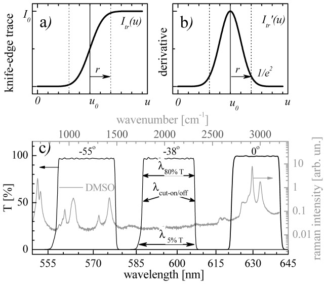
The knife-edge (KE) method is a standard technique used commonly to measure transversal intensity profiles of laser beams [16–18]. It consists on recording the laser intensity while a sharp knife (typically a razor blade) is translated perpendicular to the beam propagation using a calibrated translation stage; as a result of this “eclipsing process” the cumulative distribution intensity (i.e. the integral) of the beam is traced. Since the resulting trace does not replicate by itself the beam profile, a proper data inversion method needs to be used to finally obtain the beam intensity profile [19–21]. Figures 1(a), 1(b) show a computed fitting of a KE trace and its respective differential curve to retrieve a Gaussian beam profile. The measured KE traces, , of Gaussian beams are fitted with the sigmoid-shaped function [17, 20, 21]:
| (1) |
where is the total (unblocked) beam intensity, is the fitted center of plot, and r is the radius of a Gaussian beam at (see Fig. 1(b)). The independent variable is given typically in microns units while erf corresponds to the error function (or in other words, the integral of a Gaussian beam) [16, 19, 21]. Positive or negative sign of the erf trace is used depending on the experiment when the blade is moved to unblock or block the beam, respectively. Therefore, the magnitude of the derivative with respect the displacement in the KE trace, , results in the measured Gaussian beam profile.
Fig. 1.
a) Computed gaussian erf function and b) derivative commonly used on KE experiments for beam intensity profile characterization; r is the beam radius of the measured beam. C) spectral KE technique for Raman spectra extraction, λcut-on/off are the edge transitions. The black curves correspond to the transmittance of aused ITF (Semrock TBP01-628/14) at 0°, −38 o and −55° while the Raman spectrum (gray curve) corresponds to DMSO.
To characterize non-Gaussian beam profiles a direct differentiation of the measured KE traces is performed [16, 17, 22, 23]. Here, we use this KE approach to retrieve the spontaneous Raman spectra from KE traces. The “spectral knife” is emulated with the sharp cut-on/off slope transition of commercially available angle-tuned thin-film ITF [24, 25]. Such filters have improved features which are ideal to implement the spectral KE technique. They are capable of maintaining sharp step edges, over a full range of incidence angles (from 0° to 60°) with high transmission, excellent out of band blocking, and essentially no (or little) depolarization artifacts. Figure 1(c) pictures the principle of the spectral KE technique when the angle of incidence is moved in a range from 0° to −55°. Despite the finite bandwidth transmittance, starting at −38° and tuning the cut-on and cut-off transitions toward lower and higher wavelengths, respectively, a wide range is covered (>80 nm) allowing the scanning of the Raman spectra over 2300 cm−1 wavenumbers from 1000 to 3200 cm−1. This spectral region contains peaks that are known to occur in biological samples, such as the ring breathing of phenylalanine (1000 cm−1), the CH2 deformation (1451 cm−1) and stretching modes (2850 cm−1, 2885 cm-1), the CH3 stretching mode (2935 cm-1) and Amide-I vibrational mode of peptide bonds (1660 cm−1).
The spectral resolution for this technique given in wavenumbers (in cm−1 units) is
| (2) |
where is the filter edge step transition, with as the wavelength at the 5% nominal transmittance for the “blocking” part and at 80% for the “full transmitting” wavelength, as shown in Fig. 1(c). The, cut-on/off wavelength, , is defined as the wavelength at the 50% of the maximum transmittance intensity and is given (in nm units) by [25]
| (3) |
where is the cut on/off wavelength at normal incidence, is the angle of incidence, and is a fitting parameter which depends on the effective index of refraction of the filter design.
The excited vibrational frequency for each angular position is calculated from the energy difference between incident and scattered photon using the expression,
| (4) |
where is the excitation wavelength, and is the Stokes wavelength, respectively (both given in nm units). Note from Eq. (2) that interferometric filters can be used as a “spectral knifes” because the step transition keeps small over the tuning range and the angle dependent cut-on/off wavelength falls within the scattered Raman wavelengths, i.e. .
Figure 2 shows the estimation of the spectral resolution for three typical laser wavelengths used in Raman experiments; the curves are calculated using Eq. (2) and considering constant the edge transition of . Note that the longer the Stokes wavelength, , the better the resolution is. When using a 532 nm laser source, the Stokes wavelengths range go from 565 to 640 nm, covering a vibrational frequency range from 1000 to 3200 cm−1 with an increasing spectral resolution that goes from 66 to 48 cm−1. Therefore, an improved resolution is expected for the same vibrational frequency range if longer excitation wavelengths are used (see Fig. 2). We choose working with 532 and 636 nm sources in our experiments to take advantage of the CMOS quantum efficiency which is >30% for the excited Raman wavelengths. Notice that the spectral resolution obtained with green and red lasers is good enough to resolve vibrational bands in the C-H region (2700-3200 cm−1) and that such region has been successfully exploited for biological studies on lipids and tissue using CARS and/or SRS nonlinear Raman imaging [4–6].
Fig. 2.
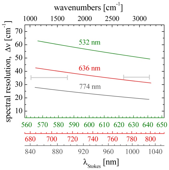
Estimation of the spectral resolution for three different Raman excitation laser sources (as indicated). Horizontal lines (in gray) indicate typical spectral regions of interests for Raman studies (see text).
Accessing the fingerprint region from 1000 to 1600 cm−1 would need the use of a near IR source and the Stokes wavelengths will falls between 840 to 900 nm. Although such region can be accessible using CCD/CMOS sensors its quantum efficiency would decrease from 20 to 10% compromising the image acquisition time.
3. Experiment
3.1. Raman LiShMS imaging setup
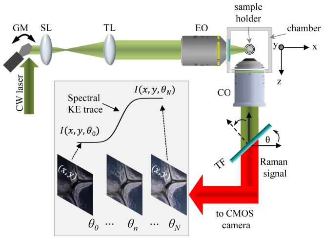
A detailed description of the optical setup to perform DSLM can be found elsewhere [11]. Here this system is briefly described in Fig. 3 to emphasize the required modifications to perform Raman light-sheet micro-spectroscopy (Raman LiShMS) imaging. In the figure the xy-plane is defined as the image plane (plane of interest) and the z-axis as the orthogonal direction where the Raman signal is to be collected. In order to generate the light sheet a CW laser beam is coupled to a galvanometric mirror (GM) that scans the beam along the xy-plane direction. The telescope arrangement, composed of a scanning lens (SL) and a tube lens (TL), is used to inject the scanned Gaussian beam at the rear focal plane of the excitation objective EO (10x , NA = 0.3, WD = 16 mm, Nikon, Japan) to create the light sheet at the sample plane. A custom made immersion chamber holds a capillary glass tube (Hirschman Z611263, 100 µl) where the samples are immersed. The capillary glass is attached to a motorized rotation stage (Physik instrument, M-116.2SH) and a xyz-motorized stage (3-axis NanoMax, Thorlabs) allowing full control of the experiments. An infinity corrected, water immersion collection objective (CO) (Leica/HCX Apo L20X, 0.5NA) is placed orthogonal to the sample plane, along the z direction to collect the spontaneous Raman scattered signal. After the CO an interferometric tunable filter, mounted on a high-precision rotation mount to vary the angle of incidence θ and thus tuning the filter pass band wavelength, is placed. A CMOS camera (Hamamatsu, ORCAFlash 4.0) is used to take the images while changing the angle of incidence to scan the filter transmittance. In that way, each pixel along the stack records a Raman spectral KE trace (see image inset).
Fig. 3.
Raman LiShMS imaging setup. CW: continuous wave; GM: x-y Galvo-Mirror; SL: Scanning Lens; TL: Tube Lens; EO: Exciting Objective; CO: Collecting Objective; TF: Tuning Filter; θ: tilt angle of the filter. Inset: Spectral knife edge (KE) trace extraction from a 2D image stack at a region of interest I(x,y) with N as the total number of images, each taken at a different filter tilt angle.
For our experiments two different CW laser, one at 532 nm (Verdi v10, Coherent) and another one at 638 nm (Cobolt, MLD), were used as excitation sources. After attenuating the 532 nm source (<50mW) a tuning filter TBP01-628/14 (Semrock) was used to filter the excited spontaneous Raman signal. A notch filter (Semrock, NF03-532E) and a pass band (Delta, BP 630/75) were also placed in front of the sCMOS sensor (not shown) to block the excitation wavelength. For the 632 nm source, a tuning filter TBP01-790/12(Semrock), was used. In this case a pair of pass band filters FF01-731/137 (Semrock) were used to block the excitation wavelength.
3.2. Micro-Raman measurements
In order to verify the Raman spectra taken under the proposed Raman LiShMS system, spectra of the studied samples are also acquired with a confocal micro-Raman system (inVia, Renishaw) in a backscattered configuration. The Raman excitation was performed with a 532 nm laser beam focused through a 50x, 0.75 NA air objective (Leica N Plan Epi). The power range used in our experiments is 2.5 mW allowing a spectra acquisition time of 10 seconds for the 500-3200 cm−1 vibrational frequency range. A typical resolution of 3 cm−1 is obtained using a 1800/mm grating.
4. Sample preparation
4.1. Solvent solutions
Glass micro-capillary tubes (Hirschmann Z611263, 100 μl) filled with Dimethyl Sulfoxide (DMSO) at 99.9% (Sigma, D8418), methanol (meth) at 70% and ethanol (eth) at 70% were used in our experiments. To prevent leakage and evaporation of the solutions the capillary tubes were fused at the bottom end and sealed with paper Parafilm (PM-996) at the top end. DMSO, methanol and ethanol solutions are typically used for characterizing Raman experiments because of their characteristic Raman vibrational bands in the so called fingerprint region (500-1600cm−1) as well as in the C-H region (2700-3000cm−1).
4.2. Lipofundin and polystyrene beads immersed in agar
In order to emulate 3D biological like samples a composite of 50um-sized polystyrene microspheres (Thermo scientific, 7550A) and lipofundin (MCT/LCT 20%, B. Braun) immersed in 1% low-melting agarose was prepared. The melted solution was deposited directly into a glass micro-capillary tube with a micropipette prior solidification. The end composite was slightly extruded out the capillary tube in order to be placed in front of the detection objective. We use the typical C-H Raman bands (2700-3000cm−1) of both the polystyrene and lipofundin for hyperspectral imaging.
4.3. Biological samples
To test the system for biological applications, we use the model organism Caenorhabditis elegans (C. elegans). Wild type C. elegans worms were routinely cultured in the laboratory on NGM plates at 20°C and fed on the non-pathogenic bacteria E.coli OP-50. Adults were picked and anesthetised with 5µl of sodium azide 35mM (Scharlab, Spain) for 10-15 min. Once immobilized, mixed with 1% low melting point agarose (Promega, Spain) at 30°C and injected with a micropipette in a 100µl glass micro-capillary.
5. Results and discussions
5.1. Tunable filters characterization
Due to the nonlinear dependence of the ITF with respect the angle of incidence, calibrating the filters prior the Raman imaging is essential to know the actual cut-on/off wavelength (and wavenumber) at a specific tilt angle θ, which is the same in magnitude as the angle of incidence (as can be deduced from Fig. 3). Figure 4 shows the calibration of the tunable Semrock filters TBP01-790/12 (a) and TBP01-628/14 (b) used for the red (636 nm) and green (532 nm) laser sources in our experiments, respectively. The measured cut-on and off wavelengths (as defined before and shown in Fig. 1c) are represented by open squares and open circles. Note that for the two used filters, a wide spectral range (>2000 cm−1) can be reached. It is worth also noting that the experimental data are in good agreement with the fitted curves (solid lines in Fig. 4) which are computed using Eq. (3) with values of nm, nm, and α = 1.775 for fitted curves of Fig. 4a, and nm, nm, and α = 1.875 for fitted curves of Fig. 4b, respectively.
Fig. 4.
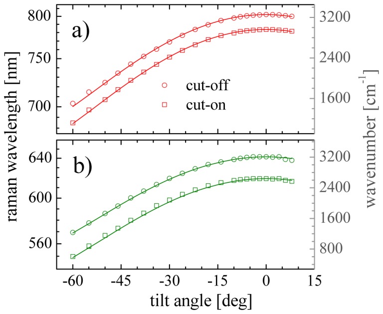
Filter tuning calibration for the two laser excitation sources used in the experiments at 636 nm (a) and 532 nm (b), respectively. Markers indicate the measured edge cut-on/off wavelength transition (as labeled) while solid lines are the fitted curves using Eq. (3).
5.2. Raman LiShMS proof of principle
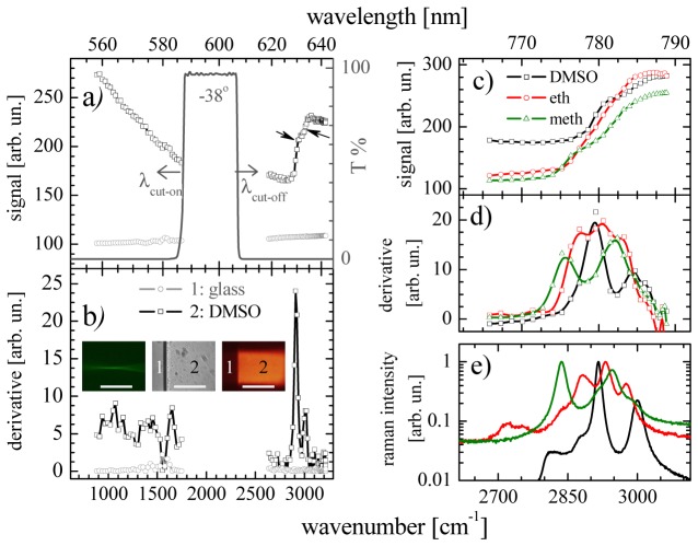
As a proof of principle demonstration, we proceeded to perform Raman light-sheet micro-spectroscopy using the spectral KE technique for three different solvents solutions (see Fig. 5). Here the green laser source is used at 15 mW, measured before the excitation objective. The transmission of the tunable filter at −38° of tilt angle is shown in Fig. 5(a), indicating the starting point of the wavelength tuning to perform the spectral KE technique over two different vibrational frequency ranges. By tilting the filter transmittance to the frequency range from 850 to 1750 cm−1 the left side sharp edge step (see cut-on wavelength) can be used for the scanned. Similarly, by tilting the transmittance the frequency range from 2600 to 3200 cm−1, the right side edge step (cut-off wavelength) can be used. Figure 5(b) shows the obtained KE traces for DMSO and glass in black squares and gray circles, respectively. The black arrows indicate two different inflexion points on the spectral KE trace of DMSO where the maxima of two vibrational bands are located. By a direct differentiation of the traces the DMSO, the Raman spectra is retrieved (Fig. 5(b)). The inset images in Fig. 5(b) from left to right corresponds to the (apertured) focused laser beam (elastic scattered light) of ~3 µm of diameter and a FOV of ~100 µm (data not shown). Figure 5(b) also shows the the cuvette glass/solution interface and the Raman light sheet. Each data point of Figs. 5(a) and 5(b) are the measured average intensity at the glass and DMSO regions (labeled as 1 and 2), respectively, for each specific tilt angle of the filter. A total of 100 angle positions (and so 2D images) are taken at 200 ms/frame, therefore the Raman spectrum shown takes only 21 seconds to be acquired. Note that such acquisition time is similar to the time a confocal Raman microscope commonly takes to complete a spectrum under the same irradiation conditions but only for a single point. Here instead of one single point, the spectra is taken from the whole 2D light sheet, resulting in 2D Raman images of 300 × 300 m2 at ~1 m/pixel, decreasing in this way the acquisition time by 4 orders of magnitude with respect a point scanning confocal Raman image.
Fig. 5.
Raman LiShMS imaging in different organic solvents. Spectral KE traces (a) and derivatives (b) of DMSO (black) and glass (gray) covering the 1000-3200 cm−1 vibrational frequency range. Laser source at 532 nm, 15 mW, and 200 ms acquisition time per image. Images in (b) are the focused laser beam (left), the cuvette glass/solution interface (center), and the Raman light sheet (right) of glass (1) and DMSO (2), respectively. Scale bar length is 150 µm. Spectral KE traces (c) and derivatives (d) of DMSO, ethanol, and methanol (as labeled) covering the 2600-3100 cm−1 frequency range. Laser source at 636 nm, 20 mW and 7.4 sec acquisition time per spectra. Raman spectra taken with a commercial micro-Raman equipment (e).
Note that for high frequencies (2600-3100 cm−1) the retrieved spectrum of Fig. 5(b) is in good agreement with the Raman spectrum shown in Fig. 1(c), taken with the micro-Raman equipment, however, at the low frequencies (850-1750 cm−1) the bands are poorly resolved. As already mentioned, the low spectral resolution obtained in such region is a drawback when using these two specific 532 and 632 nm excitation wavelengths (see Fig. 2). The use of longer excitation wavelengths in the 700-780 nm range, such as that obtained with CW Titanium-Sapphire oscillators, combined with tuning filters with improved step edges transmittance, would allow working in the fingerprint region. Although the signal of typical CMOS sensitivity is compromised due to the low quantum efficiency at the scattered Raman wavelengths (800-900 nm) it has been demonstrated that no damage is induced in cells when Raman experiments are conducted during 40 minutes of exposure using a 785 nm source at 115 mW with a 63x 0.9 NA objective [26]. An alternative way to extract the Raman molecular information from the low resolved spectra is applying modern deconvolution methods based on, for example, multivariate curve resolution (MCR) [27], which has been used to resolve multiple pure responses and concentrations of the Raman components present in unknown mixtures [28]. Here we are working in the CH stretching region where many molecular components share bands or are highly overlapped, thus the combination of the Raman LiShMS imaging technique here presented with MCR would enormously enhance the results and the chemical knowledge of the sample under analysis.
We therefore concentrate our study at the 2600-3200 cm−1 region where hydrogen (C–H and O–H) bonds are present and can be resolved with our current experimental setup. This was demonstrated for DMSO, methanol and ethanol, respectively (see Fig. 5(c)-5(d)). Here using the red (636 nm) laser source with 20 mW and recording only 25 angle positions, recording the Raman spectra in this region took 5 seconds. The retrieved spectra is shown in Fig. 5(d) and it is in good agreement with the Raman spectra taken with the confocal micro-Raman system shown Fig. 5(e), confirming the good spectral resolution obtained with the spectral KE technique.
5.3. Hyperspectral 3D-Raman imaging of polystyrene beads and lipids immersed in agar
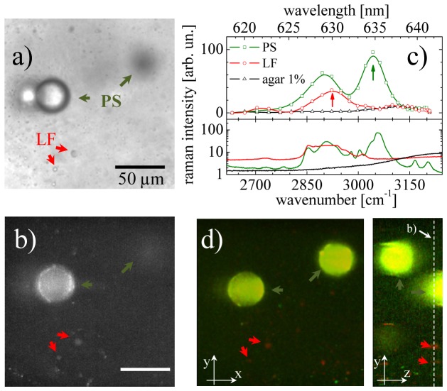
Figure 6 demonstrates the feasibility of the technique for optical sectioning and chemical contrast on 3D samples using a composite of polystyrene beads (55 μm in diameter) and lipid droplets immersed in agar at 1%. By comparing the wide-field image (Fig. 6(a)) with the single plane Raman image (Fig. 6(b)) the optical sectioning becomes evident. The wide-field image shows a significant amount of blurred structures coming from xy-planes outside the depth of field (~6 μm) of the used CO. On the other hand, LiSh image is formed by the scattered Raman signals coming only from the structures within the light-sheet thickness (~3μm) dictated by the lateral resolution (along z-axis) of the EO (see Fig. 3). Note that the Raman signal in Fig. 6(b) is extracted as taken from the spectral KE stack; that is, before computing the derivative and therefore no chemical contrast is observed yet in Fig. 6(b).
Fig. 6.
Optical sectioning and hyperspectral capabilities of Raman LiShM with tunable filters. a) Wide field image, b) single plane Raman image, c) Raman LiShM and Micro-Raman spectra, and d) hyperspectral image of samples composed of 50 µm polystyrene (PS) beads and lipofundine (LF) immersed in agar at 1%. Green and red arrows indicate PS beads and LF lipid droplets, respectively. The hyperspectral Raman LiShM image shown in (d) is the z-projection of a stack of merged images at the 2945 cm−1 and 3054 cm−1 Raman peaks (indicated with arrows in (c)). The transversal image reconstructed from the optically sectioned planes is shown in the inset image of (d). . Dashed line in (d) is the plane of image (b). Scale bar in b) is 50 µm
After calculating the derivative of the spectral KE stack, the spectral Raman information on each structure is retrieved. Figure 6(c) shows the obtained Raman spectra of polystyrene (PS) beads, lipofundine lipid droplets (LF), and water (1% agar), as labeled. The green and red arrows in Fig. 6 indicate the specific PS beads and LF droplets where the spectra are measured. It is worth mentioning that in order to minimize excitation power (to 20mW), the excitation wavelength was fixed at 532nm. This allowed us to exploit the high quantum efficiency of the CMOS camera. However, this also resulted in a compromising of the spectral resolution. Despite of that, the retrieved Raman spectra show good spectral resolution when compared with the micro-Raman spectra. Therefore, hyperspectral images can be obtained by merging the images at maximum peaks 2922 cm−1 and 3042 cm−1 of PS and LP spectra. The merged images for every optically sectioned plane at these two bands are restacked; resulting in 3D hyperspectral imaging showing the locations of PS and LF in green and red structures, respectively. Figure 6(d) shows the z-projection of all the hyperspectral images taken through 180 µm of depth. The inset shows the transversal image reconstructed from the optically sectioned planes separated 3 μm each. Note that the required time to extract all this 3D-Raman information (300 × 300 × 180 µm3) is just 5 minutes, approximately.
5.4. 3D-Raman imaging of C. elengans
Finally, Fig. 7 shows the potential use of Raman LiShMS imaging in biological living samples where the wide-field image (Fig. 7(a)) of C. elegans and PS beads immersed in agar at 1% is compared against the single plane non-spectrally resolved Raman image (Fig. 7(b)). It is worth mentioning that the PS beads are also included in order to have a Raman spectrum as a reference (although this is not necessary once the ITF are calibrated (see Fig. 4)). The arrows in Fig. 7(b) indicate the regions where the Raman spectra for the C. elegans and PS beads are retrieved. The top panel of Fig. 7(c) shows the Raman spectra (solid black curve) of the C.elegans worm obtained with the Raman LiShMS imaging system. After averaging the Raman signal coming from the whole region of the worm intestine, it is possible that the resulting shape in the spectrum can be a mixing of the Raman signal (coming from triacylglycerides) and of the auto-fluorescence (coming from lipid droplets) (see Fig. 1(d) in [29]). By normalizing the Raman signal with a fitted curve of the fluorescence signal the Raman bands become more evident (see dotted curve). The Raman spectrum of PS taken with LiShMS and confocal micro-Raman system are shown in the bottom graph of Fig. 7(c). Finally, Figs. 7(d) and 7(e) show the Raman images at the 2910 cm−1 y 2960 cm−1 peaks; indicating the presence of lipids and proteins/extracellular matrix, respectively. Note that the spatial resolution is low due to the 20x collection objective for the image formation used in our system; as a consequence the lipid spectra and morphology are not resolved for individual lipids. Nevertheless, the use of higher numerical apertures in the collection and higher power in the excitation will indeed increase and collect more efficiently the Raman signal enabling the spatial and spectral resolving of individual lipid structures.
Fig. 7.
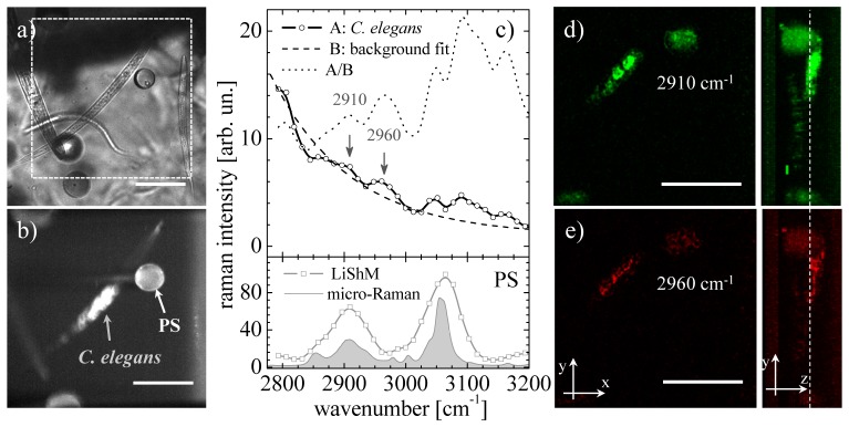
Raman LiShMS on C. elegans in agar at 1% with polystyrene beads as Raman markers. a) Wide field image, b) single plane Raman image, c) upper panel: Raman LiSh spectra coming from the intestine of the worm (solid black line), autofluorescente background (dashed line) and the ratio between these two spectra (dotted line); bottom panel: micro-Raman spectroscopy of PS taken with the LiSh system (gray line) and with a confocal Raman microspectrometer (Solid gray curve). d) spectrally resolved Raman images at 2910cm−1 and e) at 2960 cm−1, respectively. Scale bars are 100 µm. Dashed line in (e) is the plane of image in (b).
6. Conclusions
Using the advantages of a DSLM configuration for efficient excitation and signal collection we performed rapid 2D and 3D Raman light sheet micro-spectroscopy imaging. For that we used cw-lasers sources operating at 532 and 636 nm and having low irradiation powers (<50 mW) for Raman excitation. In addition, cost-effective interferometric tunable filters, instead of conventional spectrum analyzers, where used to retrieve the Raman spectra. To do that, the spectral knife-edge technique was proposed. Under the utilized excitation conditions, the obtained spectral resolution allowed identifying the high frequency C–H region (2600-3200cm−1); where important biological studies have been successfully performed using other novel nonlinear Raman imaging techniques. Importantly the time needed to analyze single 300 × 300 µm2 images at 1µm/pixel resolution is 4 orders of magnitude faster than in a conventional point scanning Raman imaging system. Based on the improved sensitivity and quantum efficiency of CMOS cameras and the laser damage threshold of cells, we predict that the KE technique would allow working with living cells in the fingerprint 1000-1700 cm−1 region if cw near IR excitation (in the 700-780 nm range) is used but at higher laser powers (50-120 mW) used in our experiments. The combination of DSLM and spectral KE techniques used in this work is extendible for multi fluorophore fluorescence imaging using broadband light sheet excitation and paves the way for exploring light-sheet non-linear CARS imaging using Bessel beams.
Acknowledgments
Authors would like to thank Dr. Eugenio Mendez for useful comments. IR-M acknowledges National Research and Technology Council of Mexico (CONACyT) for the short stay research grant for the consolidation of research groups supported (grant n. 233012). IR-M and JL-R also acknowledge funding support from CONACyT through grants n. 155803 and 238390, respectively. Authors also acknowledge the Laser Lab Europe (grant agreement no. 284464, EC's Seventh Framework Programme), the Photonics4Life network of excellence and the European regional Development Fund. This research has been partially supported by Fundació Cellex Barcelona and has been conducted at the super resolution light microscopy and nanoscopy facility at ICFO.
References and links
- 1.Dieing T., Hollricher O., Toporski J., “Confocal Raman Microscopy, Springer Series” in Optical Sciences 158 (Springer, 2011). [Google Scholar]
- 2.Long D. A., The Raman Effect: A Unified Treatment of the Theory of Raman Scattering by Molecules (John Wiley & Sons Ltd, 2002) [Google Scholar]
- 3.Rocha-Mendoza I., Langbein W., Borri P., “Coherent Antistokes Raman micro-spectroscopy using spectral focusing with glass dispersion,” Appl. Phys. Lett. 93(20), 201103 (2008). 10.1063/1.3028346 [DOI] [Google Scholar]
- 4.Min W., Freudiger C. W., Lu S., Xie X. S., “Coherent Nonlinear Optical Imaging: Beyond Fluorescence Microscopy,” Annu. Rev. Phys. Chem. 62(1), 507–530 (2011). 10.1146/annurev.physchem.012809.103512 [DOI] [PMC free article] [PubMed] [Google Scholar]
- 5.Zumbusch A., Langbein W., Borri P., “Nonlinear vibrational microscopy applied to lipid biology,” Prog. Lipid Res. 52(4), 615–632 (2013). 10.1016/j.plipres.2013.07.003 [DOI] [PubMed] [Google Scholar]
- 6.Alfonso-García A., Mittal R., Lee E. S., Potma E. O., “Biological imaging with coherent Raman scattering microscopy: a tutorial,” J. Biomed. Opt. 19(7), 071407 (2014). 10.1117/1.JBO.19.7.071407 [DOI] [PMC free article] [PubMed] [Google Scholar]
- 7.Meng Z., Petrov G. I., Yakovlev V. V., “Microscopic coherent Raman imaging using low-cost continuous wave lasers,” Laser Phys. Lett. 10(6), 065701 (2013). 10.1088/1612-2011/10/6/065701 [DOI] [Google Scholar]
- 8.Hu C. R., Slipchenko M. N., Wang P., Wang P., Lin J. D., Simpson G., Hu B., Cheng J. X., “Stimulated Raman scattering imaging by continuous-wave laser excitation,” Opt. Lett. 38(9), 1479–1481 (2013). 10.1364/OL.38.001479 [DOI] [PMC free article] [PubMed] [Google Scholar]
- 9.Huisken J., Stainier D. Y. R., “Selective plane illumination microscopy techniques in developmental biology,” Development 136(12), 1963–1975 (2009). 10.1242/dev.022426 [DOI] [PMC free article] [PubMed] [Google Scholar]
- 10.Keller P. J., Schmidt A. D., Wittbrodt J., Stelzer E. H. K., “Reconstruction of zebrafish early embryonic development by scanned light sheet microscopy,” Science 322(5904), 1065–1069 (2008). 10.1126/science.1162493 [DOI] [PubMed] [Google Scholar]
- 11.Olarte O. E., Licea-Rodriguez J., Palero J. A., Gualda E. J., Artigas D., Mayer J., Swoger J., Sharpe J., Rocha-Mendoza I., Rangel-Rojo R., Loza-Alvarez P., “Image formation by linear and nonlinear digital scanned light-sheet fluorescence microscopy with Gaussian and Bessel beam profiles,” Biomed. Opt. Express 3(7), 1492–1505 (2012). 10.1364/BOE.3.001492 [DOI] [PMC free article] [PubMed] [Google Scholar]
- 12.Barman I., Tan K. M., Singh G. P., “Optical sectioning using single-plane-illumination Raman imaging,” J. Raman Spectrosc. 41(10), 1099–1101 (2010). 10.1002/jrs.2785 [DOI] [Google Scholar]
- 13.Oshima Y., Sato H., Kajiura-Kobayashi H., Kimura T., Naruse K., Nonaka S., “Light sheet-excited spontaneous Raman imaging of a living fish by optical sectioning in a wide field Raman microscope,” Opt. Express 20(15), 16195–16204 (2012). 10.1364/OE.20.016195 [DOI] [Google Scholar]
- 14.Hamada K., Fujita K., Smith N. I., Kobayashi M., Inouye Y., Kawata S., “Raman microscopy for dynamic molecular imaging of living cells,” J. Biomed. Opt. 13(4), 044027 (2008). 10.1117/1.2952192 [DOI] [PubMed] [Google Scholar]
- 15.Wang P., Liu B., Zhang D., Belew M. Y., Tissenbaum H. A., Cheng J. X., “Imaging Lipid Metabolism in Live Caenorhabditis elegans Using Fingerprint Vibrations,” Angew. Chem. Int. Ed. Engl. 53(44), 11787–11792 (2014). 10.1002/anie.201406029 [DOI] [PMC free article] [PubMed] [Google Scholar]
- 16.Mauck M., “Knife-edge profiling of Q-switched Nd:YAG laser beam and waist,” Appl. Opt. 18(5), 599–600 (1979). 10.1364/AO.18.000599 [DOI] [PubMed] [Google Scholar]
- 17.O’Connell and R. A. Vogel R. M., “Simple accurate inversion of knife edge data froma radially symmetric laser-beams,” in Laser Induced Damage in Optical Materials: 1985 (NBS Spetial publication 746, 1988). [Google Scholar]
- 18.Wrigth D., Fleischer J., Austin L., “Laser beam width, divergence and beam propagation factor - an international standardization approach,” Opt. Quantum Electron. 26, S993–S1000 (1992). [Google Scholar]
- 19.Khosrofian J. M., Garetz B. A., “Measurement of a Gaussian laser beam diameter through the direct inversion of knife-edge data,” Appl. Opt. 22(21), 3406–3410 (1983). 10.1364/AO.22.003406 [DOI] [PubMed] [Google Scholar]
- 20.de Araújo M. A., Silva R., de Lima E., Pereira D. P., de Oliveira P. C., “Measurement of Gaussian laser beam radius using the knife-edge technique: improvement on data analysis,” Appl. Opt. 48(2), 393–396 (2009). 10.1364/AO.48.000393 [DOI] [PubMed] [Google Scholar]
- 21.González-Cardel M., Arguijo P., Díaz-Uribe R., “Gaussian beam radius measurement with a knife-edge: a polynomial approximation to the inverse error function,” Appl. Opt. 52(16), 3849–3855 (2013). 10.1364/AO.52.003849 [DOI] [PubMed] [Google Scholar]
- 22.Qin Y., Nakajima T., Zen H., Wang X., Kii T., Ohgaki H., “Characterization of non-Gaussian mid-infrared free-electron laser beams by the knife-edge method,” Infrared Phys. Technol. 66, 146–151 (2014). 10.1016/j.infrared.2014.05.021 [DOI] [Google Scholar]
- 23.Phing S. H., Mazhorova A., Shalaby M., Peccianti M., Clerici M., Pasquazi A., Ozturk Y., Ali J., Morandotti R., “Sub-wavelength terahertz beam profiling of a THz source via an all-optical knife-edge technique,” Sci. Rep. 5, 8551 (2015). 10.1038/srep08551 [DOI] [PMC free article] [PubMed] [Google Scholar]
- 24.Anderson N., Beenson R., Erdogan T., “Angle-Tuned Thin-Film Interference Filters for Spectral Imaging,” Opt. Photonics News 11, 12–13 (2011). [Google Scholar]
- 25.L. Wang and T. Erdogan, “Tunable thin-film filter” US Patent US8441710 B2 (May 2013).
- 26.Notingher I., Verrier S., Romanska H., Bishop A. E., Polak J. M., Hench L. L., “In situ characterisation of living cells by Raman spectroscopy,” J. Spectroscopy 16(2), 43–51 (2002). 10.1155/2002/408381 [DOI] [Google Scholar]
- 27.Marro M., Taubes A., Abernathy A., Balint S., Moreno B., Sanchez-Dalmau B., Martínez-Lapiscina E. H., Amat-Roldan I., Petrov D., Villoslada P., “Dynamic molecular monitoring of retina inflammation by in vivo Raman spectroscopy coupled with multivariate analysis,” J. Biophotonics 7(9), 724–734 (2014). 10.1002/jbio.201300101 [DOI] [PubMed] [Google Scholar]
- 28.Azzouz T., Tauler R., “Application of multivariate curve resolution alternating least squares (MCR-ALS) to the quantitative analysis of pharmaceutical and agricultural samples,” Talanta 74(5), 1201–1210 (2008). 10.1016/j.talanta.2007.08.024 [DOI] [PubMed] [Google Scholar]
- 29.Le T. T., Duren H. M., Slipchenko M. N., Hu C. D., Cheng J. X., “Label-free quantitative analysis of lipid metabolism in living Caenorhabditis elegans,” J. Lipid Res. 51(3), 672–677 (2010). 10.1194/jlr.D000638 [DOI] [PMC free article] [PubMed] [Google Scholar]


