Abstract
A fast time-lens-based line-scan single-pixel camera with multi-wavelength source is proposed and experimentally demonstrated in this paper. A multi-wavelength laser instead of a mode-locked laser is used as the optical source. With a diffraction grating and dispersion compensating fibers, the spatial information of an object is converted into temporal waveforms which are then randomly encoded, temporally compressed and captured by a single-pixel photodetector. Two algorithms (the dictionary learning algorithm and the discrete cosine transform-based algorithm) for image reconstruction are employed, respectively. Results show that the dictionary learning algorithm has greater capability to reduce the number of compressive measurements than the DCT-based algorithm. The effective imaging frame rate increases from 200 kHz to 1 MHz, which shows a significant improvement in imaging speed over conventional single-pixel cameras.
OCIS codes: (110.0110) Imaging systems, (060.2350) Fiber optics imaging, (260.2030) Dispersion
1. Introduction
Compressive sampling (CS) has attracted considerable attention as a new framework for signal acquisition because it enables sampling sparse signals far below the Nyquist rate yet reconstructing them faithfully [1–4]. As natural images are sparse or compressible with respect to some orthogonal basis, such as the discrete cosine transform (DCT) or the wavelet transform, CS has a notable impact on imaging, particularly biomedical imaging [5–7]. A single-pixel camera with a digital micromirror device (DMD) was proposed by Rice University in 2006 [7]. It has a much simpler architecture and can operate over a significantly broader spectral range than conventional silicon-based cameras. However, considering the time required for compressive measurements acquisition and the refresh rate of DMD, the actual frame rate of a single-pixel camera may be tens of frames per second, which would seriously limit its applications in fast real-time imaging. Recently, an ultrafast imaging technology known as serial time-encoded amplified microscopy (STEAM) has been proposed by Goda [8–11] for real-time observation of fast dynamic phenomena, having achieved a frame rate of 6.1 MHz and a shutter speed of 440 ps. By integrating the STEAM technology into single-pixel imaging, a high-speed single-pixel camera can be achieved. Compared with a STEAM camera, its revolutionary data compression capability is quite noticeable and especially promising for biomedical applications. Currently multiple groups have shown great interest in such a high-speed compressive imaging system [12–14]. It was firstly reported by Hongwei Chen and Bryan T. Bosworth in 2014 [12, 13], and then its capability of enabling high-speed flow microscopy has been experimentally demonstrated in [14]. A mode-locked laser (MLL) is usually used as the optical source in these imaging systems and the frame rate is mainly determined by the repetition rate of the MLL and the number of measurements. On one hand, the bandwidth of the MLL is not tunable, so the field of view (FOV) of the compressive imaging system cannot be widened easily. On the other hand, it is difficult to enable high-speed imaging with a tunable frame rate applied for different imaging scenarios by using the MLL. In addition, it has been verified that a learned over-complete dictionary can represent images even more sparsely than the conventional DCT or wavelet transform [15, 16]. In [15], a novel algorithm named K-SVD is proposed to learn an over-complete dictionary from a set of training images with a strict sparsity constraint. Via dictionary learning, the number of compressive measurements can be further reduced, which contributes to an increase in imaging speed.
In this paper, a fast time-lens-based line-scan single-pixel camera employing a multi-wavelength source is presented and the introduced dictionary learning approach has been demonstrated to be effective for increasing the imaging speed. An optical frequency comb is generated by using a multi-wavelength laser, two optical phase modulators (OPMs) and an optical time delay (OTD). And then it is modulated by a square-wave signal whose period and duty cycle are both tunable to produce an optical pulse train. By using a diffraction grating and dispersion compensating fibers (DCF), we can realize space-wavelength-time mapping that converts the spatial information of an object into temporal waveforms which would be randomly encoded, temporally compressed and continuously digitized. The random measurement is accomplished by using a high-speed optical intensity modulator instead of the DMD and the number of compressive measurements can be further reduced with the dictionary learning algorithm. Consequently the proposed compressive imaging system can even operate at a few MHz, which is several thousand times faster than conventional single-pixel cameras.
2. Principle
Most natural signals have sparse representations in some basis. Suppose that is an unknown signal of dimension N. It is called K-sparse if it has at most K () nonzero coefficients in a certain basis .
| (1) |
where is a vector with at most K nonzero entries. According to the CS theory [2], is randomly sampled by a measurement matrix , which can be expressed as follows:
| (2) |
where is a vector with M observation samples and is a pseudorandom matrix of size (), whose entries follow a Gaussian or Bernoulli distribution. Here is a noise vector and bounded by a known amount . It is proved that can be exactly recovered with only measurements if the restricted isometry property (RIP) is well satisfied [2] and signal reconstruction is to approximate the solution to the problem posed in Eq. (3).
| (3) |
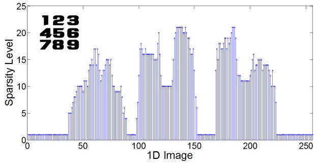
In image restoration, the representation matrix is generally the DCT or wavelet transform. However, the conventional DCT-based or wavelet-based image representation cannot always be the sparsest one when dealing with different types of images. These pre-constructed dictionaries are restricted to images of a certain type, and cannot be used for a new family of images of interest. In addition, the proposed compressive imaging system is a line-scan camera, and a 2D image can be obtained by reconstructing every line-scan image with a certain number of compressive measurements. If the DCT is used as the representation matrix, the sparsity distribution of these line-scan images may fluctuate dramatically. To illustrate this problem, a simulation has been performed. The inset in Fig. 1 shows a 256 × 256 image. Every row of this image is sparsely represented in the DCT domain and the DCT coefficients more than one-tenth of the maximum are considered as the nonzero elements of the sparse vector. Figure 1 shows the sparsity levels of 256 DCT-coded images, and a dramatic fluctuation is clearly presented. On this account, the PSNRs of the recovered line-scan images in the experiment may vary significantly with the same number of measurements, which would badly affect the total PSNR of the 2D image. To overcome these limitations, dictionary learning which aims to learn an over-complete dictionary from a set of training images is proposed [15]. The training database of image instances should be similar to those anticipated in the application. For example, the samples to be imaged are biological cells, so the training set should cover as many cell types as possible. Moreover, the number of image patches taken from the training set should be large enough for feature extraction. The dictionary learning process is discussed in detail as follows. An matrix composed of P training square patches of length N is used to train an over-complete dictionary of size , with and . A new algorithm named K-SVD is proposed to solve the following problem at a given sparsity level S.
| (4) |
where , and is the sparse representation of the ith patch in terms of the columns of the dictionary . The K-SVD algorithm initializes an arbitrary dictionary and progressively improves it to optimize the Eq. (4). The specific iteration procedure consists of two basic steps: sparse-coding the signals in given the current estimated dictionary and updating the dictionary atoms given the sparse representation in .
Fig. 1.

The sparsity levels of 256 DCT-coded images. Inset: the tested 2D image.
As the dictionary learning approach presets a sparsity constraint and then designs an over-complete dictionary with this constraint, the fluctuation on the sparsity level will be smaller than that of DCT-coded images, which guarantees a more uniform recovery accuracy. Therefore, the learned dictionary is a more appropriate basis than the DCT, and with the same number of measurements, the dictionary learning approach can enable higher recovery accuracy.
3. Experimental setup
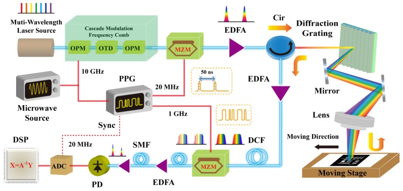
The experimental architecture of the proposed fast line-scan single-pixel camera is shown in Fig. 2. The optical source is a 40-wavelength laser array and the spacing between adjacent wavelengths is 0.8 nm. The multi-wavelength laser is used to generate 7 spectral lines spanning from 1550.12 nm to 1559.79 nm with a wavelength spacing of 1.6 nm as shown in Fig. 3(a). Then two optical phase modulators (OPMs) both driven by a 10-GHz microwave signal and an optical time delay (OTD) are employed to produce an optical frequency comb with a bandwidth of 11 nm as shown in Fig. 3(b). By choosing the proper wavelength channels, we can make the bandwidth of the frequency comb tunable. Thus the FOV of the proposed compressive imaging system can be widened if we increase the bandwidth. After the cascade modulation, a square-wave signal with a 20-MHz repetition rate and a 1/50 duty cycle provided by a programmable pulse pattern generator (PPG) is used to modulate the optical frequency comb via a Mach-Zehnder modulator (MZM) to generate an optical pulse train with an average power of 1.5 dBm. Then a high-power Erbium-doped fiber amplifier (EDFA) is used to amplify the signal power to 19 dBm. After amplification, the optical pulses enter the imaging system through a circulator.
Fig. 2.

Experimental setup of the proposed compressive imaging system. PPG: pulse pattern generator, OPM: optical phase modulator, OTD: optical time delay, MZM: Mach-Zehnder modulator, EDFA: Erbium-doped fiber amplifier, Cir: circulator, DCF: dispersion compensating fiber, SMF: single mode fiber, PD: photodetector, ADC: analog-to-digital converter, DSP: digital signal processor.
Fig. 3.

The optical spectra (a) before the cascade modulation and (b) after the cascade modulation.
The imaging system is composed of a diffraction grating, an objective lens and a target board (1951 USAF resolution test chart) which is controlled by a stepper motor. The diffraction grating is used to convert the spectrum of an optical pulse into a one-dimensional (1D) rainbow beam, achieving space-to-wavelength mapping. The spatially dispersed pulses are focused with an objective lens and then illuminate a moving target board. The average optical power at the object is about 7 dBm. When the optical pulses reflect off the target board, the spatial information of this board is encoded into the spectrum of the consecutive pulses. A two-dimensional (2D) image can be obtained by moving the target board in the direction normal to the line-scan direction. After the spectrally-encoded beams re-enter the diffraction grating, they are recombined. The circulator then directs the optical pulses into an EDFA whose output power is about 10 dBm. A section of dispersion compensating fiber (DCF) () with a linear group delay response is located after the amplifier to perform wavelength-to-time mapping. Another MZM driven by a 1-GHz microwave signal is used to spectrally encode the optical pulses with different pseudo-random binary sequence (PRBS) patterns. After random modulation, the optical power of the pulses is decreased to 1.8 dBm. To compress the optical pulses temporally, two sections of 80-km single mode fiber (SMF) () are used. Another two EDFAs are needed to compensate for the power loss as shown in Fig. 2. After going through the second section of SMF, the compressed optical pulses with an average power of about −7 dBm are detected by a 1-GHz photodetector and then sampled by an analog-to-digital converter (ADC) synchronized with a 20-MHz clock provided by the PPG. When M serial measurements are accomplished, an observation vector can be obtained, where represents the target image and refers to the m-th PRBS pattern. Let denotes the laser pulse repetition rate. The frame rate of the proposed compressive imaging system is . Thus higher frame rates can be achieved by increasing the repetition rate of the square-wave signal.
4. Experimental results
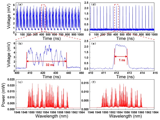
Figure 4 shows the temporal waveforms and the spectrum of optical pulses before random modulation (left) and after compression (right). A periodic sequence of spectrally-encoded optical pulses is shown in Fig. 4(a) and the temporal waveform of a single pulse is described in Fig. 4(b). It can be observed that the pulse duration is stretched to about 32 ns after dispersion and the pulse profile carries the spatial information of the target board. Figure 4(c) gives the optical spectrum of a dispersed pulse whose envelope is consistent with the pulse temporal profile. After going through a section of SMF, the stretched optical pulses are temporally compressed to nearly 1 ns as shown in Fig. 4(d) and 4(e). The optical spectrum of the compressed pulse is depicted in Fig. 4(f), showing no change in shape.
Fig. 4.
The temporal waveforms and the spectrum of optical pulses before random modulation (left) and after compression (right). (a) A 20-MHz optical pulse train whose spectrum is encoded with a spatial image (b) The temporal waveform of an optical pulse after dispersion. (c) The optical spectrum of one dispersed pulse. (d) The optical pulses after compression. (e) The temporal profile of one compressed pulse. (f) The optical spectrum of a pulse after compression.
Image reconstruction is firstly performed with the DCT-based algorithm and the corresponding results with different number of compressive measurements are shown in Fig. 5. In the experiment, the width of a scan line is about 5 mm and the step distance of the stepper motor is set at 10 μm. Each line-scan image can be reconstructed with a certain number of measurements. With the stepper motor moving in the direction normal to the line-scan direction (about 200 steps), a 2D image of size can be obtained. The horizontal pixel resolution of this 2D image is proportional to the ratio between the bandwidth of the optical frequency comb and the spatial resolution of the imaging system. In the experiment, the fiber dispersion (2.736 ns/nm) determines that the spatial resolution of the imaging system is governed by the grating dispersion [17]. According to the experimental parameters, the horizontal pixel resolution of the 2D image is approximately 250. In addition, the maximum number of horizontal pixels for a line-scan image is expressed as follows:
| (5) |
where is the total fiber dispersion, is the total multi-wavelength source bandwidth and is the pattern rate. In the experiment, to reduce the bitrate requirements of the PPG, a 1-ns PRBS bit is considered as six 167-ps PRBS bits so that the equivalent bitrate of the PRBS signal is increased by six times, resulting in a line-scan image composed of 250 pixels. Figure 5(a)-5(d) gives a part of the recovered images with a compression ratio of 32%, 40%, 60%, 80%, respectively. It is obvious that the recovery accuracy is proportional to the number of compressive measurements. However, the imaging speed of the proposed system will slow down with the number of measurements increasing. A trade-off between the frame rate and the recovery accuracy should be taken into consideration. In the experiment, the repetition rate of the optical pulses is 20 MHz and 100 measurements are used for image reconstruction so that a single-pixel camera with a frame rate of 200 kframes/s is achieved.
Fig. 5.

Image reconstruction with different number of compressive measurements. (a) 80 measurements. (b) 100 measurements. (c) 150 measurements. (d) 200 measurements.
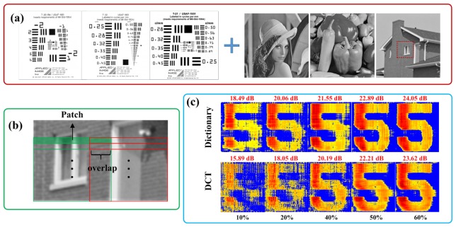
A further increase in imaging speed can be achieved by employing the dictionary learning approach. In the experiment, 10000 image patches are extracted from an arbitrary set of natural images shown in Fig. 6(a). Different types of USAF-1951 resolution targets (including USAF-1951 Standard Resolution Target (T-20), Low Contrast USAF-1951 Resolution Target (T-20-LC), USAF-1951 Direct Read Resolution Target (T-21) and USAF-1951 Linear Direct Read Resolution Target (T-22)) are used as the main training images. As the features extracted from patches in these training samples are relatively simple, to get more features, some complicated images are also incorporated into the training set. In the experiment, the bandwidth of the optical frequency comb is changed to 8 nm, so the number of the resolved pixels for a line-scan image is about 200. Correspondingly, the patch size is set at as shown in Fig. 6(b). The overlap size between adjacent image patches is and the sparsity level of the representation over the learned dictionary for an image patch is set at 10. With this sparsity constraint, an over-complete dictionary of size for sparse coding can be learned with the K-SVD algorithm.
Fig. 6.
Image reconstruction with the over-complete dictionary and the DCT basis at different compression ratios. (a) Sample images used for training the dictionary. (b) The patches taken from the tested images. (c) Image reconstruction with the over-complete dictionary and the DCT basis at different compression ratios (10%, 20%, 40%, 50%, 60%).
To validate the effectiveness of the learned dictionary, a performance comparison of the dictionary learning algorithm and the DCT-based algorithm is conducted. Figure 6(c) shows the recovery results using a learned dictionary and a DCT basis at different compression ratios. In the experiment, the number of the resolved pixels for a line-scan image is about 200 and 20, 40, 80, 100 and 120 compressive measurements are tested to recover images, respectively. The compression ratio and the PSNR of each recovered image are both indicated in Fig. 6(c). By increasing the number of measurements, the accuracy of the recovered image will be improved, and vice versa. The results in Fig. 6(c) illustrate that better recovery performance could be achieved by using the dictionary learning algorithm than the DCT-based algorithm at the same compression ratio and more obvious superiority can be observed at lower compression ratios. With the dictionary learning algorithm, fewer measurements will be needed which contributes to improving the frame rate of the proposed line-scan single-pixel camera. In Fig. 6(c), it can be also observed that the recovered image via dictionary learning at a compression ratio of 10% can be well recognized while at the same compression ratio the DCT-based image recovery is not satisfying. According to this result, a line-scan single-pixel camera with a 1-MHz frame rate can be achieved by employing the dictionary learning approach.
5. Conclusion
A fast time-lens-based line-scan single-pixel camera with multi-wavelength source is proposed in this paper, having achieved a frame rate of 1 MHz, which shows a significant improvement in imaging speed over conventional single-pixel cameras. By using a multi-wavelength laser instead of a MLL, the frame rate of the proposed compressive imaging system can be tuned conveniently. In addition, the learned dictionary from a set of training images for sparse representation has been demonstrated to be a more appropriate basis than the DCT and with the dictionary learning algorithm, the imaging speed can be further increased. This kind of high-speed single-pixel camera has the potential applications on biomedical imaging and surface inspection.
Acknowledgments
This work is supported by NSFC under Contracts 61120106001, 61322113, 61271134; by the young top-notch talent program sponsored by Ministry of Organization, China; by Tsinghua University Initiative Scientific Research Program; by State Environmental Protection Key Laboratory of Sources and Control of Air Pollution Complex under Contracts SCAPC201407 and by special fund of State Key Joint Laboratory of Environment Simulation and Pollution Control under Contracts 14K10ESPCT.
References and links
- 1.Donoho D. L., “Compressed sensing,” IEEE Trans. Inf. Theory 52(4), 1289–1306 (2006). 10.1109/TIT.2006.871582 [DOI] [Google Scholar]
- 2.Candes E. J., Romberg J., Tao T., “Robust uncertainty principles: exact signal reconstruction from highly incomplete frequency information,” IEEE Trans. Inf. Theory 52(2), 489–509 (2006). 10.1109/TIT.2005.862083 [DOI] [Google Scholar]
- 3.Candes E. J., “The restricted isometry property and its implications for compressed sensing,” C. R. Math. 346(9-10), 589–592 (2008). 10.1016/j.crma.2008.03.014 [DOI] [Google Scholar]
- 4.Candès E. J., Wakin M. B., “An introduction to compressive sampling,” IEEE Signal Process. Mag. 25(2), 21–30 (2008). 10.1109/MSP.2007.914731 [DOI] [Google Scholar]
- 5.Romberg J., “Imaging via compressive sampling [introduction to compressive sampling and recovery via convex programming],” IEEE Signal Process. Mag. 25(2), 14–20 (2008). 10.1109/MSP.2007.914729 [DOI] [Google Scholar]
- 6.Lustig M., Donoho D., Pauly J. M., “Sparse MRI: The application of compressed sensing for rapid MR imaging,” Magn. Reson. Med. 58(6), 1182–1195 (2007). 10.1002/mrm.21391 [DOI] [PubMed] [Google Scholar]
- 7.Duarte M., Davenport M., Takhar D., Laska J., Sun T., Kelly K., Baraniuk R., “Single-pixel imaging via compressive sampling,” IEEE Signal Process. Mag. 25(2), 83–91 (2008). 10.1109/MSP.2007.914730 [DOI] [Google Scholar]
- 8.Goda K., Tsia K. K., Jalali B., “Amplified dispersive Fourier-transform imaging for ultrafast displacement sensing and barcode reading,” Appl. Phys. Lett. 93(13), 131109 (2008). 10.1063/1.2992064 [DOI] [Google Scholar]
- 9.Goda K., Solli D. R., Tsia K. K., Jalali B., “Theory of amplified dispersive Fourier transformation,” Phys. Rev. A 80(4), 043821 (2009). 10.1103/PhysRevA.80.043821 [DOI] [Google Scholar]
- 10.Goda K., Tsia K. K., Jalali B., “Serial time-encoded amplified imaging for real-time observation of fast dynamic phenomena,” Nature 458(7242), 1145–1149 (2009). 10.1038/nature07980 [DOI] [PubMed] [Google Scholar]
- 11.Goda K., Jalali B., “Dispersive Fourier transformation for fast continuous single-shot measurements,” Nat. Photonics 7(2), 102–112 (2013). 10.1038/nphoton.2012.359 [DOI] [Google Scholar]
- 12.H. Chen, Z. Weng, Y. Liang, C. Lei, F. Xing, M. Chen, and S. Xie, “High speed single-pixel imaging via time domain compressive sampling,” in CLEO: 2014, OSA Technical Digest (Optical Society of America, 2014), paper JTh2A.132. [Google Scholar]
- 13.B. T. Bosworth and M. A. Foster, “High-speed flow imaging utilizing spectral-encoding of ultrafast pulses and compressed sensing,” in CLEO: 2014, OSA Technical Digest (Optical Society of America, 2014), paper ATh4P.3. [Google Scholar]
- 14.Bosworth B. T., Stroud J. R., Tran D. N., Tran T. D., Chin S., Foster M. A., “High-speed flow microscopy using compressed sensing with ultrafast laser pulses,” Opt. Express 23(8), 10521–10532 (2015). 10.1364/OE.23.010521 [DOI] [PubMed] [Google Scholar]
- 15.Aharon M., Elad M., Bruckstein A., “K-SVD: An Algorithm for Designing Overcomplete Dictionaries for Sparse Representation,” IEEE Trans. Signal Process. 54(11), 4311–4322 (2006). 10.1109/TSP.2006.881199 [DOI] [Google Scholar]
- 16.Duarte-Carvajalino J. M., Sapiro G., “Learning to sense sparse signals: simultaneous sensing matrix and sparsifying dictionary optimization,” IEEE Trans. Image Process. 18(7), 1395–1408 (2009). 10.1109/TIP.2009.2022459 [DOI] [PubMed] [Google Scholar]
- 17.Tsia K. K., Goda K., Capewell D., Jalali B., “Performance of serial time-encoded amplified microscope,” Opt. Express 18(10), 10016–10028 (2010). 10.1364/OE.18.010016 [DOI] [PubMed] [Google Scholar]


