Abstract
Modern hip prostheses feature a modular implant design with at least one tapered junction. This design can lead to several complications due to the introduction of additional interfaces, which are subjected to various loading conditions and micromotion. The main objective of current study is to develop a fretting corrosion apparatus, which is able characterize the mechanical and electrochemical behaviour of various existing metal alloy couples during fretting motion.
This study describes the design and the main considerations during the development of a novel fretting corrosion apparatus, as well as determination of the machine compliance and the initial testing results. Machine compliance considerations and frictional interactions of the couples are discussed in detail. For the preliminary tests, metal alloy pins, made of Ti6Al4V and wrought high-carbon CoCrMo were mechanically polished to a surface roughness of less than 20nm. 2 pins (Diameter = 11mm) of either Ti6Al4V or CoCrMo were loaded onto a Ti6Al4V alloy rod at a normal force of 200N. The interface types included: Ti6Al4V-Ti6Al4V-Ti6Al4V, Ti6Al4V-Ti6Al4V-CoCrMo, and CoCrMo-Ti6Al4V-CoCrMo. The Ti6Al4V rod articulated against the metal alloy pins in a sinusoidal fretting motion with a displacement amplitude of ±50μm. Bovine calf serum (30g/L of protein content) was selected as a lubricant and tested at 2 different pH levels (pH 3.0 and 7.6). In all cases, current and friction energy were monitored during the fretting process.
The results indicated distinct, material-specific current evolutions and friction energies. No significant differences were observed in electrochemical or mechanical behaviour in response to pH change. In general, Ti6Al4V-Ti6Al4V-Ti6Al4V couples displayed the earliest passivation and superior electrochemical behaviour compared to Ti6Al4V-Ti6Al4V-CoCrMo and CoCrMo-Ti6Al4V-CoCrMo under fretting conditions. In addition, fluctuations in current were observed in specific regions at all instances where Ti6Al4V was coupled with Ti6Al4V. These fluctuations were not observed in instances where Ti6Al4V was coupled with CoCrMo. These findings suggest transitions in the degradation mechanisms at the modular junction as a function of material couples/contacts. The findings may assist in improving the current hip modular junctions.
Keywords: fretting-corrosion, modular junction, Ti6Al4V alloys, CoCrMo
1. Introduction
Annually, 250,000 Total Hip Replacements (THR) are performed in the USA with an average lifespan of ten to fifteen years. As one of the most commonly performed surgical procedures, this number is estimated to increase to 500,000 by the year 2030 [1]. The complications related to THRs are typically early failure that occur within the first five years after implantation in 10% of patients [2]. Thus, there is a high demand to get high quality, economical and sustainable implants.
Several materials are currently being used for THR implants including ceramics, polymers and metals. Modularity of these implants is very common and it provides flexibility to the surgeon in the operating room [3]. In the human body, implants are exposed to adverse biochemical and mechanical interactions [4]. Their design is defined by the specific anatomy of the patient and consists of a tapered junction between femoral head and stem [5-8]. Modern hip implant prostheses feature at least one modular interface. Metal on Metal (MOM) tapered junctions are most commonly used due to their high mechanical properties; however, some of the current designs have shown fundamental difficulties in this complex environment and it could become a potential source for early failure [9]. Several previous studies on metal-on-metal implants reported corrosion and wear problems at the modular junctions [3, 10-11]. The use of Ti and CoCrMo metal in THR has raised concerns over the susceptibility of these metals to various forms of corrosion in association with mechanical stimuli such as, mechanically assisted corrosion (tribocorrosion), stress assisted corrosion, fretting-corrosion, and fretting crevice-corrosion under mechanical loading [12-17].
Generally, fretting-corrosion encompasses two contacting surfaces that are subjected to small displacements (10-200μm), depending on the area of contact. Several factors affect the fretting-corrosion process including mechanical, electrochemical and environment [18]. Previous studies have shown that the mechanical disruption of the passive oxide layer on the surface of the metallic biomaterial enhances the corrosion processes. Brown et al. [19-21] has demonstrated in their in vitro studies that the relative micro-motion between highly resistant metal alloys can lead to fretting-corrosion and release of metal ions. These may have deleterious effects to the patient [22]. Subsequently, in the fretting-corrosion phenomena, generated particles are transported through the contact area, leading to a severe chemical and mechanical active degradation zone. Any localized corrosion process (crevice or pitting corrosion) initiated during fretting may continue to accelerate even after the fretting is stopped [15, 23-24]. According to Swamynathan et al [24], the oxide repassivation inside the existing crevices with restricted fluid access results in the release of hydrogen ions and rise in acidity (HCl, H3PO4), which combined with cation release, causes a large deviation from normal physiological conditions [25].
When characterizing fretting-corrosion, the focus of the test method should be on understanding this complex interaction between the mechanical and electrochemical elements. As reported by Ingham et al. [26], the release of metal ions and particles from implant devices into the surrounding tissue and their transport to remote organs has been detrimental, highlighting possible adverse effects and symptoms. At present, the influence of key parameters such as surface potential, normal and tangential load, surface geometry, solution conditions, etc., on the fretting corrosion performance of metal-on-metal contacts is not completely understood. Furthermore, there have been limited attempts to precisely mimic the clinical conditions of the devices. Clinically, these devices are subjected to variable contact conditions, variable pH levels, and multiple taper interfaces (unpredictable contact area) are often present within the same device.
This investigation aims to develop a fretting corrosion apparatus, which is capable of characterizing the mechanical and electrochemical behaviour of the modular junctions with different metal alloy couples, under a complex contact geometry (flat-on-flat contact, similar the modular junctions), at different pH levels, and a multiple tapered implant system. The interface types included: Ti6Al4V-Ti6Al4V-Ti6Al4V, Ti6Al4V-Ti6Al4V-CoCrMo, and CoCrMo-Ti6Al4V-CoCrMo.
2. Experimental details
2.1 Development of fretting set-up
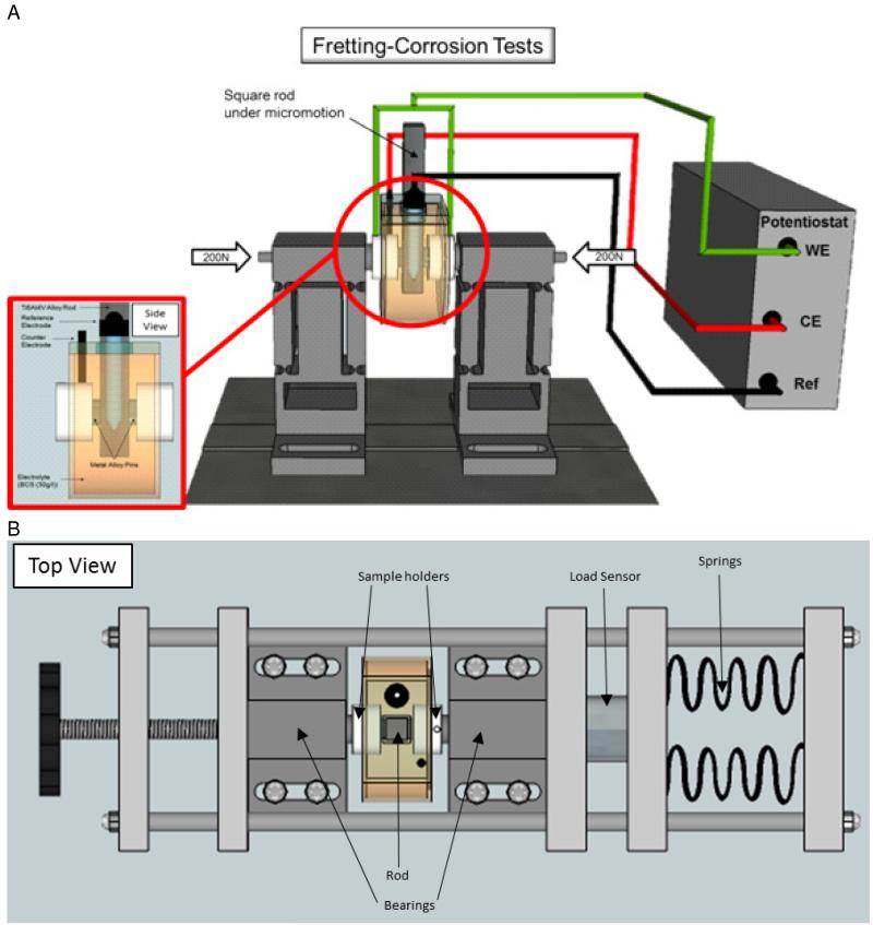
A fretting-corrosion apparatus was developed specifically for evaluation of hip implant modular junctions. The assembled view of the set-up and details of the tribcorrosion cell are provided in Figure 1. More details of the experimental set-up is explained below
-
(a)
Rod and pin holder: The contact configuration features 2 flat pins, which are loaded from both sides against a square rod. The tribological contact condition was flat-on-flat, (Pins-on-rod from both sides), to simulate the contact conditions at hip modular junctions. Although this design could potentially lead to problems with alignment and calculations of applied stress and contact area, the reproducible results and surface analysis suggest that optimal alignment was achieved and that any differences in contact area (resulting from asperities on the contacting surfaces) were not a major influence on the results.
The rod is then attached to a linear actuator, which imposes a linear micro motion onto the rod, against the pins. The pin holder, made of PEEK, is specifically designed to be used for electrochemical measurements as it is electrically non-conductive, and chemically inert. All components of the electrochemical cell should be non-conductive and chemically inert (with the exception of the test material, the counter, and the working electrode) in order to isolate the effects to the test material. The pin holder allows for electrical connection with the pin through wires emanating from the back of the pin. It is very important to isolate these wires from the electrolyte solution in order to measure the distinct properties of the pins. The wires should only be in electrical contact with the solution through the metallic pins (in series). This can be done by placing an O-ring around the pin interface to prevent any solution leakage into the pin holder. The aforementioned wire, connects the working electrode (pins) to the potentiostat, which provides the electrochemical measurements.
-
(b)
Fretting bearing: The pin holder is connected to a fretting hinge system which allows for lateral deflection but heavy resistance in the vertical direction (see the Figure 1). It is very important that the hinge system confers high rigidity in the tangential direction. Otherwise, it will be incapable of relaying the micro motion onto the articulating surfaces.
-
(c)
Load frame: A load frame, placed horizontally, allows for the application of the normal load through a spring-loaded compression system (Figure 1). The load frame contains a load cell (Loadstar Inc, CA), which measures the applied axial/normal force of the pins onto the square rod. The load frame is mounted onto the designated hinges of the bearings, which applies the specific axial load to the pin-rod interface. Changes in axial/normal load are constantly monitored in real-time with the data acquisition software supplied with the load sensor (ControlVUE, Loadstar, CA), and adjusted as necessary.
-
(d)
Vertical motion (fretting): The vertical motion is provided by any suitable actuator linear actuator. In this case, an Instron servohydraulic testing machine (Model 8871, Instron, Canton, Massachusetts) was used. Resultant load and displacement should be recorded by the data acquisition system. The top end of the rod is attached to the testing machine through a polymer (PEEK) ring. This allows for electrical insulation of the rod from the rest of the Instron Machine.
-
(e)
Fretting-corrosion cell: The corrosion cell is made of polysulfone, which is suitable for sterilizatiomn after the test if necessary (Figure 1). The cell is mounted onto the pin holders from both sides and filled with the electrolyte solution (60-70 ml). The corrosion cell is double-walled and designed to allow circulation of externally heated fluid through the second wall in order to heat the internal fluid. This ensures that the temperature of the internal fluid will be maintained at the required temperature (37°C) without the need for circulating the internal fluid or incorporating an internal heating mechanism. It is preferential to maintain the temperature of the internal electrolyte in this manner since any direct placement of a heating component into the electrochemical cell can interfere with the measurements due to the electromagnetic noise it can generate and the conductive components it introduces.
Figure 1.
(a) Fretting corrosion test chamber with a square rod undergoing micro motion against two, axially loaded, metallic pins. Electrode configuration consists of metallic pins coupled with the rod as the working electrode (WE), a graphite rod as the counter electrode (CE), and a saturated calomel electrode as the reference electrode. (b) Top view of the complete setup, including the load frame, which applies load axially onto the bearings. The bearings transmit the load through the sample holders, to the pins, onto the rod. The applied load is measured by a load sensor.
2.2 Sample Preparation
CoCrMo alloy and Ti6Al4V alloy were selected for the current investigation due to their frequent use in hip implant systems. The chemical compositions of the alloys are shown in the Table 1. In all tests, two cylindrical pins of either CoCrMo alloy or Ti6Al4V alloy (12mm diameter and 7mm thickness) articulated against a Ti6Al4V rod in flat-on-flat contact at an oscillatory frequency of 1Hz, with a nominal contact pressure of 1.73MPa. It is important to note that the actual contact pressure could not be determined due to the flat-on-flat contact used in these tests. Each testing condition was performed three times (N=3) to ensure repeatability. Prior to testing, all rods and pins were wet-ground using a series of silicone carbide grinding papers (up to #800). Following the wet-grinding procedure, the CoCrMo pins were brought to a mirror finish (Ra<25nm) with 6μm Polycrystaline Diamond Suspension (Beuhler, Lake Bluff, IL, USA) followed by 1μm polycrystaline diamond suspension (Beuhler, Lake Bluff, IL, USA). The Ti6Al4V pins were brought to a mirror finish (Ra<25nm) with 9um diamond paste (Beuhler, Lake Bluff, IL, USA) and MetaDi fluid (Beuhler, Lake Bluff, IL, USA), followed by polishing with colloidal silica suspension (Beuhler, Lake Bluff, IL, USA). The Ti6Al4V rods did not undergo any further polishing procedure beyond the wet-grinding. Before testing, all samples were ultrasonically cleaned with 70% isopropanol for 10 min, rinsed with deionized water and dried with nitrogen gas.
Table 1.
Chemical composition (in wt %) of the metal alloys used in the study.
| Composition (in wt%) | ||||||||
|---|---|---|---|---|---|---|---|---|
| Ti Alloy | Ti | Al | V | C | Fe | O2 | N2 | H2 |
| 89.62 | 6.1 | 4.0 | 0.004 | 0.16 | 0.106 | 0.008 | 0.0022 | |
|
| ||||||||
| CoCrMo Alloy | C | Co | Cr | Mo | Si | Mn | Al | |
| 0.241 | 64.60 | 27.63 | 6.04 | 0.66 | 0.70 | 0.02 | ||
2.3 Machine Compliance Evaluation
Before any testing could be done, the compliance of the test system had to be determined in order to know the deviation between the specified displacement (Xspec), input into the test system, and the actual real displacement (Xreal) between the articulating surfaces. In this case, the test system has two components, a linear actuator, and a tribocorrosion cell attachment. The real displacement (Xreal) at the pin-rod interface depends on the compliance of the linear actuator, the tribocorrosion cell attachment (Xcell), and elastic behaviour (Xelastic) of the Ti rod and CoCrMo pins and PEEK pin holder.
This shows that Xreal could be largely offset from Xspec, which is dependent on the rigidity of the set-up components, particularly at high axial load. In order to identify the relationship between the input and output parameters, the following machine compliance study was conducted.
-
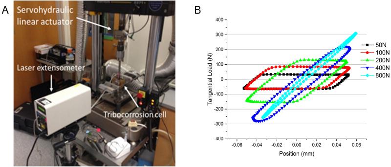
(a)Method: For these experiments, the machine compliance has been studied by conducting a series of experiments under displacement control, at a fixed displacement (Xspec: ± 50 um). An increasing amount of axial load (50, 100, 200, 400, 800N) was applied, until the sliding/fretting distance reached a value of approximately zero. Three metal couple combinations were tested (i) CoCrMo-Ti6Al4V-CoCrMo (Co-Ti-Co) (ii) Ti6Al4V-Ti6Al4V-CoCrMo (Ti-Ti-Co) (iii) Ti6Al4V-Ti6Al4V-Ti6Al4V (Ti-Ti-Ti). The experimental set-up is presented in Figure 2(a). The input parameters consisted of the axial load (AL) and specified displacement (Xspec). The measured output parameters consisted of the tangential load (TL) and real displacement (Xreal). The corresponding tangential load was recorded from the hysteresis loop recordings from the servohydraulic linear actuator. Similarly, the real displacement (Xreal) was determined from the hysteresis loop behaviour and verified with values from the laser extensometer. Then, the relationship between specified displacement (Xspec) and real displacement (Xreal), was expressed as percentage variation of displacement (%X)
-
(b)
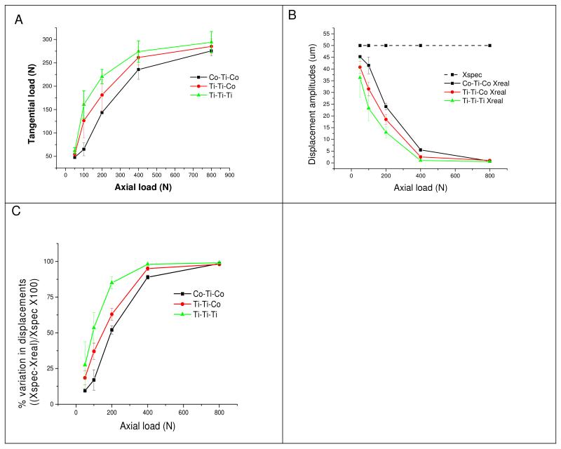
Results: A series of hysteresis loops were plotted as a function of axial load for each of the three metal combinations. Representative curves (Co-Ti-Co couple) are presented in Figure 2(b). Figure 3(a) and Table 2 show the relationship between applied axial load and the response of the tangential load. The compliance of the system can be estimated from these relationships of axial/normal load (input variables).
Figure 2.
The experimental set-up for the compliance study and (b) the effect of axial load on the hysteresis behaviour for a Co-Ti-Co couple. Note that the sliding/fretting distance reached a value of approximately zero in all couples at 800N applied load.
Figure 3.
The data from the mechnice compliance study including: (a) the relationship between tangential load and normal load from the experimental set-up for each coupe type, (b) the specified displacement (Xspec) and the resultant real displacement (Xreal) a function of axial load for each couple type, and (c) the percentage variation of displacement amplitudes for each couple type.
Table 2.
Data output from the machine compliance study in displacement control. Standard deviations are listed in the parentheses (where applicable).
| Normal Load(N) |
Tangential load(N) |
Xspec (um) |
Xreal (um) | % variation in displacement |
|
|---|---|---|---|---|---|
| Co-Ti-Co | 50 | 47.6 (1.8) | 50.0 | 45.3 (0.4) | 9.5 (0.7) |
| 100 | 65.1 (14.1) | 50.0 | 41.5 (3.6) | 17 (7.1) | |
| 200 | 143.6 (1.2) | 50.0 | 24 (1.4) | 52 (2.8) | |
| 400 | 235.8 (21.0) | 50.0 | 5.5 (0.7) | 89 (1.4) | |
| 800 | 275.7 (10.9) | 50.0 | 0.75 (0.4) | 98.5 (0.7) | |
|
| |||||
| Ti-Ti-Co | 50 | 54.3 (6.1) | 50.0 | 40.75 (2.5) | 18.5 (4.9) |
| 100 | 126.3 (36.5) | 50.0 | 31.5 (2.9) | 37 (5.7) | |
| 200 | 181.1 (32.8) | 50.0 | 18.5 (2.1) | 63 (4.2) | |
| 400 | 261.6 (15.7) | 50.0 | 2.5 (0.7) | 95 (1.4) | |
| 800 | 285.1 (16.3) | 50.0 | 1.0 (0.0) | 98 (0.0) | |
|
| |||||
| Ti-Ti-Ti | 50 | 61.7 (6.8) | 50.0 | 36.25 (8.2) | 27.5 (16.3) |
| 100 | 160.6 (29.3) | 50.0 | 23.25 (5.3) | 53.5 (10.6) | |
| 200 | 220.5 (15.5) | 50.0 | 13.0 (2.3) | 85 (4.2) | |
| 400 | 274.2 (23.0) | 50.0 | 1.0 (0.0) | 98 (0.0) | |
| 800 | 294.2 (22.7) | 50.0 | 0.5 (0.0) | 99 (0.0) | |
Figure 3(b) shows the relationship between specified displacement (Xspec) and real displacement (Xreal) as a function of axial load. Figure 3(c) shows the percent variation between the specified displacement and real displacement as a function of applied axial load. The values have been estimated according to the formula shown above. In these experiments, the sliding/fretting distance reached a value of approximately zero in all couples at 800N applied load (Figure 3(b)). This behaviour can also be seen in the behaviour of the hysteresis loops (Figure 2(b)). The load used in the original experiments was 200N, which showed a variation of 52% for the Co-Ti-Co couple, 63% for the Ti-Ti-Co couple, and 85% for the Ti-Ti-Ti couple (Figure 3(c) and Table 2). At loads higher than 200N, the variation is significantly higher.
2.4 Initial study: Fretting-corrosion of mixed metal- alloy couples under potentiodynamic mode
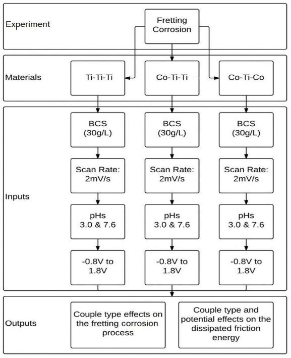
Fretting-corrosion tests were conducted under potentiodynamic conditions in order to evaluate the corrosion process in response to mechanical stimulation under a constantly changing potential, which is representative of the physiological environment. A potentiostat (G300, Gamry Inc., Warminster, PA) was used to induce a voltage range in all of the metal alloys in the coupled system, from −0.8V to 1.8V, at a scan rate of 2mV/sec and measure the change in current at the corresponding voltage. The experimental design was carried out with various combinations of metal couple types and 2 pH levels (Figure 4). In order to simulate a multiple modular junction interface the following couples were tested: Ti6Al4V-Ti6Al4V-Ti6Al4V (Ti-Ti-Ti), Ti6Al4V-Ti6Al4V-CoCrMo (Ti-Ti-Co), and CoCrMo-Ti6Al4V-CoCrMo (Co-Ti-Co).
Figure 4.
Experimental schematic of fretting corrosion tests under potentiodynamic mode.
The experimental set-up details were explained earlier in section 2.1. The test chamber contained two cylindrical pins of either CoCrMo alloys, Ti6Al4V alloy, or the combination of the two. The preparation protocol for the samples was explained earlier in section 2.2. The polished, flat ends were loaded against a Ti6Al4V rod at a normal force of 200N (Figure 1) within a test chamber. The Rod underwent a displacement of ±50μm. The electrolyte consisted of a diluted bovine calf serum (BCS) with a protein concentration of 30 g/L. In order to achieve this concentration, the BCS (initial protein concentration of 67 g/L (Newborn Calf Serum, Lot # 1231358, Gibco Inc., Grand Island, New York) was mixed with a solution of deionized water combined with NaCl (9 g/l), Tris (27 g/l), EDTA (200 mg/l), and enough HCl to bring the solution to pH 7.6. This solution was then separated and used to create a pH 3.0 variant by adding lactic acid. The electrochemical component of the test chamber consisted of a three-electrode electrochemical cell, which utilized a saturated calomel electrode (SCE) as the reference electrode (RE), a metal sample as the working electrode (WE), and a graphite rod as the counter electrode (CE). Tangential load, and current evolution were monitored throughout the test.
3. Results
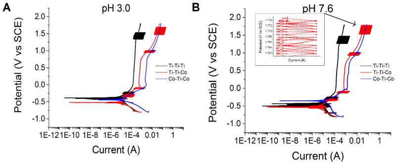
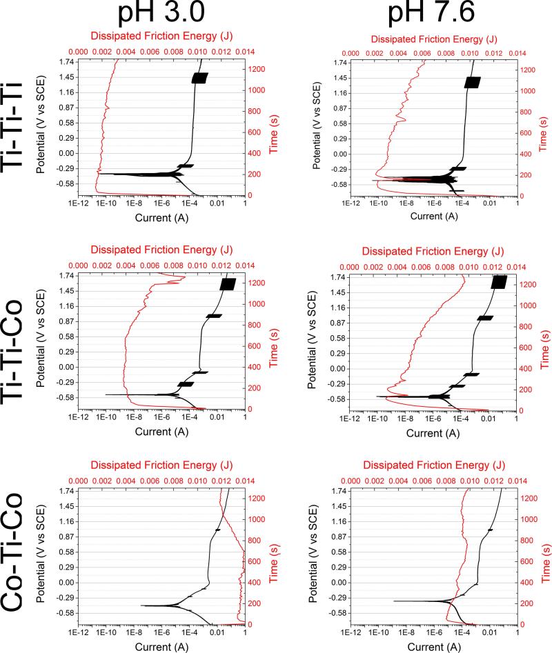
In general, all three combinations showed differences in both electrochemical and tribological behavior. Figure 5 shows the potentiodynamic curves of Ti-Ti-Ti, Ti-Ti-Co, and Co-Ti-Co couples at the two tested pH levels. Potentiodynamic tests indicated several interesting variations in the electrochemical nature under tribocorrosive (fretting-corrosion) exposure. Ti-Ti-Ti couples displayed the earliest passivation and the superior electrochemical behavior. The Ti-Ti-Co couple and the Co-Ti-Co couples exhibited very similar electrochemical behaviour under fretting conditions. Both couples displayed a trend towards pitting behavior at higher/anodic potentials; however, Ti-Ti-Co displayed fluctuations in current (indicative of the reciprocating fretting motion and its effect on the passivation) at certain potentials. Interestingly, Co-Ti-Co did not display any clear indication of the fluctuations in current. This suggests that a direct contact between Ti6Al4V and Ti6Al4V is the main cause of the high fluctuations in current. All tests and subsequent repeats displayed similar current fluctuations at the same potential regions. Although the Co-Ti-Ti and Co-Ti-Co displayed extremely similar behavior, it is evident that there was a shift towards a higher current density with increasing CoCrMo content in the system. The pH variation did not show significantly different behavior between pH 3.0 and pH 7.6.
Figure 5.
Potentiodynamic curves of Ti-Ti-Ti, Ti-Ti-Co, and Co-Ti-Co couples at (A) pH 3.0 and (B) pH 7.6. Fluctuations in current can be consistently seen at specific regions of the curve.
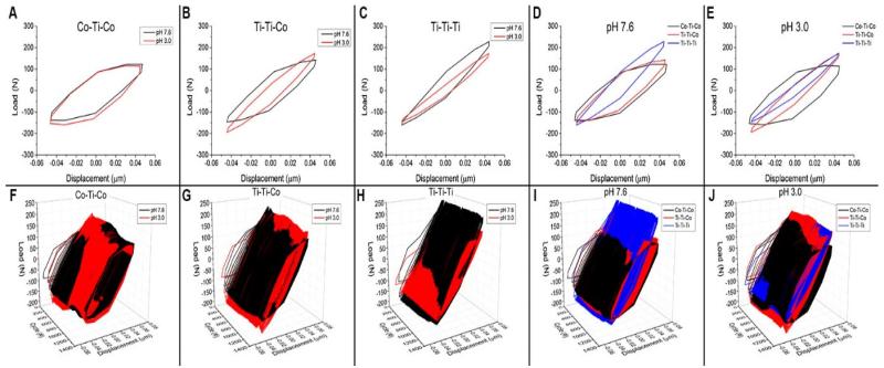
The fretting hysteresis loops (tangential load vs displacement) are presented in Figure 6. .Analysis revealed that all metal couples (Co-Ti-Co, Ti-Ti-Co, Ti-Ti-Ti) displayed different characteristics in tangential load vs. imposed displacement; however, no differences were seen between the 2 pH levels. Figure 6(A-E) shows the hysteresis behaviour (tangential load vs displacement) from a single cycle as a The evolution of hysteresis behaviour throughout the entire experiment, is shown in Figure 6(F-J). There was an inverse relationship between the amount of Ti alloy present in the interface and the cross-sectional area of the hysteresis loops.
Figure 6.
(A-E) Hysteresis loops (tangential load vs displacement) from a single cycle, shown as a function of couple type (Co-Ti-Co, Ti-Ti-Co, Ti-Ti-Ti) and pH level (3.0 and 7.6). (F-J) The evolution of hysteresis behavior throughout the experiment, shown as a function of couple type (Co-Ti-Co, Ti-Ti-Co, Ti-Ti-Ti) and pH level (3.0 and 7.6).
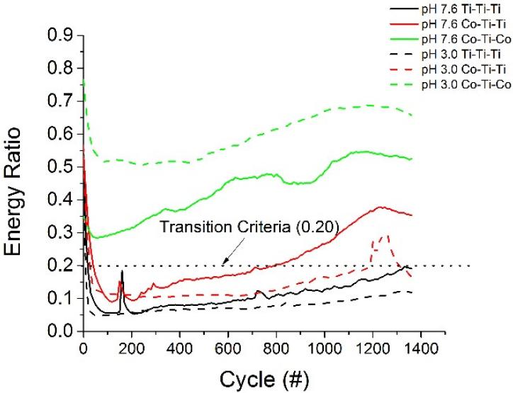
The energy ratio, as defined by Mindlin and Deresiewicz [27], is the coupled elastic-sliding response inducing a hysteresis tangential force vs. displacement loop evolution in ball on flat contacts [28] The area of the curve corresponds to the mechanical energy dissipated during the cycle. This relationship was used to characterize the fretting regime. Figure 7 shows the energy ratios of the various coupled alloy systems throughout the imposed fretting motion at the imposed displacement of ±50μm. Analysis of the energy ratios reveals that at the imposed fretting amplitude, only the Ti-Ti-Ti coupled system exhibited partial-slip behaviour (energy ratio < 0.20) throughout the entire test. The Ti-Ti-Co coupled system exhibited both partial slip and gross slip characteristics and the Co-Ti-Co coupled system exhibited only gross slip behaviour. It’s worth noting that the results depend on the frequency of recording (i.e. 10 Hz in these tests) and on the sensitivity of the tangential load sensor. These parameters have been considered as constant during experiments. Interestingly, the friction plateau was not constant and varied as the imposed potential of the system was changed.
Figure 7.
Energy ratio evolution throughout the fretting test.
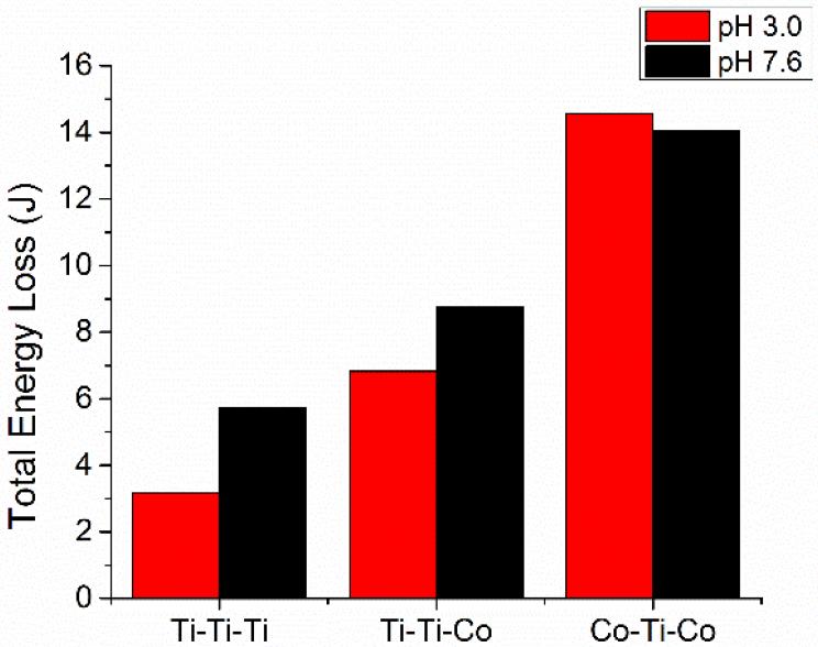
Figure 8 shows the total friction energy loss throughout the entire imposed fretting motion, calculated as the sums of all the individual areas of the hysteresis loops. The Ti-Ti-Ti couples displayed the lowest dissipated friction energy, followed by Ti-Ti-Co and Co-Ti-Co, respectively. In essence, a high dissipated friction energy was associated with the presence of CoCrMo. Figure 9 shows the evolution of dissipated friction energy as a function of potentiodynamic behaviour of the various metal couples and pH levels. There was a direct relationship of dissipated friction energy in response to increasing anodic potential/electrochemical conditions.
Figure 8.
Total friction energy loss throughout the entire imposed fretting motion.
Figure 9.
Evolution of dissipated friction energy as a function of potentiodynamic behavior of various metal couples (Ti-Ti-Ti, Ti-Ti-Co, and Co-Ti-Co) at normal and acidic pH levels (7.6 and 3.0).
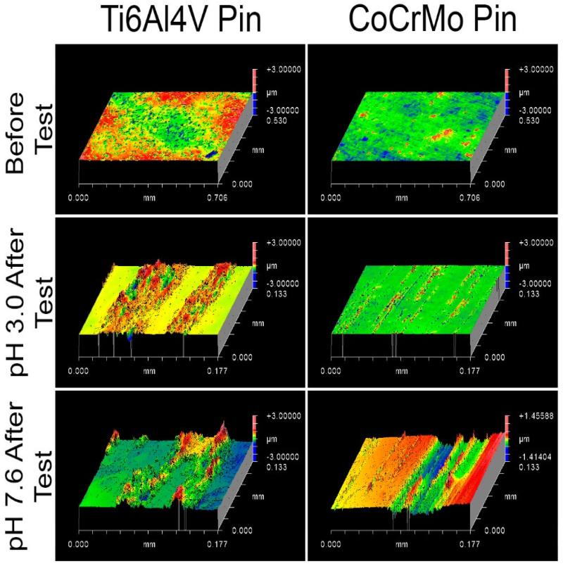
3D-profilomotric images of worn surfaces of the pins were taken using a white-light interferometer (Zygo New View, 6300), Figure 10. The images show that Ti alloy pins have deposits and/or plastic deformation on the surface. The CoCrMo pins show pitting and removal of material from the surface. Also, Ti alloy shows deposits with higher peaks at pH 7.6 compared to pH 3.0, and CoCrMo shows deeper valleys at pH 7.6 compared to pH 3.0.
Figure 10.
3D-profilometric images of worn surfaces of the pins (Ti and CoCrMo alloy) using a white-light interferometer (Zygo New View, 6300). The images show that Ti alloy pins have deposits and/or plastic deformation on the surface. The CoCrMo pins show pitting and removal of material from the surface).
4.0 Discussion
The results indicated distinct, material-specific, current evolution and friction energy, as a function of material couples/contacts. Some of observations are detailed below:
4.1 Behaviour of the metal couples under tribocorrosion-potentiodynamic mode
The corrosion potential, Ecorr, is the potential at which the test sample is at equilibrium between the anodic and cathodic reaction and hence, there is no flow of current. An important contributing factor to the corrosion of the metal alloy is the passivation behaviour of the metal. Where there is no passivation, and an anodic current increases in direct response to increasing potential. Passivation causes a deviation from linear response. Instead, a plateau in current is seen or sometimes a slight decrease in current is seen with increasing potential. Some point, the potential can be anodically increased to the extent that even the protectiveness of the passive film is negated and there is an increase in current flow in response to the increasing potential. The relative amount of current recorded is used to qualitatively assess the extent of corrosion occurring in the system. The evolved current which occurs at potentials higher than the corrosion potential leads to corrosion and pitting of the material. The potential where this behaviour is observed is called the pitting potential. Often the difference in voltage between the Ecorr and the breakdown potential are used to assess the corrosion behaviour of the material.
A relative comparison of Figure 9 reveals that Ti-Ti-Ti contacts show the earliest deviation from the linear response, indicating that the Ti-Ti-Ti couples formed a passive film before the other couples. Furthermore, the Ti-Ti-Ti contact did not show increases in current in response to higher anodic potentials, indicating that the passivation behaviour was stronger and the breakdown potential higher. Overall, the Ti-Ti-Ti couple displayed the best corrosion kinetics. The Ti-Ti-Co and the Co-Ti-Co couples displayed very similar corrosion kinetics and breakdown potential at approximately 0.75V (vs. SCE); however, there was an increase in current flow in response to increasing CoCrMo character indicating that CoCrMo induced higher amounts of corrosion and dissolution than Ti6Al4V under fretting conditions.
4.2 Evolution of dissipated friction energy as a function of electrochemical potential
It has been well documented that these load/displacement relationships are directly related to stress distributions, which alter the degradation mechanism. [28] Various regimes have been defined to describe these relationships. A partial slip regime corresponds to an elastic-sliding response with a contact point on the surface of the tested material surrounded by a pulsing sliding annular domain. Gross slip is defined by a full sliding period contact, which causes energy dissipating into the environment. Under partial slip regime, the hysteresis loop appears thin and elliptical as opposed to a gross-slip where the loops looks quadratic. The partial slip domain leads to a fretting-fatigue related failure of the material and gross slip leads to wear related failure. [28]
Figure 6 shows the hysteresis loop behaviour of the tangential load/displacement relationship of the three coupled systems and the relationship between the two tested pH levels. The cross-sectional area within these loops corresponds to the dissipated friction energy of the system. In general, there was no significant differences between pH. There was a very strong influence of the chosen material on the friction energy of the system (Figures 6, and Figure 8). Ti-Ti-Ti displayed the lowest dissipated friction energy, followed by Ti-Ti-Co and Co-Ti-Co respectively. The CoCrMo-Ti6Al4V contact increased the friction energy of the system. This effect was so strong that the contact mechanics changed and there was a shift in the degradation mechanism from partial slip to increasing levels of gross slip with increasing CoCrMo-Ti6Al4V contact (Figure 7). This suggests that Ti-Ti-Ti couples are more likely to fail due to fretting fatigue and Ti-Ti-Co and Co-Ti-Co couples are more likely to fail due to fretting corrosion.
4.3 Mechanistic transitions and Practical implications pertaining to metal couples used in modular junction
Previous studies have shown that there is a direct relationship between applied potential and the friction energy associated with the system.[29-30] In addition, previous studies have shown that there is a significant effect of tribocorrosive stimulation on the potentiodynamic behaviour of passive metals. [29-30] The important findings in this study are the current fluctuations which are consistently present at specific potentials in Ti6Al4V-Ti6Al4V interfaces (Figure 5). These fluctuations could be evidence of a repassivation potential region of Ti6Al4V, which are normally not seen in potentiodynamic curves of Ti6Al4V due to strong initial passivation behaviour.[31-33]
The fretting motion may provide enough passivation disruption to allow this repassivation region to become visible and fluctuation current magnitude indicate significantly high values. Ti alloys are known for their superior electrochemical properties; however, they have an inherent weakness in mechanical characteristics such as hardness compared to CoCrMo alloy. Hence, one would expect the CoCrMo couple to exhibit superior behaviour, but as the findings indicated, Ti-alloy could sideline its mechanical weakness through its superior electrochemical nature, under certain fretting condition. In contrast, higher fluctuations of current may increase the metal ion release, which could lead to weaker mechanical properties and increase the mechanical damage. Hence further studies (fretting-corrosion under postentiostatic and free-potential mode) are required to verify these findings.
Overall, the findings suggest that Ti-Ti-Ti couples display the most favourable electrochemical and tribological properties under certain fretting conditions. In general, several patterns of current variation and dissipated friction energy response were observed during the fretting process. Unlike previous studies, this study determined the pH variation (pH 3.0 and pH 7.6) did not induce a deviation in the electrochemical behavior. It is well known that the pH variation does impact passivation and potential change. The artificially controlled potential levels overcame the electrochemical effects of the solution to control the passivation.
It is worth noting that coefficients of friction and the compliance of the system may explain the results presented; however, these are specific effects that are dependent on the material properties. The aim of this work was to emphasize the universal effects of choosing various material couples and to postulate how these can materials can behave in clinical settings. For example, it is evident from the data that Ti6Al4V undergoes more elastic deformation and contributes much more to compliance of the system than CoCrMo. These are specific effects that can be directly attributed to the lower Young’s elastic modulus of the Ti6Al4V compared to the CoCrMo (113GPa vs 240GPa, respectively)[34] as well as the increased friction coefficient in Ti-Ti interfaces[24]. This study attempts to evaluate these effects in a much more broad perspective. In that respect, one can conclude that identical normal loads and displacements will have different effects in different couples, and therefore their failure mechanism can transition. In this case, the Co-Ti interfaces had a smaller compliance and more dissipated friction energy compared to Ti-Ti. This suggests that, Co-Ti couples would be more likely to fail by an abrasive wear mechanism and would therefore also experience more passivation layer disruption. In contrast, the Ti-Ti couples would undergo more elastic deformation and would have a higher compliance. Therefore, there would be less passivation disruption, less current, and the method of failure would more likely be a fatigue mechanism.
In general, the synergistic interactions of the fretting and corrosion processes have to be equally considered when selecting modular joint materials. The total degradation will be driven by the dominating mechanism, based on the nature of materials in contact and this could be influenced by the chemical nature of the surrounding environment. Hence, in modular junctions, material couple selection is a critical factor. It is important to mention that these findings are based on short duration fretting-corrosion tests. Long duration tests are necessary to verify these findings. The local changes of pH levels (even at interface) were not monitored and it can be different from the surrounding reported pH levels. Further studies will be performed by considering more clinically relevant factors, such as in a bioreactor setting, in order to solve the clinical concerns of the patients and clinicians. It is also worthwhile to consider a model which precisely represents the degradation process at modular junctions, by considering the mechanical, chemical and electrochemical variation.
4.4 Limitations of the Study
There are several limitations to this study. Firstly, in order to simulate a contact geometry, a flat-on-flat contact was used; however, with this geometry it is not possible to know the exact contact pressure. These tests were conducted with nominal contact pressure in mind. It is possible that at the start of the tests, only a few very small points were in contact which would lead to underestimation of the contact pressure, and exact contact area increased as the material was degraded, giving a lower contact pressure at the end of the test. Another issue is that the Ti-Ti-Ti system is the most deformable system due to the material properties of Titanium.[34] It is unclear whether this deformation is directly translatable into the clinical situation with a taper. In particular, the Ti pins might perform better because they see less fretting motion compared with CoCr (due to higher deflection). In fact, as shown by the compliance study, the Ti-Ti-Ti couples showed a reduction in relative displacement of approximately 85%, followed by Ti-Ti-Co (approximately 63%), and finally Co-Ti-Co couples showed a reduction in displacement of approximately 52% under identical testing conditions. Even though Ti-Ti compliance severely hindered the imposed motion amplitude compared to the Co-Ti couples, they demonstrate how certain motions and forces can severely alter the electrochemical and mechanical degradation mechanisms of materials, in this case, overcoming the mechanical weakness of Ti. Another limitation to this study was that the energy ratio used to determine the fretting regime, was never proven for flat-on-flat contact. It is possible that a different transition criteria exists in flat-on-flat contact; however, the principle of transferred energy is still valid, it is just a matter whether the value of 0.2 is valid. Additionally, in these tests, the normal load of 200 N has shown very distinct relationships in electrochemical and mechanical behavior; however, different normal loads may influence the energy ratio and produce different results. Finally, these tests were conducted at less than 1400 cycles, which are short duration tests. Under long duration stimulation, these materials may exhibit different results.
5.0 Conclusions
In this investigation, a fretting-corrosion apparatus was developed for the specific application of hip modular junctions and an initial study was conducted on the three different metal alloy couples, used for the hip prostheses. Machine compliance and frictional interactions of the metal alloy couples played a role in determining the tribocorrosion behaviour and mechanistic transitions. Based on the tested conditions, Ti-Ti-Ti couples displayed the most favourable electrochemical and tribological properties. However, higher fluctuations of current may increase the metal ion release and mechanical damage. Hence further studies (fretting-corrosion under postentiostatic and free-potential mode) are required to verify these findings. The resultant findings could assist in improving the current limitations of the hip modular junctions.
Research highlights.
Novel fretting-corrosion set-up has been developed for the hip modular junctions
Machine compliance study has been conducted
Three-commonly used metal alloy couples were studied
Machine compliance and frictional interactions played a role in the tribocorrosion process.
The findings could assist in improving the hip modular junctions
Acknowledgements
The authors would like to acknowledge the financial support from the NIH(National Institute of Health)R03AR064005,United States and NSF(National Science Foundation,CMMI #1160951). CoCrMo alloy samples were provided by ATI Alvac Inc. Fruitful discussion/suggestions were received from Dr.M.Laurent and Dr.R.Pourzal (Rush University Medical Center, Chicago, IL, USA)Prof. Alfons Fischer (University of Duisburg,Germany) and the members of the Institute of Biomaterials, Tribocorrosion and Nano-medicine(IBTN) (Chicago,IL,USA).
Footnotes
Publisher's Disclaimer: This is a PDF file of an unedited manuscript that has been accepted for publication. As a service to our customers we are providing this early version of the manuscript. The manuscript will undergo copyediting, typesetting, and review of the resulting proof before it is published in its final citable form. Please note that during the production process errors may be discovered which could affect the content, and all legal disclaimers that apply to the journal pertain.
References
- 1.Bozic KJ, et al. The Epidemiology of Revision Total Hip Arthroplasty in the United States. Journal of Bone and Joint Surgery. 2009;91(1):128–133. doi: 10.2106/JBJS.H.00155. [DOI] [PubMed] [Google Scholar]
- 2.Katz J, et al. Prevalence and risk factors for periprosthetic fracture in older recipients of total hip replacement: a cohort study. BMC Musculoskeletal Disorders. 2014;15(1):168. doi: 10.1186/1471-2474-15-168. [DOI] [PMC free article] [PubMed] [Google Scholar]
- 3.Kop AM, Swarts E. Corrosion of a Hip Stem With a Modular Neck Taper Junction: A Retrieval Study of 16 Cases. The Journal of Arthroplasty. 2009;24(7):1019–1023. doi: 10.1016/j.arth.2008.09.009. [DOI] [PubMed] [Google Scholar]
- 4.Bozic K, et al. Risk Factors for Early Revision After Primary Total Hip Arthroplasty in Medicare Patients. Clinical Orthopaedics and Related Research®. 2014;472(2):449–454. doi: 10.1007/s11999-013-3081-9. [DOI] [PMC free article] [PubMed] [Google Scholar]
- 5.Cooper HJ. The Local Effects of Metal Corrosion in Total Hip Arthroplasty. Orthopedic Clinics of North America. 2014;45(1):9–18. doi: 10.1016/j.ocl.2013.08.003. [DOI] [PubMed] [Google Scholar]
- 6.Molloy DO, et al. Fretting and corrosion in modular-neck total hip arthroplasty femoral stems. J Bone Joint Surg Am. 2014;96(6):488–93. doi: 10.2106/JBJS.L.01625. [DOI] [PubMed] [Google Scholar]
- 7.Davies JF, et al. Letter to the Editor: In Response to “Modular Taper Junction Corrosion and Failure: How to Approach a Recalled Total Hip Arthroplasty Implant”. The Journal of Arthroplasty. 29(2):449–450. doi: 10.1016/j.arth.2013.10.028. [DOI] [PubMed] [Google Scholar]
- 8.Srinivasan A, Jung E, Levine BR. Modularity of the Femoral Component in Total Hip Arthroplasty. Journal of the American Academy of Orthopaedic Surgeons. 2012;20(4):214–222. doi: 10.5435/JAAOS-20-04-214. [DOI] [PubMed] [Google Scholar]
- 9.Mathew MT, et al. Significance of Tribocorrosion in Biomedical Applications: Overview and Current Status. Advances in Tribology. 2009;2009 [Google Scholar]
- 10.Brown SA, et al. Fretting corrosion accelerates crevice corrosion of modular hip tapers. Journal of Applied Biomaterials. 1995;6:19–26. doi: 10.1002/jab.770060104. [DOI] [PubMed] [Google Scholar]
- 11.McKellop HA, et al. Interface corrosion of a modular head total hip prosthesis. The Journal of Arthroplasty. 1992;7(3):291–294. doi: 10.1016/0883-5403(92)90051-q. [DOI] [PubMed] [Google Scholar]
- 12.Baxmann M, et al. The influence of contact conditions and micromotions on the fretting behavior of modular titanium alloy taper connections. Medical Engineering & Physics. 2013;35(5):676–683. doi: 10.1016/j.medengphy.2012.07.013. [DOI] [PubMed] [Google Scholar]
- 13.Kumar S, et al. Evaluation of fretting corrosion behaviour of CP-Ti for orthopaedic implant applications. Tribology International. 2010;43(7):1245–1252. [Google Scholar]
- 14.Bryant M, et al. Fretting corrosion characteristics of polished collarless tapered stems in a simulated biological environment. Tribology International. 2013;65(0):105–112. [Google Scholar]
- 15.Hallab NJ, et al. Differences in the fretting corrosion of metal-metal and ceramic-metal modular junctions of total hip replacements. Journal of Orthopaedic Research. 2004;22:250–259. doi: 10.1016/S0736-0266(03)00186-4. [DOI] [PubMed] [Google Scholar]
- 16.Kim K, et al. Fretting corrosion damage of total hip prosthesis: Friction coefficient and damage rate constant approach. Tribology International. 2013;60(0):10–18. [Google Scholar]
- 17.Geringer J, et al. Electrochemical Impedance Spectroscopy: Insights for fretting corrosion experiments. Tribology International. 2013;68:67–76. [Google Scholar]
- 18.Basak AK, et al. Corrosion-wear behaviour of thermal sprayed nanostructured FeCu/WC-Co coatings. Wear. 2006;261(9):1042–1050. [Google Scholar]
- 19.Brown SA, Hughes PJ, M. K. In vitro studies of fretting corrosion of orthopaedic materials. J Orthop Res. 1988;6(4):572–9. doi: 10.1002/jor.1100060415. [DOI] [PubMed] [Google Scholar]
- 20.Brown SA, M. K. Fretting corrosion in saline and serum. J Biomed Mater Res. 1981;15(4):479–88. doi: 10.1002/jbm.820150404. [DOI] [PubMed] [Google Scholar]
- 21.Brown SA, M. K. In vivo and in vitro considerations of corrosion testing. Biomater Med Devices Artif Organs. 1981;9(1):57–63. doi: 10.3109/10731198109117601. [DOI] [PubMed] [Google Scholar]
- 22.Goldberg JR, Gilbert JL. In vitro corrosion testing of modular hip tapers. Journal of Biomedical Materials Research Part B: Applied Biomaterials. 2003;64B(2):78–93. doi: 10.1002/jbm.b.10526. [DOI] [PubMed] [Google Scholar]
- 23.Kraft CN, B. B, Diedrich O, Wimmer MA. Implications of orthopedic fretting corrosion particles on skeletal muscle microcirculation. Journal of Material Science: Materials in Medicine. 2001;12:1057–1062. doi: 10.1023/a:1012854325474. [DOI] [PubMed] [Google Scholar]
- 24.Swaminathan V, Gilbert JL. Fretting corrosion of CoCrMo and Ti6Al4V interfaces. Biomaterials. 2012;33(22):5487–5503. doi: 10.1016/j.biomaterials.2012.04.015. [DOI] [PubMed] [Google Scholar]
- 25.Rodrigues Danieli C., et al. In vivo severe corrosion and hydrogen embrittlement of retrieved modular body titanium alloy hip-implants. J Biomed Mater Res B Appl Biomater. 2010;88(1):206–219. doi: 10.1002/jbm.b.31171. [DOI] [PMC free article] [PubMed] [Google Scholar]
- 26.Ingham E, Fisher J. Biological reactions to wear debris in total joint replacement. Proceedings of the Institution of Mechanical Engineers, Part H: Journal of Engineering in Medicine. 2000;214(1):21–37. doi: 10.1243/0954411001535219. [DOI] [PubMed] [Google Scholar]
- 27.Mindlin RD, Deresiewicz H. Elastic spheres in contact under varying oblique forces. J. of Appl. Mech. 1953;20 [Google Scholar]
- 28.Fouvry S, Kapsa P, Vincent L. Quantification of fretting damage. Wear. 1996;200:186–205. [Google Scholar]
- 29.Chen J, et al. Effect of applied potential on the tribocorrosion behaviors of Monel K500 alloy in artificial seawater. Tribology International. 2015;81:1–8. [Google Scholar]
- 30.Mathew MT, et al. What is the role of lipopolysaccharide on the tribocorrosive behavior of titanium? J Mech Behav Biomed Mater. 2012;8:71–85. doi: 10.1016/j.jmbbm.2011.11.004. [DOI] [PubMed] [Google Scholar]
- 31.Abey S, et al. Electrochemical Behavior of Dental Implants (CpTi): Influence of pH of Artificial Saliva. The Journal of Oral Implantology. 2011 doi: 10.1563/AAID-JOI-D-11-00054. [DOI] [PubMed] [Google Scholar]
- 32.Barao VA, et al. The role of lipopolysaccharide on the electrochemical behavior of titanium. J Dent Res. 2011;90(5):613–8. doi: 10.1177/0022034510396880. [DOI] [PubMed] [Google Scholar]
- 33.Barão VAR, et al. Stability of cp-Ti and Ti-6Al-4V alloy for dental implants as a function of saliva pH - an electrochemical study. Clinical Oral Implants Research. 2012;23(9):1055–1062. doi: 10.1111/j.1600-0501.2011.02265.x. [DOI] [PubMed] [Google Scholar]
- 34.Royhman D, et al. An electrochemical investigation of TMJ implant metal alloys in an artificial joint fluid environment: The influence of pH variation. Journal of Cranio-Maxillofacial Surgery. doi: 10.1016/j.jcms.2014.01.029. [DOI] [PubMed] [Google Scholar]


