Abstract
We present a new fabrication method to produce arrays of highly responsive polymer-metal core-shell magnetic microactuators. The core-shell fabrication method decouples the elastic and magnetic structural components such that the actuator response can be optimized by adjusting the core-shell geometry. Our microstructures are 10 μm long, 550 nm in diameter, and electrochemically fabricated in particle track-etched membranes, comprising a poly(dimethylsiloxane) core with a 100 nm Ni shell surrounding the upper 3–8 μm. The structures can achieve deflections of nearly 90° with moderate magnetic fields and are capable of driving fluid flow in a fluid 550 times more viscous than water.
Keywords: actuators, core-shell, biomimetics, microelectromechanical systems
1. Introduction
Responsive micro- and nanostructures are critical to the future of many nanotechnologies due to their uses as sensors and actuators, providing means for interactions between a system and its environment. In particular, magnetically driven actuation is appealing because it has the potential to achieve large displacements without internal on-chip power sources or leads. To date, however, magnetic microactuators have been limited by an intrinsic tradeoff between the structures’ flexibility and the magnetic force which can be imparted. The balance between these two factors determines the actuators’ responsiveness. Current designs for such magnetic microactuators include chemically or magnetically linked paramagnetic beads [1–3], thin magnetic films deposited onto flexible substrates [4–7], and elastic polymers loaded with varying concentrations of magnetic particles [8–13]. In virtually all current methods, magnetic microactuators combine magnetic elements with flexible substrates in such a way that increasing the amount of magnetic material (or magnetic loading) increases the amount of force one can apply, but comes at the expense of a decrease in the flexibility of the actuating structure. In addition, each of the above types of structures is limited by at least one of the following: lack of tunability due to the use of particles which may be only commercially available, inability to generate structures of sub-micron sizes, and particle aggregation, which limits actuator size and leads to nonuniform response from structure to structure.
Here we present the fabrication of a new type of core-shell microactuator which partially decouples the flexibility of the structure from its magnetic properties. We accomplish this by producing an array of silicone polymer core-shell microrods in which only the top portion of each microrod is encased in a nickel shell. With this structure, the flexibility is solely determined by the choice of polymer and the length of the exposed polymer at the base of each rod, while the magnetic loading can be tuned by varying the length and thickness of the nickel shell. Thus, the magnetic and elastic responses can be optimized independently. We have demonstrated static deflections of these structures such that the tips of the rods contact the substrate floor, through 90° of bending with the application of modest magnetic fields. As an application of their responsiveness and force generation capability, we demonstrate flow driven by these structures in fluids up to 550 times more viscous than water.
The core-shell geometry of the structures presented here are the first to function as magnetically driven microactuators, but a number of core-shell rod-like structures have been previously demonstrated for other applications. These applications include magnetic antennae [14], sensors in electronic devices [15, 16], chemical sensors [17], and components in solar cells [18, 19]. Most of the focus has been on nanorods with a metal core surrounded by a metal or metal-oxide shell [15, 19–22]. When polymers are incorporated as either the core or the shell, they are typically rigid or semi-rigid conducting polymers such as polyaniline [14, 18] or polypyrrole [23]. Additionally, though they are not core-shell structures, polymer-metal hybrid nanotubes have been created for use as electromagnetic actuators [24] and drug delivery carriers [25]. By replacing the semi-rigid conducting polymers with silicone and utilizing a ferromagnetic metal, we have constructed a new, highly responsive actuator that can be fabricated and actuated at the micron scale.
Artificial cilia-like microactuators have been widely pursued for pumping and mixing applications in microfluidics. In recent years, a number of fabrication schemes for cilia-like actuators have been explored, and many actuation techniques have been employed. These techniques include the use of visible and UV light [26], electrostatics [27], SEM e-beams [28], a PZT microstage [29], and time varying magnetic fields [3, 9, 30, 31]. In earlier work, we utilized a single rotating permanent magnet with applied magnetic fields and field gradients on the order of 5000 Oe and 50 kOe/cm to actuate arrays of 25 μm tall, 700 nm diameter cilia fabricated with a ferrofluid-poly(dimethylsiloxane) (FFPDMS) composite material. We also used these structures to generate long-range directed flows at speeds of 8 μm/s in a low viscosity fluid [31].
For many microactuator applications, including fluid manipulation, the structures’ responsiveness is a key parameter for describing their utility and performance. In addition, responsiveness can be important in both a static and a dynamic context. Static responsiveness describes the steady-state maximum amplitude an actuator can achieve in response to an applied constant force. The amplitude of an actuator at an applied force and a given frequency is the dynamic responsiveness of the actuator, from which the static responsiveness could be determined by taking the low frequency limit. At micron scales, the dynamic responsiveness is typically limited by viscous interactions with the surrounding fluid and the small volume of the structure, which limits the driving force that can be applied. The latter limitation may also affect static responsiveness of actuators near the micron-scale. Many of the structures previously discussed, including our own earlier work, suffer from limited static and/or dynamic responsiveness, and so a primary motivation for our development of core-shell actuators has been to overcome these limitations. Mechanical modeling of microactuators as damped driven harmonic oscillators demonstrates that structures of similar dimensions and material properties to the structures presented herein are highly overdamped in aqueous fluids, and may be overdamped in air, depending on the structure’s mass (see supplementary data for additional discussion). This suggests the need for actuator designs that maximize the static force that can be generated without sacrificing flexibility.
2. Experimental
2.1 Materials
Polycarbonate track-etched (PCTE) membranes were commercially obtained from it4ip (www.it4ip.be) with a thickness of 10 μm and pore diameter of 200 nm. Nickel sulfate hexahydrate (NiSO4•6H2O), boric acid (H3BO3), sulfuric acid (H2SO4), dichloromethane (AC40692-0040), Triton-X (AAA16046AE), and Norland Optical Adhesive #81 (NC9586074) were obtained from Fisher Scientific. Poly(dimethysiloxane) (Dow Corning Sylgard 184), a widely used heat-curable silicone elastomer, was obtained from Ellsworth Adhesives. All materials were used as received.
2.2 Fabrication
We fabricate our core-shell actuators using hydrophobic polycarbonate track-etched (PCTE) membranes as a molding template, providing various options for rod length and diameter. Our microrods are 10 μm tall (as determined by membrane thickness) and typically 550 nm in diameter (as determined by pore size), though we have fabricated rods up to 25 μm tall and 2.5 μm in diameter. Pore diameters were increased from 200 nm to 550 nm by incubating membranes in 4M NaOH for approximately 30 minutes at 80°C. Within a membrane, enlarged pore diameters vary less than 5%, as confirmed by SEM imaging. After incubation, we rinsed the membranes in deionized water and dried them with a stream of N2; membranes were shown to be hydrophilic after etching with NaOH.
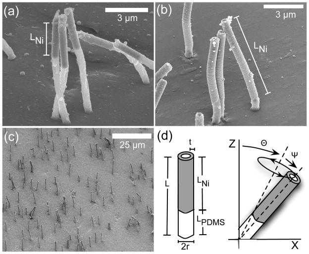
The core-shell structures consist of a PDMS core and Ni shell around the top portion, with a typical shell thickness of 100 nm and a shell length that can be varied from 2–9 μm along the upper portion of the rod. SEM images of core-shell rods are shown in figure 1; in (a–c), rods were critical-point dried with CO2 (Balzers Union CPD 020) to prevent collapse in air and coated with 10 nm Au/Pd prior to SEM imaging. The length and thickness of the Ni shell, and thus the magnetic permeability of the actuator, depends on the amount of Ni electrodeposited into the PCTE membrane, providing an easy route for tuning the magnetic response of these structures.
Figure 1.
(a–b) SEM images of core-shell rods taken on a 45° tilted stage show one method of controlling Ni shell size. The amount of electrodeposited Ni is identical, but the pore size in (a) is approximately 660 nm, and in (b) the pore size is 590 nm. Ni shell length is approximately 4 μm in (a) and 9 μm in (b). (c) SEM image of an array of core-shell rods. (d) Diagram describing rod parameters. The length of the rod L is the sum of the length of the Ni tube LNi and the length of the PDMS portion LPDMS. The radius of the rod is r, and the thickness of the Ni tube is defined as t. The tilt angle θ and half cone angle ψ of the rod beat are controlled by the direction and strength of the magnetic field. This asymmetrical beat shape produces a directional fluid flow [32].
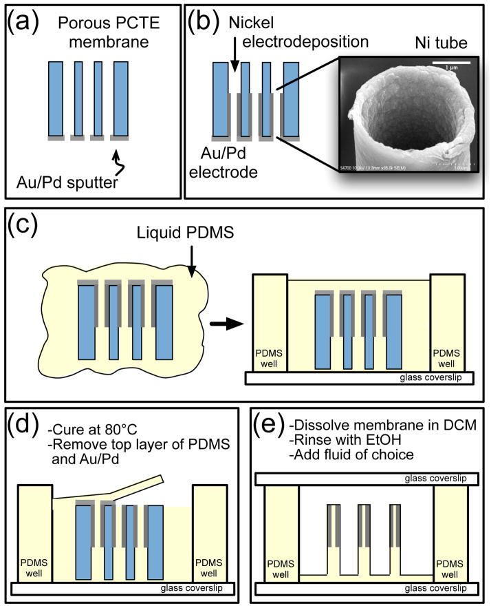
To provide a working electrode for the nickel deposition, we first sputtercoat 200 nm of Au/Pd onto one side of a PCTE membrane as shown in figure 2(a). This sputtered layer does not significantly occlude the pores as evidenced by SEM images taken after sputtering, and we suspect the lip of Au/Pd slightly overhanging the pore created by this sputtering influences the thickness of the Ni shell, providing one potential route for tuning the magnetic loading. We have fabricated rods with Ni tube thicknesses between 70 and 130 nm; variability is typically less than 15%. The membrane is then put into a three-electrode electrodeposition set-up with a Cu working electrode, Ag/AgCl reference electrode, and Pt auxiliary electrode. We place the Au/Pd sputtered side against the working electrode and electrodeposit Ni at a controlled voltage of −1 V, typically depositing 2.04 mC/mm2 to obtain Ni tubes (figure 2(b)). The Ni solution consists of nickel sulfate hexahydrate (NiSO4•6H2O, 60 g/L) and boric acid (H3BO3, 30 g/L) adjusted to pH 2.9 using sulfuric acid (H2SO4) [33]. For a given pore size, the length of the nickel tube may be tuned by adjusting the amount of Ni deposited, providing a second independent parameter for tuning magnetic loading. Figure 1 shows SEM images of two different pore sizes with an equal amount of Ni deposition; thus, the tubes produced are different lengths. Brightfield and SEM imaging of undamaged rods in multiple arrays has shown approximately 10–20% variability in Ni tube length. After deposition, the sample is rinsed with deionized water, dried with N2, and set on a 60°C hot plate for ten minutes until all fluid has evaporated. The sample is then immersed in uncured PDMS, which enters the pores and fills the Ni tubes (figure 2(c)).
Figure 2.
Cross-sectional description of core-shell rod fabrication procedure. (a–b) Au/Pd is sputtered onto the PCTE membrane and serves as the working electrode for Ni electrodeposition. The inset in (b) is an SEM image of a 3 μm Ni tube after deposition. (c) PCTE membrane is immersed in uncured PDMS and set inside a PDMS well structure. (d) The sample is thermally cured, and the upper layer of PDMS and Au/Pd is removed to expose the PCTE membrane. (e) The PCTE membrane is dissolved with DCM, and rods are rinsed with ethanol. The appropriate fluid is added, and the sample is sealed.
We place the PDMS-filled membrane inside a 200–300 μm tall PDMS well structure that has been previously plasma-bonded to a glass coverslip (figure 2(c)). This well structure is used as a fluid reservoir. The Au/Pd side of the membrane must be facing upward to ensure the Ni tube will enclose the upper portion of the core-shell microrod. The sample is degassed for approximately ten minutes, and the PDMS is cured in an oven at 80°C for at least one hour (figure 2(d)). After curing, the top layers of PDMS and Au/Pd are removed with tweezers to expose the polycarbonate, and the entire sample is immersed in dichloromethane to dissolve the PCTE membrane (figure 2(e)). The sample is rinsed with ethanol containing 0.05% Triton-X as a surfactant and can then be exchanged with aqueous solutions of the viscosity desired for experimentation. Occasionally during fluid exchange with a more viscous fluid, rods can be swept toward the ground or one another and experience ground or lateral collapse, resulting in a lower density array, which may cause a decrease in the resulting fluid velocity. The success of the adhesive forces which cause both ground and lateral collapse tends to be proportional to a rod’s aspect ratio; higher aspect ratios imply a higher likelihood of collapse. Additionally, the polymer PDMS is hydrophobic and thus has a lower surface energy when in contact with itself [34, 35]. With brightfield microscopy, we have qualitatively observed a greater likelihood of permanent collapse when a rod’s PDMS portion contacts the PDMS substrate or a neighboring rod’s PDMS tip.
All fluids are seeded with fluorescent microsphere tracer particles to visualize flow fields, and the top of the well is sealed with a glass coverslip and Norland Optical Adhesive to eliminate evaporation. All videos were captured using a Pulnix camera, model TM-6710CL (JAI, Inc.), and an EDT-PCI DV (Engineering Design Team) frame grabber card. The frame rate varied from 30–120 frames per second, and microsphere tracer particles were tracked utilizing CISMM Video Spot Tracker software (cismm.org/downloads). Microsphere velocities were computed with Matlab routines.
2.3 Characterization
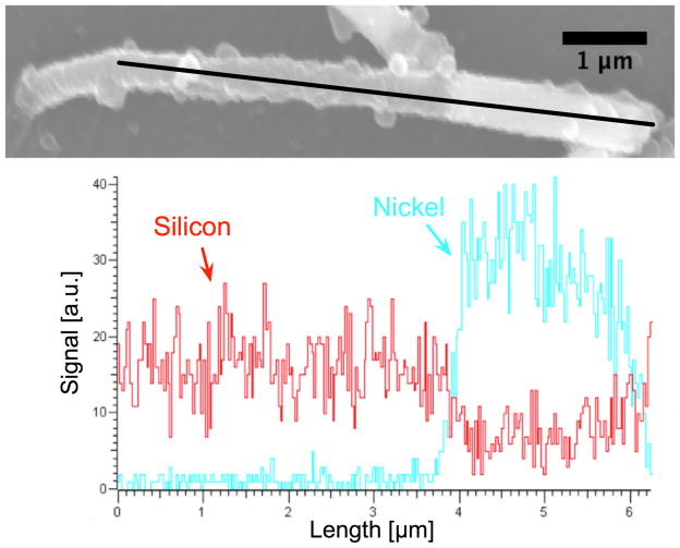
To confirm the presence of Ni, we performed an Energy Dispersive X-ray Spectroscopy composition analysis (INCA PentaFETx3, Oxford instruments) with the results shown in figure 3. The array of core-shell rods was air-dried to intentionally cause collapse for side-on imaging. To determine the composition along the length of the rod, we performed a scan from left to right, detecting a sharp change at the boundary of Ni and PDMS. The Ni signal increases dramatically, and a corresponding decrease in the silicon signal is observed as PDMS has a silicon-oxygen backbone.
Figure 3.
Energy Dispersive X-ray Spectroscopy line scan verifying the presence of Ni in a 10 μm long and 660 nm diameter core-shell rod with a Ni deposition of 2.04 mC/mm2. The tube length is approximately 4 μm, and tube thickness is 100 nm. At 4 μm into the scan, note the increase in Ni signal and decrease in Si signal. This change in material can also be seen in the SEM image; the Ni appears as a bright portion at the right end of the rod.
We utilized a Superconducting Quantum Interference Device (SQUID) magnetometer (Quantum Design Magnetic Property Measurement System) to characterize the magnetic properties of the microrods. Samples were fabricated as described, but in this case, left within the PCTE membrane; the final release step shown in figure 2(e) was not performed. The arrays were inserted into a straw holder such that the microrods were parallel or perpendicular to the applied magnetic field. All magnetization curves were run at 300 K. Initial runs over a large range of applied field determined that the nickel saturated at ±1400 Oe, and so future runs were performed over the range ±3000 Oe. The microrods’ saturation was the same whether the field was applied parallel or perpendicular, and the saturation magnetization was 397±13 emu/cm3. For normalization, the Ni content was known from measuring tube length (7.9±0.2 μm), tube thickness (73±6 nm), and rod diameter (441±13 nm) with the SEM, and estimating the approximate number of rods as 8.126 × 10⁴ using sample area and pore density. Literature values for the saturation magnetization of bulk Ni and Ni nanorods range from 480–535 emu/cm3 [36–38]. Coercivities for the perpendicular and parallel applied fields are 65 Oe and 125 Oe, respectively, which are consistent with values found in the literature for Ni nanotubes [39, 40], and are greater than bulk Ni (0.7 Oe) [41]. The ferromagnetic nature of the microrods was confirmed by the presence of hysteresis in the curves.
In addition, we checked for the presence of shape anisotropy which appears as a general shape change in the hysteresis curves. As shown in figure 4, data indicate there may be a subtle anisotropy: the sample with the rods’ axes aligned parallel to the applied field appears to approach saturation at lower applied field than rods which are aligned perpendicular to the applied field, as it takes more energy to rotate the moment of the individual domains away from the easy (long) axis of the rod. This shape anisotropy has been shown in previous magnetization studies of Ni nanotubes [42] and Ni nanorods with low template porosities. Larger porosities (>35%) have been shown to reduce the anisotropy due to the dipolar coupling between rods [43]. We use PCTE membranes with a porosity of 0.5%.
Figure 4.
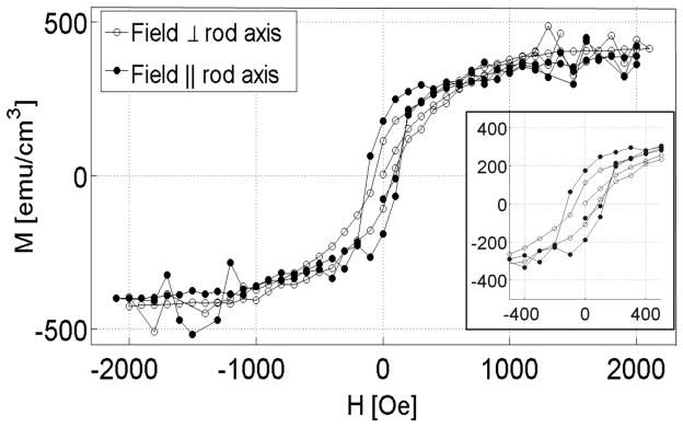
Magnetization curve for core-shell rods indicates a subtle shape anisotropy and confirms their ferromagnetic nature. The magnetic field was applied both perpendicular (○) and parallel (●) to the rod axis, and the signal is normalized by the volume of Ni present. The subtle shape anisotropy and coercivities (as shown in the inset) are consistent with the literature.
2.4 Actuation
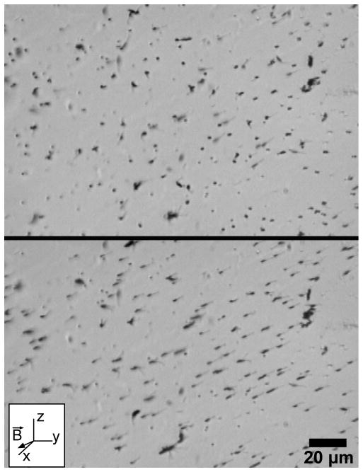
To magnetically actuate our microrod arrays, we use a rotating, rare-earth permanent magnet (K&J Magnetics, catalog no. BX084-N52) situated between 2–15 mm above the sample. This distance range corresponds to field strengths in the range 1200–50 Oe, respectively, as measured with a Hall probe. With the magnet centered over the sample, the field direction has a positive, constant z-component and an x-y component that is perpendicular to the rods’ initial upright positions. At the low end of this range, 50 Oe, we can achieve 20° bend angles with respect to the vertical. For comparison, this same field strength could also be generated by a current-carrying wire placed 20 μm from the array and running at 0.5 A. The actuation of an array with our rotating magnet setup is shown in figure 5 and in video S1. Also included is video S2, a sample of 1 μm diameter core-shell rods actuated by a rotating permanent magnet. Our previous studies have demonstrated that the bending mechanism in these types of structures is generally driven by the torque applied by the magnetic field, which tends to align the long axis of the rod with local magnetic field lines, and not by the force induced by the magnetic field gradient [8].
Figure 5.
Core-shell rods bend in the direction of the applied magnetic field. The top image shows a vertical array of 550 nm diameter rods with a Ni tube length LNi ≈ 3 μm. When we apply a magnetic field in the direction indicated in the diagram, the 10 μm rods bend in the direction of the field, as shown in the bottom image. For the video of this array actuating, see video S1.
3. Results and Discussion
Here we present results on the responsiveness of core-shell arrays and their actuation in viscous and viscoelastic fluids, and discuss the application of an energy minimization model that allows for optimizing the structures’ responsiveness. The application of a magnetic field of 300 Oe induces 90° bend angles of the nickel portion of the structure, as shown in figure 6(a) and 6(b) and video S3, demonstrating a high static responsiveness at moderate field strengths. This large bend angle is evident when, at the maximum bend angle, the tip of the rod actually comes into contact with the substrate and briefly sticks. Figure 6(a) is a minimum intensity projection of the first two seconds of a single rod from video S3; each dark stroke represents a single video frame of the motion of the rod. The video was taken at 30 frames per second. Figure 6(b) plots the average angular velocity of the rod as a function of time for a single rotation. The asterisks in both A and B indicate where the Ni tube is bending greater than 90° at the Ni-PDMS interface such that the rod’s tip comes into contact with the substrate. At this point the rod tip is attached and is restrained by this contact for roughly a tenth of a second. The large spike in angular velocity occurs just after the moment of constraint, as the rod releases from the substrate. Additionally, because the array is imaged in a reflectance brightfield mode, when the Ni tube is horizontal, it reflects light back to the camera. In figure 6(a), the two points at which this occurs are designated by arrows. This effect can be seen in video S3.
Figure 6.

With a low applied magnetic field (300 Oe), we can actuate the rods such that their Ni tubes contact the substrate. (a) Time lapse image of two seconds of a single rod’s rotational beat. Each dark stroke is a single video frame of the motion of the rod. The arrows indicate a brighter region where light reflects off the Ni tube. For the full movie, see video S3. (b) Average angular velocity as a function of time for the rod depicted in (a). The corresponding average rod tip velocity is labeled on the right y-axis. Asterisks in (a) and (b) indicate where the Ni tube is bending more than 90° and contacting the substrate.
Figure 7(a) demonstrates the reproducibility of core-shell microrod actuation by depicting the amplitudes of eight rods (LNi ≈ 3 μm) within a sparse array as a function of magnetic field strength. We can determine the bend angle from amplitude by using the apparent length of the rod (the projection into the imaging plane) and the known length such that sinθ = Lapp/Lknown. The average bend angle near magnetic saturation is 39°±3°. In addition to a high static responsiveness, figure 7(b) illustrates the actuator’s ability to maintain high dynamic responsiveness as well. At a low magnetic field strength of 110 Oe, rod amplitudes were measured for four frequencies up to 16 Hz in Phosphate Buffered Saline (η0 = 1 cP). Increasing the frequency from 0.65 to 16 Hz reduces the amplitude only by ~7%.
Figure 7.
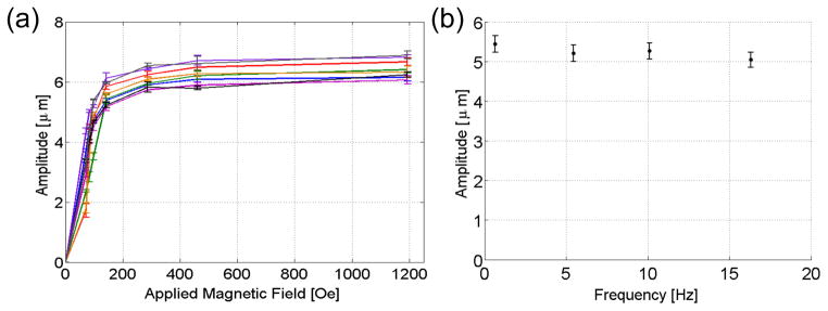
The rod amplitude is reproducible across an array, and increasing the actuation frequency results in a minimal decrease in rod amplitude and thus bend angle. (a) Measured amplitudes for eight rods (10 μm length, 550 nm diameter, LNi ≈ 3 μm) as a function of applied magnetic field; magnetic saturation of the Ni tubes begins around 1000 Oe. (b) Rod amplitude as a function of frequency for a low applied magnetic field of 110 Oe. The change in amplitude from the lowest to highest frequency is ~7%.
Obtaining the largest possible actuator response requires determination of the optimal magnetic loading for a given geometry. Several figures of merit have been developed to evaluate the responsiveness of an actuator [44–47]. We utilize an energy minimization model developed by Evans et al. that predicts the maximum bend angle given an actuator’s magnetization, elastic modulus, and magnetic loading [45, 48].
For a homogeneous material, such as the ferrofluid-PDMS (FFPDMS) material used for artificial cilia presented in our previous work [8, 45], the maximum bend angle of a rod-shaped actuator driven by the torque of an imposed magnetic field is [45, 48]
| (1) |
where M is the magnetization of the magnetic material used, E is the elastic modulus, f is the volume fraction or magnetic loading, μ0 is the permeability of free space, and L and r are the length and radius of the rod (see figure 1(d)). Note that ϕ is the static limit of the tilt angle θ in figure 1(d). Equation 1 assumes the magnetic torque on the actuator is maximized when the angle between the actuator and magnetic field direction is 45° [45]. The first factor in equation 1 accounts for the magnetic and elastic properties of the material, and the second factor considers the geometry of the rod-shaped actuator. Thus, for a given geometry, optimizing the static responsiveness is achieved by maximizing the first factor. For a more complete comparison among materials, we substitute the saturation magnetization Msat for M so we may consider the maximum actuation for a given choice of material. This is consistent with our experiments where a sufficiently large magnetic field strength is applied such that the magnetic material is saturated.
At first glance, it appears the best way to increase the responsiveness is by increasing the volume fraction f of magnetic material. However, for many composite materials, E increases when f is increased. Several models for the elastic modulus of a composite material demonstrate E’s parabolic dependence on f, indicating that E can grow much more quickly than f [49]. Because of this, the volume fraction of magnetic material in the FFPDMS we originally employed was kept below 0.04 [8]. Aggregation is also an issue when increasing f in homogeneous materials, though not accounted for in equation 1. Recent research has focused on the use of organic coatings to increase the magnetic loading without causing aggregation and an increased elastic modulus, though magnetic loading still only approaches 0.2 by volume [48].
The energy minimization model and subsequent bend angle prediction formula (equation 1) were designed for use with homogeneous materials as actuators, but we can apply this prediction to our core-shell rod system to both maximize its responsiveness and to compare it to other actuators. We first calculate the volume fraction of Ni by taking into account both the Ni tube length LNi and Ni tube thickness t:
| (2) |
As the portion of the rod surrounded by the Ni tube acts as a stiff projection from the rod’s soft PDMS base, we take L in equation 1 to be the length of the pure PDMS portion of the rod, LPDMS, which is equal to the total length of the rod L minus the nickel tube length LNi. The volume fraction in equation 2 is then substituted into equation 1,
| (3) |
and the bend angle for core-shell rods can be rearranged to
| (3) |
where r is the radius of the entire rod, L is the entire rod length, t is the tube thickness, Msat is the saturation magnetization of nickel, and the CS subscript indicates ϕ is for core-shell rods.
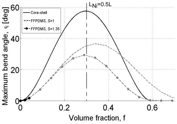
This result makes it clear that there is some length of the Ni tube that will optimize the actuator’s responsiveness. The elastic modulus E is also now uncoupled from f, changing only with choice of the polymer core, since solely the length of the PDMS portion changes as we change the Ni tube length. The maximum of ϕCS with respect to LNi occurs at LNi = 0.5L, which for our 10 μm rods is 5 μm. This Ni tube length, with a 100 nm tube thickness and 550 nm diameter, corresponds to a volume fraction of 0.30. Figure 8 shows the predicted bend angle for a given volume fraction with a rod diameter of 550 nm and Ni tube thickness t =100 nm; this actuator geometry is commonly utilized in our experiments. As figure 8 indicates, increasing the Ni tube length, which may be modified by altering the amount of charge deposited during electrodeposition (figure 2(b)), results in an increased responsiveness and larger bend angle. This gain in responsiveness occurs until the tube length is 5 μm, or f = 0.3, after which incorporating additional Ni begins to stiffen the rod. To continue increasing the bend angle by increasing LNi, a softer polymer could be used as the core material. For a core-shell rod with LNi = 2.8 μm (f = 0.167), the bend angle computed by the model is 37.3°. Converting the average amplitude near magnetic saturation in figure 7(a) (rods have LNi = 2.8±0.4 μm) to an average bend angle gives 39°±3° experimentally, which agrees with the model. For a core-shell rod with LNi = 3.6 μm (f = 0.214), the bend angle computed by the model is 48.8°; this value also agrees with the experimentally measured bend angle 46°±3° for rods with LNi = 3.6±0.2 μm.
Figure 8.
Core-shell rods are capable of achieving bend angles up to 50 times larger than experimentally viable FFPDMS rods. The core-shell actuator (solid line) achieves nearly twice the deflections of FFPDMS actuators which have either loosely (S = 1.0, dashed line) or tightly (S = 1.35, dashed-dotted line) packed filler particles, as defined in the Mooney equation (equation 5) where E(f = 0) = 2.5 Mpa [51]. The highest f for FFPDMS achieved thus far is f = 0.04; therefore, the FFPDMS curves have been grayed out to indicate possibly unachievable volume fractions. For the calculation of these curves, we assumed the literature values Msat,Ni = 5.22×10³ emu/cm3 [52] and Msat,maghemite = 3.43×10³ emu/cm3 [53], and ECS = 2.5 MPa.
In contrast to the nickel tube length, increasing the tube thickness always generates larger maximum applied force and larger bend angle as the tube thickness has no effect on flexibility. Using this model, decreasing the tube thickness from 100 nm to 75 nm changes the maximum bend angle from 57° to 36°; the bend angle increases to 80° when tube thickness becomes 125 nm. In addition, athough no longer a core-shell structure, at the limit such that the Ni tube becomes a solid rod with a diameter of 750 nm and optimum Ni length (LNi = 0.5L and f = 0.5), the maximum predicted bend angle is 87° when the Ni tube is magnetically saturated and the magnetic field is maintained at an angle of 45° with respect to the rod’s axis.
Also in figure 8, we plotted predicted bend angles for FFPDMS composite rods with identical rod length and diameter for comparison to the core-shell bend angles. For composite materials such as FFPDMS, small volume fractions are not thought to appreciably change the material’s elastic modulus. However, at some point material stiffness will be affected by increasing the concentration of rigid inclusions [49, 50]. In order to predict the elastic modulus as a function of volume fraction and compare maximum bend angles for larger volume fractions, we utilized a model applied by Mooney to rigid inclusions in a non-rigid matrix,
| (5) |
where Gc is the shear modulus of the composite material, Gm is the shear modulus of the matrix material, and S is the self-crowding factor (the volume that the inclusions occupy/the actual volume of the inclusions) [51]. If the spherical inclusions are tightly packed, S = 1.35; for loosely packed inclusions, S = 1. Equation 5 is typically used when the spherical inclusions are infinitely more rigid than the surrounding matrix. In FFPDMS, the maghemite particles have an elastic modulus 105 times greater than their PDMS matrix. Before substituting this relation for modulus into equation 1, we converted the shear modulus to the elastic modulus and varied the volume fraction from zero to 0.7, assuming a matrix modulus Em = 2.5 MPa and a Poisson ratio ν = 0.5. The crowding factors S = 1 and S = 1.35 are both plotted in figure 8 to illustrate upper and lower bounds for FFPDMS and thus the bend angle. Even when optimizing FFPDMS as a material, FFPDMS rods are only able to bend approximately half as much as core-shell rods. Note that for FFPDMS rods, even though the optimal volume fraction is 0.35, the highest volume fraction achieved thus far is 0.04 (indicated by the solid black portions of the curves), which limits the static actuation achievable. The entire core-shell curve is possible experimentally, thus no part of it has been grayed out.
As these experiments and model suggest, the core-shell rod is a highly responsive actuator, which is especially important in highly viscous and viscoelastic fluids, including biofluids such as blood, cerebrospinal fluid, and mucus. To further explore and manipulate higher viscosity fluids at the micron scale, several methods have been devised including silicon diffuser micropumps which utilize an oscillating diaphragm to move more viscous fluids (up to 900 cP) through a channel [54], oscillating bubbles generated by piezoelectric discs inside a channel to mix glycerol solutions of varying viscosities [55], and large magnetically-driven artificial ciliated structures that actively mix viscous fluids greater than 25 cP [30]. However, the pumping diaphragm requires cleanroom microfabrication techniques such as deep reactive ion etching, and the oscillating bubbles are capable of mixing fluids with viscosities only up to 45 cP [54]. In a 35 cP fluid, Chen et al. employed artificial cilia that mixed with an efficiency of 86%, though they are much larger than the core-shell rods presented here, 300 μm length by 50 μm diameter [30]. In our previous work, we reported on the ability of our artificial cilia arrays to pump and mix fluids, and the core-shell rods presented here are now poised to be applied for this same function in high viscosity fluids.
As an example of the capability of core-shell arrays to generate significant dynamic actuation in highly viscous environments, we conclude by demonstrating driven fluid flow in a viscoelastic fluid with viscosity over two orders of magnitude larger than water. We utilized agarose at a concentration of 0.1%, which is a viscoelastic fluid with a zero-shear viscosity of 490 cP (whereas water has a viscosity of 0.89 cP) and tanδ ~ 0.7 at a shear stress of 2 mPa oscillating at 1 Hz. At a shear stress of 1 Pa oscillating at 1 Hz, tanδ ~20. Agarose has been shown in the literature to exhibit gross viscoelastic properties similar to those of mucus present in the lung [56]. A moderate field strength was employed (~500 Oe), and the fluid was seeded with one micron carboxylate-modified red fluorescent microspheres (FluoSpheres, F-8821) to track the flow direction and velocity. We oriented the actuating magnet to drive the core-shell array in a beat pattern reminiscent of the ‘tilted conical beat’ employed by embryonic nodal cilia [31, 57], the parameters for which are described in figure 1(d). Actuation of the core-shell array at 16 Hz resulted in a maximum average amplitude of 3.9±0.8 μm (or bend angle of 23±5°), and 10 μm above the rod tips generated a flow with an average x-velocity of 1.7±1.2 μm/s and average y-velocity of 1±2 μm/s (video S4). We suspect both the elastic component of the fluid and inhomogeneities in rod density created during fluid exchange have an effect on tracer motion near the rod tips; this effect is evident from the velocity’s large standard deviation and the presence of small, local flows, as shown in figure 9(a). When the rods were motionless, we expected tracer motion to appear diffusive in nature. Figure 9(b) depicts the motion of the particles when rods were stationary. Treatment of the tracers as particles with non-zero velocities to ascertain the presence of a background flow resulted in an average x-velocity of 0.01±0.05 μm/s and y-velocity of 0.02±0.05 μm/s. This demonstration is the first example of a biomimetic cilia-like actuator on the scale of biological cilia which is capable of driving fluid flow in a viscoelastic fluid.
Figure 9.
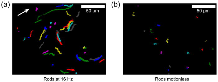
Core-shell rod actuation drives flow in the viscoelastic fluid agarose (0.1% concentration). (a) Trajectories of tracer particles 10 μm above the rod tips (z=20 μm) as driven by the core-shell array actuated at 16 Hz. Flow moves with an average x-velocity of 1.7±1.2 μm/s and an average y-velocity of 1±2 μm/s. White arrow indicates the average direction of tracer particles. (b) Tracer particle trajectories when rods are motionless.
In addition, increased responsiveness also corresponds to significant improvements in pumping performance in low viscosity fluids relative to other demonstrated cilia-like actuators. This corresponds to the fact that an increase in drive frequency up to 16 Hz results in little to no decrease in rod amplitude in low viscosity fluids (figure 7(b)). We actuated our core-shell arrays in Dulbecco’s Phosphate Buffered Saline (PBS), which has a zero-shear viscosity of 1.05 cP. In this fluid, the core-shell rods generated flow at the rod tips with an average speed of 19±7 μm/s with an experimental tilt angle of 29° and beat frequency of 16 Hz. For comparison, in our previous work with FFPDMS rods with a tilt angle of θ=30° and actuated at a frequency of 12 Hz in the same fluid viscosity, the array generated directed flow at a velocity of 4 μm/s just above the rod tips. The data suggest that such an array driven at 16 Hz would likely generate directed flow with a velocity of ~4.5 μm/s [31]. Also, Vilfan et al. reported magnetically linking paramagnetic beads and electromagnetically actuating them with a tilt angle of 40°, at a frequency of 1 Hz to produce flow velocities up to 4 μm/s [3]. The flow profile detailing the core-shell rod-driven velocity as a function of height within the flow cell is shown in figure S1.
In summary, we have developed a fabrication strategy for the production of large arrays of highly responsive core-shell microrods, the size of which are comparable to biological cilia. By altering the length and thickness of the Ni shell, the magnetic and elastic properties may be tuned for use in specific applications. In addition, we have demonstrated that these arrays can be actuated by permanent magnets though 90° bend angles and have the capability to generate directed flow in both aqueous and highly viscous fluids. Future work will utilize these core-shell microrod arrays as a model system for mucociliary transport in the airways in order to experimentally explore cilia-driven viscoelastic fluid transport.
Supplementary Material
Acknowledgments
The authors thank Dr. Frank Tsui and Matthew Wolboldt of UNC-Chapel Hill for their assistance with SQUID measurements. This work was supported by a National Institute of Environmental Health Sciences (NIEHS) grant, 1-RC1-ES018686. B. L. Fiser, A. R. Shields, and R. Superfine are inventors on United States Patent No. 8,586,368 entitled “Methods and systems for using actuated surface-attached posts for assessing biofluid rheology”; this patent was granted Nov 19, 2013.
Footnotes
SUPPORTING INFORMATION AVAILABLE: Videos of actuating core-shell microrods, a figure detailing the rod-driven flow profile in PBS, and the treatment of core-shell rods as simple harmonic oscillators are contained in the Supporting Information.
References
- 1.Furst EM, Suzuki C, Fermigier M, Gast AP. Permanently linked monodisperse paramagnetic chains. Langmuir : the ACS journal of surfaces and colloids. 1998;14:7334–6. [Google Scholar]
- 2.Singh H, Laibinis PE, Hatton TA. Synthesis of flexible magnetic nanowires of permanently linked core-shell magnetic beads tethered to a glass surface patterned by microcontact printing. Nano Letters. 2005;5:2149–54. doi: 10.1021/nl051537j. [DOI] [PubMed] [Google Scholar]
- 3.Vilfan M, Potočnik A, Kavčič B, Osterman N, Poberaj I, Vilfan A, Babič Da. Self-assembled artificial cilia. Proceedings of the National Academy of Sciences of the United States of America. 2010;107:1844–7. doi: 10.1073/pnas.0906819106. [DOI] [PMC free article] [PubMed] [Google Scholar]
- 4.Judy JW, Muller RS, Zappe HH. Magnetic microactuation of polysilicon flexure structures. Journal of Microelectromechanical Systems. 1995;4:162–9. [Google Scholar]
- 5.Khoo M, Liu C. Micro magnetic silicone elastomer membrane actuator. Sensors and Actuators A. 2001;89:259–66. [Google Scholar]
- 6.Kudo H, Sawada T, Kazawa E, Yoshida H, Iwasaki Y, Mitsubayashi K. A flexible and wearable glucose sensor based on functional polymers with soft-mems techniques. Biosensors & bioelectronics. 2006;22:558–62. doi: 10.1016/j.bios.2006.05.006. [DOI] [PubMed] [Google Scholar]
- 7.Liu C. Development of surface micromachined magnetic actuators using electroplated permalloy. Mechatronics. 1998;8:613–33. [Google Scholar]
- 8.Evans BA, Shields AR, Carroll RL, Washburn S, Falvo MR, Superfine R. Magnetically actuated nanorod arrays as biomimetic cilia. Nano Letters. 2007;7:1428–34. doi: 10.1021/nl070190c. [DOI] [PubMed] [Google Scholar]
- 9.Fahrni F, Prins MWJ, van Ijzendoorn LJ. Micro-fluidic actuation using magnetic artificial cilia. Lab on a chip. 2009;9:3413–21. doi: 10.1039/b908578e. [DOI] [PubMed] [Google Scholar]
- 10.Fuhrer R, Athanassiou EK, Luechinger NA, Stark WJ. Crosslinking metal nanoparticles into the polymer backbone of hydrogels enables preparation of soft, magnetic field-driven actuators with muscle-like flexibility. Small. 2009;5:383–8. doi: 10.1002/smll.200801091. [DOI] [PubMed] [Google Scholar]
- 11.Hussong J, Schorr N, Belardi J, Prucker O, Ruhe J, Westerweel J. Experimental investigation of the flow induced by artificial cilia. Lab on a chip. 2011;11:2017–22. doi: 10.1039/c0lc00722f. [DOI] [PubMed] [Google Scholar]
- 12.Olsson RT, Samir MASA, Salazar-Alvarez G, Belova L, Ström V, Berglund LA, Ikkala O, Nogués J, Gedde UW. Making flexible magnetic aerogels and stiff magnetic nanopaper using cellulose nanofibrils as templates. Nature Nanotechnology. 2010;5:584–8. doi: 10.1038/nnano.2010.155. [DOI] [PubMed] [Google Scholar]
- 13.Pirmoradi F, Cheng L, Chiao M. A magnetic poly(dimethylesiloxane) composite membrane incorporated with uniformly dispersed, coated iron oxide nanoparticles. Journal of Micromechanics and Microengineering. 2010;20:015032. [Google Scholar]
- 14.Cao H, Tie C, Xu Z, Hong J, Sang H. Array of nickel nanowires enveloped in polyaniline nanotubules and its magnetic behavior. Applied Physics Letters. 2001;78:1592. [Google Scholar]
- 15.Li L, Yang Y-W, Li G-H, Zhang L-D. Conversion of a bi nanowire array to an array of bi-bi2o3 core-shell nanowires and bi2o3 nanotubes. Small. 2006;2:548–53. doi: 10.1002/smll.200500382. [DOI] [PubMed] [Google Scholar]
- 16.Mekki A, Samanta S, Singh A, Salmi Z, Mahmoud R, Chehimi MM, Aswal DK. Core/shell, protuberance-free multiwalled carbon nanotube/polyaniline nanocomposites via interfacial chemistry of aryl diazonium salts. Journal of Colloid and interface Science. 2014;418:185–92. doi: 10.1016/j.jcis.2013.11.077. [DOI] [PubMed] [Google Scholar]
- 17.Park S, Hong T, Jung J, Lee C. Room temperature hydrogen sensing of multiple networked zno/wo3 core-shell nanowire sensors under uv illumination. Current Applied Physics. 2014;14:1171–5. [Google Scholar]
- 18.Lahav M, Weiss EA, Xu Q, Whitesides GM. Core-shell and segmented polymer-metal composite nanostructures. Nano Letters. 2006;6:2166–71. doi: 10.1021/nl061786n. [DOI] [PMC free article] [PubMed] [Google Scholar]
- 19.Pol VG, Pol SV, Gedanken A. Core-shell nanorods of sns-c and snse-c: Synthesis and characterization. Langmuir : the ACS journal of surfaces and colloids. 2008;24:5135–9. doi: 10.1021/la7040532. [DOI] [PubMed] [Google Scholar]
- 20.Evans PR, Hendren WR, Atkinson R, Pollard RJ. Nickel-coated gold-core nanorods produced by template assisted electrodeposition. Journal of The Electrochemical Society. 2007;154:K79–K82. [Google Scholar]
- 21.Kim Y-S, Ahn H-J, Nam SH, Lee SH, Shim H-S, Kim WB. Honeycomb pattern array of vertically standing core-shell nanorods: Its application to li energy electrodes. Applied Physics Letters. 2008;93:103104. [Google Scholar]
- 22.Liu Z, Xia G, Zhu F, Kim S, Markovic N, Chien C-L, Searson PC. Exploiting finite size effects in a novel core/shell microstructure. Journal of Applied Physics. 2008;103:064313. [Google Scholar]
- 23.Peng X, Jin J, Ichinose I. Mesoporous separation membranes of polymer-coated copper hydroxide nanostrands. Advanced Functional Materials. 2007;17:1849–55. [Google Scholar]
- 24.Liu M, Liu X, Wang J, Wei Z, Jiang L. Electromagnetic synergetic actuators based on polypyrrole/fe3o4 hybrid nanotube arrays. Nano Research. 2010;3:670–5. [Google Scholar]
- 25.Nielsch K, Castaño FJ, Ross CA, Krishnan R. Magnetic properties of template-synthesized cobalt/polymer composite nanotubes. Journal of Applied Physics. 2005;98:034318. [Google Scholar]
- 26.van Oosten CL, Bastiaansen CWM, Broer DJ. Printed artificial cilia from liquid-crystal network actuators modularly driven by light. Nature Materials. 2009;8:677–82. doi: 10.1038/nmat2487. [DOI] [PubMed] [Google Scholar]
- 27.den Toonder J, et al. Artificial cilia for active micro-fluidic mixing. Lab on a chip. 2008;8:533–41. doi: 10.1039/b717681c. [DOI] [PubMed] [Google Scholar]
- 28.Pokroy B, Epstein AK, Persson-Gulda MCM, Aizenberg J. Fabrication of bioinspired actuated nanostructures with arbitrary geometry and stiffness. Advanced Materials. 2009;21:463–9. [Google Scholar]
- 29.Oh K, Smith B, Devasia S, Riley JJ, Chung J-H. Characterization of mixing performance for bio-mimetic silicone cilia. Microfluidics and Nanofluidics. 2010;9:645–55. [Google Scholar]
- 30.Chen C-Y, Chen C-Y, Lin C-Y, Hu Y-T. Magnetically actuated artificial cilia for optimum mixing performance in microfluidics. Lab on a chip. 2013;13:2834–9. doi: 10.1039/c3lc50407g. [DOI] [PubMed] [Google Scholar]
- 31.Shields AR, Fiser BL, Evans BA, Falvo MR, Washburn S, Superfine R. Biomimetic cilia arrays generate simultaneous pumping and mixing regimes. Proceedings of the National Academy of Sciences of the United States of America. 2010;107:15670–5. doi: 10.1073/pnas.1005127107. [DOI] [PMC free article] [PubMed] [Google Scholar]
- 32.Smith DJ, Blake JR, Gaffney EA. Fluid mechanics of nodal flow due to embryonic primary cilia. Journal of the Royal Society Interface. 2008;5:567–73. doi: 10.1098/rsif.2007.1306. [DOI] [PMC free article] [PubMed] [Google Scholar]
- 33.Kumar S, Kumar S, Chakarvarti SK. Sem morphology and xrd characterization of ni microstructure arrays synthesized by dc electrodeposition in porous polycarbonate templates. Journal of Materials Science. 2004;39:3249–51. [Google Scholar]
- 34.Roca-Cusachs P, Rico F, Martinez E, Toset J, Farré R, Navajas D. Stability of microfabricated high aspect ratio structures in poly (dimethylsiloxane) Langmuir : the ACS journal of surfaces and colloids. 2005;21:5542–8. doi: 10.1021/la046931w. [DOI] [PubMed] [Google Scholar]
- 35.Zhang Y, Lo C, Taylor J, Yang S. Replica molding of high-aspect-ratio polymeric nanopillar arrays with high fidelity. Langmuir : the ACS journal of surfaces and colloids. 2006;22:8595–601. doi: 10.1021/la061372+. [DOI] [PubMed] [Google Scholar]
- 36.Cordente N, Respaud M, Senocq F, Casanove M-J, Amiens C, Chaudret B. Synthesis and magnetic properties of nickel nanorods. Nano Letters. 2001;1:565–8. [Google Scholar]
- 37.Ferré F, Ounadjela K, George JM, Piraus L, Dubois S. Magnetization processes in nickel and cobalt electrodeposited nanowires. Physical Review B. 1997;56:14066–75. [Google Scholar]
- 38.Kisker H, Gessmann T, Würschum R, Kronmüller H, Schaefer H-E. Magnetic properties of high purity nanocrystalline nickel. NanoStructured Materials. 1995;6:925–8. [Google Scholar]
- 39.Bao J, Tie C, Xu Z, Zhou Q, Shen D, Ma Q. Template synthesis of an array of nickel nanotubules and its magnetic behavior. Advanced Materials. 2001;13:1631–3. [Google Scholar]
- 40.Tao F, Guan M, Jiang Y, Zhu J, Xu Z, Xue Z. An easy way to construct an ordered array of nickel nanotubes: The triblock-copolymer-assisted hard-template method. Advanced Materials. 2006;18:2161–4. [Google Scholar]
- 41.Chikazumi S. Physics of magnetism. New York: Wiley; 1964. [Google Scholar]
- 42.Xue S, Cao C, Zhu H. Electrochemically and template-synthesized nickel nanorod arrays and nanotubes. Journal of Materials Science. 2006;41:5598–601. [Google Scholar]
- 43.Encinas-Oropesa A, Demand M, Piraux L, Ebels U, Huynen I. Effect of dipolar interactions on the ferromagnetic resonance properties in arrays of magnetic nanowires. Journal of Applied Physics. 2001;89:6704. [Google Scholar]
- 44.Cebers A. Flexible magnetic filaments. Current Opinion in Colloid & Interface Science. 2005;10:167–75. [Google Scholar]
- 45.Evans BA, Superfine R. In: Biomimetic based applications. George A, editor. Croatia: Intech; 2011. [Google Scholar]
- 46.Gauger EM, Downton MT, Stark H. Fluid transport at low reynolds number with magnetically actuated artificial cilia. The European Physical Journal E. 2009;28:231–42. doi: 10.1140/epje/i2008-10388-1. [DOI] [PubMed] [Google Scholar]
- 47.Roper M, Dreyfus R, Baudry J, Fermigier M, Bibette J, Stone HA. On the dynamics of magnetically driven elastic filaments. Journal of Fluid Mechanics. 2006;554:167–90. [Google Scholar]
- 48.Evans BA, Fiser BL, Prins WJ, Rapp DJ, Shields AR, Glass DR, Superfine R. A highly tunable silicone-based magnetic elastomer with nanoscale homogeneity. Journal of Magnetism and Magnetic Materials. 2012;324:501–7. doi: 10.1016/j.jmmm.2011.08.045. [DOI] [PMC free article] [PubMed] [Google Scholar]
- 49.Ahmed S, Jones FR. A review of particulate reinforcement theories for polymer composites. Journal of Materials Science. 1990;25:4933–42. [Google Scholar]
- 50.Guild FJ, Young RJ. A predictive model for particulate-filled composite materials. Journal of Materials Science. 1989;24:298–306. [Google Scholar]
- 51.Mooney M. The viscosity of a concentrated suspension of spherical particles. Journal of Colloid Science. 1951;6:162–70. [Google Scholar]
- 52.Danan H, Herr A, Meyer JP. New determinations of the saturation magnetization of nickel and iron. Journal of Applied Physics. 1968;39:669–70. [Google Scholar]
- 53.Evans BA. Design, fabrication, and actuation of biomimetic cilia. Chapel Hill: University of North Carolina at Chapel Hill; 2008. [Google Scholar]
- 54.Andersson H, van der Wijingaart W, Nilsson P, Enoksson P, Stemme G. A valve-less diffuser micropump for microfluidic analytical systems. Sensors and Actuators B. 2001;72:259–65. [Google Scholar]
- 55.Wang S, Huang X, Yang C. Mixing enhancement for high viscous fluids in a microfluidic chamber. Lab on a chip. 2011;11:2081–7. doi: 10.1039/c0lc00695e. [DOI] [PubMed] [Google Scholar]
- 56.King M, Gilboa A, Meyer FA, Silberberg A. On the transport of mucus and its rheologic simulants in ciliated systems. American Review of Respiratory Disease. 1974;110:740–5. doi: 10.1164/arrd.1974.110.6P1.740. [DOI] [PubMed] [Google Scholar]
- 57.Hirokawa N, Okada Y, Tanaka Y. Fluid dynamic mechanism responsible for breaking the left-right symmetry of the human body: The nodal flow. Annual Review of Fluid Mechanics. 2009:4153–72. [Google Scholar]
Associated Data
This section collects any data citations, data availability statements, or supplementary materials included in this article.


