

Abstract
We describe a MRI-compatible biopsy needle instrumented with optical fiber Bragg gratings for measuring bending deflections of the needle as it is inserted into tissues. During procedures, such as diagnostic biopsies and localized treatments, it is useful to track any tool deviation from the planned trajectory to minimize positioning errors and procedural complications. The goal is to display tool deflections in real time, with greater bandwidth and accuracy than when viewing the tool in MR images. A standard 18 ga × 15 cm inner needle is prepared using a fixture, and 350-μm-deep grooves are created along its length. Optical fibers are embedded in the grooves. Two sets of sensors, located at different points along the needle, provide an estimate of the bent profile, as well as temperature compensation. Tests of the needle in a water bath showed that it produced no adverse imaging artifacts when used with the MR scanner.
Index Terms: Biomedical transducers, biopsy, Bragg gratings, magnetic resonance imaging (MRI), optical fiber sensors, strain measurement
I. Introduction
Magnetic resonance imaging (MRI)-guided interventions have become increasingly popular for minimally invasive treatments and diagnostic procedures. Dynamic tool-tracking and scan-plane control are not widely implemented in practice, and current hardware and software capabilities of MRI systems result in iterative processes of moving the patient in and out of the scanner for imaging and intervention [7], [23]. Furthermore, clear visualization of the entire minimally invasive tool and its intended trajectory is not always available intraoperatively through MR images.
During MRI-guided breast and prostate biopsies, radiologists note mild-to-significant needle bending. Various in vitro and simulated studies have characterized needle deflection as a function of insertion depth, needle gauge, and insertion force [1], [20]. Wan et al. performed insertion depth experiments with an 18-ga 20-cm bevel-tipped brachytherapy needle and found that needle deflection contributes to the main source of seed placement error (up to 2.8 mm) for an insertion depth of 6 cm [41]. Hochman and Friedman characterized tip deflections of 25-, 27-, and 30-ga needles in various materials and showed that deflections ranged from 0.7 to 5.0 mm [16]. When steering around obstacles, tip deflections can be up to 2 cm for a 20-ga 15-cm biopsy needle [9]. These deflections may necessitate reinserting the needle to reach a desired target. Although real-time MR images can provide visual feedback, their low spatial resolution and relatively low contrast resolution [28] make it difficult to identify the exact tip deflections.
Methods in active tracking of devices in MRI environments [6], [11], [18], [37] are increasingly fast and accurate, yet these techniques, as reviewed in [7], have limitations in regard to line-of-sight, heating, sensitive tuning, complex calibration, and expense. Passive tracking methods [8] rely on observing the device and patient’s anatomy together with the use of bulky stereotactic frames or external fiducials [13], [21]. Also, they require manual retrieval of the passive markers in the image data and calculation of the needle position. The planning, adjustment, and starting of MR scans typically need to be performed manually [42]. The use of RF coils [26] and rapid MR-tracking [22] techniques are also limited by the need for continual use of the scanner in order to image and visualize the devices. Another issue with current tracking methods is that they require sensors that are in general too large for incorporation in a needle [2]. The prototype presented here uses miniature sensors, does not rely on continual imaging, and has a simple registration procedure, in order to track tools in real time and enable faster physician response.
This paper describes a prototype instrumented needle that incorporates optical fibers with fiber Bragg gratings (FBGs) for measuring strain. FBG cells reflect light with a peak wavelength that shifts in proportion to the strain to which they are subjected [15]. In other applications, FBG sensors have been embedded into force-sensing robot fingers [30], [33], [34], and integrated into catheters [12] and endoscopes [43] for shape sensing. FBG sensors have also been used to measure forces of a retinal surgery tool [19], [38]. To our knowledge, the prototype presented here is the first application of FBG sensing in a small-gauge MRI-compatible biopsy needle.
Among the advantages of FBG sensors are: immunity to electromagnetic interference (making them ideal of MR applications), physical robustness (without compromising the biocompatibility and sterilizability of the medical tools they modify), and the ability to detect strains as small as 0.1 με. As a consequence of their ability to measure small strains, FBG sensors can be used directly on relatively robust structures, without special features, such as holes or slots, to increase strains in the vicinity of the gauge. Other advantages include the ability to place multiple FBG cells along a single fiber, reading each via optical multiplexing, and the ability to use the same optical fibers for other sensing and imaging modalities, such as spectroscopy [40], optical coherence tomography, and fluoroscopy. The FBG wavelength shifts are also dependent on temperature changes; thus, the sensors have applications in thermal therapies, such as cryosurgery and tissue ablation procedures. In conventional robotics applications, the chief drawback is that the optical interrogator that reads the signals from the FBG cells is larger and much more expensive than the instrumentation used for foil or semiconductor strain gauges. However, the costs of optical-fiber interrogation systems are dropping steadily and in applications, such as MRI interventions, the capital costs are amortized over many operations.
Although FBG sensors are a mature technology, innovations in photonics are making it possible to read larger numbers of cells at higher sampling rates and with smaller and less expensive equipment. In this study, we use a broadband light source and optical wavelength division multiplexing (Intelligent Fiber Optic Systems (IFOS) Corp., Santa Clara, CA) so that all FBGs are read simultaneously. The optical interrogator computes shifts in the wavelength of light returned by each FBG, and reports these over a universal serial bus (USB) connection to our computer for calibration and visualization. We have presented the feasibility of using FBG sensors in MR-interventions [31], [32] and, in this paper, present the design and testing of an MRI-compatible biopsy needle with embedded fibers for real-time shape detection.
The needle prototype is an early step toward increased integration of sensing and visualization of MRI-compatible medical devices. The goal is to display tool deflections in real time, with greater bandwidth and accuracy than available when purely viewing the tool in MR images. We believe that it has the potential for more accurate MRI interventions, with a reduced need to cycle the patient into and out of the MRI machine.
II. System Modeling
Forces on a needle during insertion have been modeled as a combination of frictional forces opposing insertion, clamping forces applied by the surrounding tissue, and an axial tip force [1], [10]. The models assume predominant forces close to the tip (primarily due to tissue cutting). Since we are interested in measuring needle deflections, we can apply forces that produce deflections similar to those observed in practice when evaluating the accuracy of the sensors.
An example simulation of a needle being steered toward a target is illustrated in [9, Fig. 17]. The deflection profile of the 18-ga needle in that figure is comparable to those obtained with simplified force profiles, such as those shown in Figs. 1 and 3. Due to the stiffness of the needle, the effects of any concentrated forces are spread out over a substantial fraction of the length of the needle.
Fig. 1.
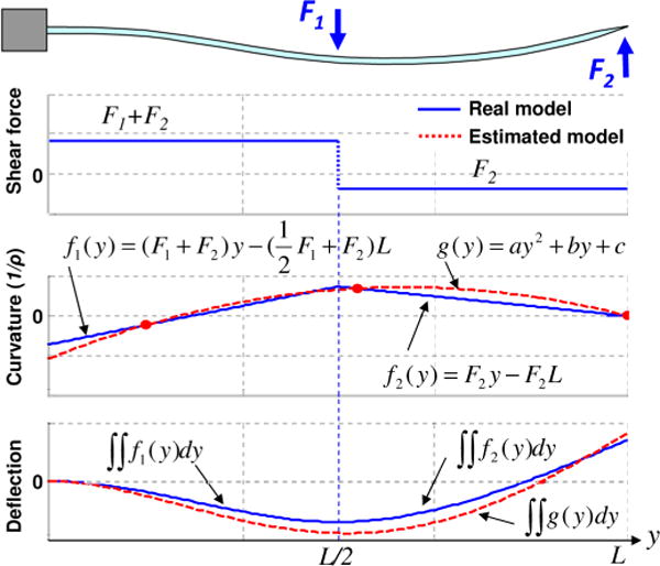
Example of deflection estimation process based on beam theory. A needle is fixed at the base (y = 0 mm), and two point loads of −0.6 N and 0.2 N are applied at the midpoint (y = 75 mm) and at the tip (y = 150 mm) of the needle, respectively. The shaded dots in the curvature plot are sensor locations, which lead to an estimate for g(y).
Fig. 3.
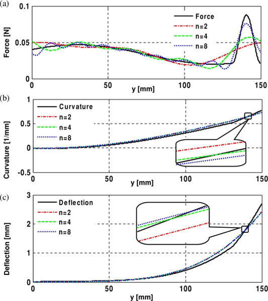
(a) Force profile approximated with Fourier series with different numbers of terms. (b) Curvature profile—first integral of the force profile. (c) Deflection profile—second integral of curvature profile. The insets show the curvature and the deflection profiles are quite similar.
A. Modeling Assumptions
Considering the dimensions and mechanical properties of the needles, and the loading conditions anticipated during interventions in prostate or breast tissue, the following simplifying assumptions are used in the analysis of the prototype presented here.
The needle experiences negligible torsional loading along the needle length axis.
The tip deflection is relatively small – less than 10% of the needle length—such that small-strain linear beam theory [39] applies.
The needle is sufficiently stiff that the bent profile is not complex; there are at most one or possibly two points of inflection.
Given these assumptions, the needle is modeled as a slender cantilever beam, supported at one end and subjected to combinations of radial and axial forces. The boundary conditions are summarized in Table I. Fig. 1 illustrates a simplified loading example with two concentrated vertical forces at the midpoint and tip of the beam. (in practice, a significant force at the tip is possible, but a concentrated force at midspan is unlikely.) If there are two sensors, it is possible to obtain the beam curvature at two locations. In addition, the curvature at the tip must be zero, unless there is a concentrated end moment, which is physically unlikely. Given that the curvature of the beam must be smooth and continuous, a second-order polynomial g(y) can be fit to the three known curvatures. The corresponding deflection profile computed from g(y) is depicted in the bottom plot, in comparison to the actual profile that would be obtained directly from F1 and F2, assuming they were known. As discussed in the Section IV, the errors associated with less concentrated forces will typically be smaller.
TABLE I.
Boundary Conditions Used for Needle Deflection Estimation Based on Beam Theory
| Assumption | Boundary Conditionsa |
|---|---|
| The deflection at the base is zero. | Dxy(0) = Dyz(0) = 0 |
| The slope at the base is zero. | θxy(0) = θyz(0) = 0 |
| The curvature at the tip is zero. | gxy(L) = gyz(L) = 0 |
Dxy(y) and Dxy(y) are the deflection functions, θxy(y) and θxy(y) are the slope functions, and gxy(y) and gxy(y) are the curvature functions, in x–y and y–z planes, respectively. L is the length of the needle.
B. Optical Sensor Model
Local curvatures using strain information are obtained from the sensor signals. Since the Bragg wavelength λb is
| (1) |
where neff is the effective refractive index and Λ is the period of the grating, the relationship between the wavelength shift ΔλB and the strain ε can be expressed by
| (2) |
where Pε is the photoelastic coefficient of the optical fiber.
For a cylindrical rod under pure bending [14],
| (3) |
where d is the distance to the neutral plane, ρ is the radius of the curvature, and C is the relative curvature. The relationship between the wavelength shift and the curvature is then
| (4) |
Since Pε, neff, Λ, and d are all constants, the wavelength shift Δλb is linearly proportional to the curvature C. Therefore, given the amount of known curvature, a polynomial fit function can be derived. The second integral of the curvature function with the aforementioned boundary conditions gives the estimated deflection equation.
III. Prototype Design and Fabrication
An Food and Drug Administration (FDA)-approved 18 ga × 15 cm MRI-compatible histology biopsy needle (model number: MR1815, E-Z-EM Inc, Westbury, NY) was selected as a basis for prototyping. 18 ga is a typical size used for MRI-guided interventions, such as breast and prostate biopsies. This needle is composed of two parts, a solid inner needle (stylet), and a hollow outer needle (sheath). The outer needle is a thin-walled tube made of nonmagnetic nickel-cobalt-chromium-molybdenum alloy (MP35N). The inner stylet has a core of nickel-chromium-molybdenum alloy (Inconel 625). The stylet initially stays inside the outer sheath to prevent unwanted tissue or fluid from flowing into the bore, and to stiffen the needle during insertion. When the needle tip reaches the suspect tissue, the inner stylet is removed, and a syringe or other extraction mechanism is connected to the base of the sheath to remove the targeted cells. Although the removal of the inner stylet may cause slight bending of the outer sheath, the tip of the needle remains anchored within the same tissue once the tip hits the target. Thus, it is particularly useful to provide real-time feedback on needle bending during insertion.
Optical fibers were incorporated into the inner stylet, rather than the outer sheath, for two primary reasons: the wall of the outer needle is too thin for embedding optical fibers, and connecting the optical fiber cables at the stylet base does not interfere with tissue extraction, as it is removed prior to attaching a syringe or other tool.
A. Inner Stylet Design
The modified stylet has three grooves along the needle axis at 120° intervals, with three optical fibers attached inside the grooves. The minimum number of strain sensors required to estimate local curvatures at a particular location along the needle is two: one to measure bending in the x–y plane and the other for the y–z plane (see Fig. 2). However, it is necessary to provide temperature compensation because FBG sensors have high sensitivity to changes in temperature [29]. In the present case, since the diameter of the inner stylet is small (1 mm), we can assume that the temperature is uniform across the needle diameter. If we incorporate three FBGs at one location along the needle, we have one redundant sensor reading that we can use for temperature compensation. In addition, since each optical fiber contains two FBG sensors for strain measurement at two locations, there are a total of six FBG sensors (two sets of three sensors).
Fig. 2.
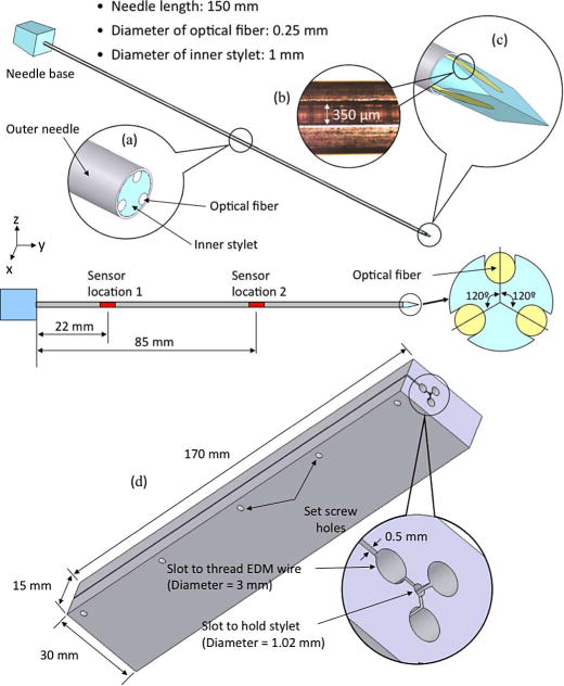
Prototype design with modified inner stylet incorporated with three optical fibers. Three identical grooves at 120° intervals are made on the inner stylet to embed optical fibers with FBGs along the needle length. (a) Midpoint cross section. (b) Magnified view of an actual groove. (c) Tip of the stylet. (d) Fixture design for EDM parallel grooves in the biopsy needle stylet.
As shown in Fig. 2, the inner stylet has three lengthwise grooves, 350 μm wide, separated at 120° intervals. Each groove holds an optical fiber with two FBG sensors at 22 mm and 85 mm from the base of the needle.
B. Fabrication
The grooves in the needle are manufactured using electrical discharge machining (EDM) along the stylet. EDM is ideal for this application, as it can create very small features with high accuracy in any metal, and does not run the risk of introducing ferromagnetic particles. To ensure accuracy, and to simplify the process of preparing multiple needles, we used a custom clamping fixture, which is also made by wire EDM, as shown in Fig. 2(d). The stylet is placed in the central 1.02-mm bore and clamped in place using several set screws. EDM wire is threaded into each of the larger 3-mm holes for cutting the corresponding groove. In future, if it becomes desirable to work with smaller needles, optical fibers as thin as 40 μm diameter and corresponding thinner EDM wires can be used.
A magnified view of a single groove is shown in the inset in Fig. 2(b). Optical fibers with an outer diameter of 350 μm were bonded in these grooves using a low-viscosity biocompatible cyanoacrylate adhesive. Since the contact area between an optical fiber and the groove surface is large, we expect good shear transfer between the needle and fibers.
Since EDM machining cannot cut plastic parts, the plastic handle was removed from the stylet using a heat gun and reattached using epoxy after machining. Holes were prepared in the plastic base, through which the optical fibers could exit. The fibers protruding from the base were jacketed for increased durability along their runs back to the optical interrogator.
IV. Sensor Placement
In general, as the needle is inserted into tissue, complex distributions of radial and axial forces may be imposed along its length. In addition, it is likely that there will be relatively large radial and axial forces concentrated near the tip. Such force profiles can be represented using Fourier series, if sufficient numbers of terms are taken. For example, Fig. 3 shows a possible combination of forces, including a distributed force profile along the needle and a somewhat concentrated force near the tip, approximated by Fourier series with eight, four, and two terms. Although the truncated series do not accurately capture the details of the profile, the corresponding curvature and deflection functions computed using them are similar to those computed from the original force distribution. This is because the stiffness of the needle causes it to act as a spatial low-pass filter with respect to any forces with high spatial frequency.
In light of this effect, a relatively small number of sensor locations can be sufficient to capture the needle profile, even for complex force distributions. The prototype described in Section III has just two sensor locations. Therefore, it is of interest to determine for this prototype what errors may be expected in the computed profile and where the sensors should be located to minimize those errors for anticipated loading conditions.
From the Nyquist–Shannon sampling theorem, we expect that two sensor locations will be the minimum number sufficient for a radial force profile whose period is greater than the needle length. To examine the effects of various possible force distributions, a Monte Carlo simulation of applied forces was conducted, and the corresponding needle profiles were computed for two sets of sensors, at locations y1 and y2. The distributed forces along the needle were represented as a series of radial impulses, at any orientation in the (x, z) plane and located at intervals of L/10 anywhere along the needle, with an impulse amplitude of 0–0.07 N. A concentrated axial and radial force with maximum magnitudes of 0.1 N could also be applied. For all such loading profiles, the needle undergoes at most one curvature inflection. The error in the needle tip location is typically of the most concern (and will often be largest because the curvature must be integrated along the needle from base to tip). Therefore, the sensor locations that produce the least tip error were tabulated. Fig. 4 shows the regions for locating the first and second sets of sensors that produce the smallest tip location errors.
Fig. 4.
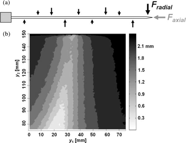
(a) Randomized force profiles with concentrated radial and axial tip forces. (b) Average tip deflection error plot with all possible sensor locations in a Monte Carlo simulation. The brighter region gives the lower tip deflection errors. (y1 and y2 are the locations of first and second set of sensors, respectively.)
V. Sensor Accuracy and Calibration
The needle prototype was calibrated for 3-D bending using two digital cameras. The cameras were fixed in two orthogonal planes and various deflections applied while images were taken in the x–y and y–z planes. The images were processed using the OpenCV [3] library to obtain the profile of the centerline of the needle. The resolution of the digital imaging system used for the calibration was 0.05 mm/pixel. The maximum optical distortion was less than 0.35%.
Three separate experiments were conducted for sensor calibration:
only vertical (z-axis) loads were applied;
only horizontal (x-axis) loads were applied;
only temperature was changed. The temperature at each sensor location was increased from 20 °C to 55 °C and decreased back to 20 °C. During this interval, the external temperature was measured using a digital temperature probe, and no mechanical load was applied to the needle.
Knowing that FBG wavelength shift is linearly proportional to curvature at the sensor location, as discussed in Section II, we can find a linear mapping between the two variables. Fig. 5 shows the calibration results from experiments 1), 2), and 3), respectively. All six FBG sensors provided linear and consistent signals. The maximum errors of local curvature measurement from the six sensors are: 2.14%, 0.14%, 0.65%, 0.27%, 0.35%, and 0.70%, respectively, for x-axis loading, and 0.06%, 0.19%, 0.21%, 0.05%, 0.19%, and 0.18%, respectively, for z-axis loading. As discussed in Section VIII, the relatively large error for sensor 1 for loading in the x-direction is likely due to a manufacturing error regarding the FBG placement in the needle; since it is consistent, the effect can be reduced via calibration.
Fig. 5.
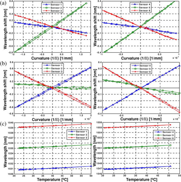
Curvature and temperature change calibration results. (a) Experiment 1 (x-axis loading). (b) Experiment 2 (z-axis loading). (c) Experiment 3 (temperature change)
Using the measured sensor signals and curvatures, we can determine a calibration matrix Cn for a sensor location n, when yn and sn are the measured reference and sensor signal, respectively,
| (5) |
where δyn = [kxy kyz Δt] and δsn = [Δλ1 Δλ2 Δλ3]. kxy and kyz are the local curvatures in x–y and y–z planes, Δt is the temperature change measured for temperature compensation, and Δλ1, Δλ2, and Δλ3 are wavelength shifts from the three FBGs at one location.
A simple way to solve for Cn is using the Moore-Penrose pseudoinverse
| (6) |
and the error in curvature measurement and temperature change at sensor location n is
| (7) |
However, the accuracy levels of curvature measurement and temperature change are different, and we have to normalize the error level using a weighting matrix [17].
The normalized error ẽ can be written as
| (8) |
where G is a scaling matrix [25]. Then, we minimize the normalized error
| (9) |
where W is a diagonal weight matrix. The scaling matrix, which determines the weight matrix, was determined by normalizing the variances of the errors on curvature and temperature change measurements in the experiments. Finally, we can find the weighted least squares solution for the calibration matrix as follows:
| (10) |
Since we have two sensor locations (22 mm and 85 mm from the base of the needle), a calibration matrix was found at each sensor location
Using the calibration matrix for each sensor location, we can find local curvatures from real-time sensor signals during the procedure. From the curvature measurements, we estimate the deflection profile using beam theory. This approach yielded rms values of tip deflection errors of 0.38 mm and 0.28 mm in the x–y and y–z planes, respectively, when the actual deflections were in the range of ±15 mm. Table II summarizes the tip deflection errors for different deflection ranges. Note that although the forces in this example were tip loads, no assumption about the loading was made in computing the profiles or deflections. As expected, the errors slightly decrease, as the deflection range decreases. The accuracy of the estimated fit to arbitrary bending profiles and over a wider range of temperatures will be further investigated in the future.
TABLE II.
Tip Deflection Error Comparison for Different Tip Deflection Ranges
| Deflection Range (mm) | −7≤ d ≤7 | −10≤ d ≤10 | −15≤ d≤15 |
|---|---|---|---|
| RMS of εxy | 0.35 | 0.38 | 0.38 |
| RMS of εyz | 0.26 | 0.26 | 0.28 |
The main error in estimating tip deflections with this method may come from inaccurate modeling of the needle’s curvature function. Although there are various loading conditions possible during actual interventional procedures, we are constructing the curvature function using a simple second-order polynomial fit appropriate for just two sensor locations. A more accurate estimate of the needle profile would be possible with three or more sensor locations, albeit at higher cost, as discussed in Section VIII. However, the benefits of additional sensors diminish rapidly, given the smoothing characteristic of the needle deflection with respect to applied force profiles, as discussed in Section IV.
VI. System Integration
Using the calibration described in the previous section, we developed a real-time needle deflection and bend shape monitoring system. The three optical fibers, each containing two FBG sensors, were combined and routed to a diffraction-grating-based FBG interrogator (D*Sense 1400, IFOS, Santa Clara, CA). Although optical power is attenuated by 20%–40% using this approach, the signals were strong enough to read over several meters of fiber. The update rate for this system was 4 Hz, limited by the sampling rate of the interrogator. The interrogator readings were transmitted to a laptop computer over a USB connection.
The sensor signals were processed using LabVIEW (National Instruments, Austin, TX) for data acquisition and MATLAB (MathWorks, Inc., Natick, MA) for postprocessing and display. The peak wavelength values were obtained in LabVIEW dynamically from dynamic-link library (DLL) files provided in the embedded firmware of the interrogator. Then, the dynamic peak wavelength values were passed to a custom MATLAB script that included information on the calibration matrix for estimating the tip deflection and bend shape. Finally, the MATLAB script generated a graphical model of the needle that showed the 3-D needle shape on a computer screen. Fig. 6 shows a screen capture of the display.
Fig. 6.
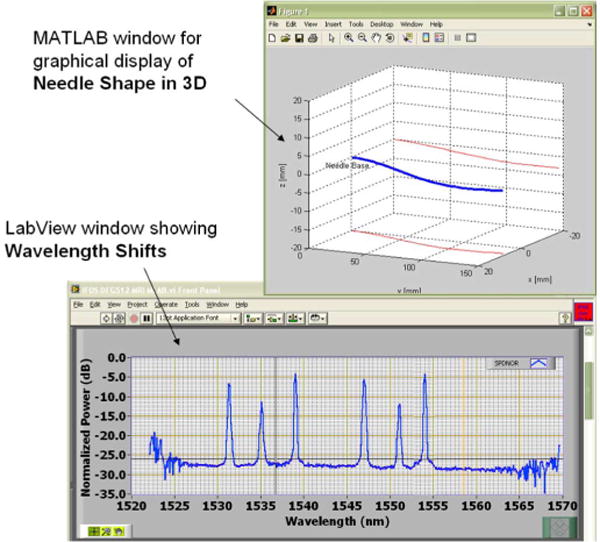
Screen capture of the display of the real-time monitoring system.
Magnetic susceptibility and safety are the concerns involving surgical tools and devices used in the MRI field [36]. Consequently, the interrogator and laptop computer were located remote from the MRI machine. The fiberoptic cables are non-metallic and do not interfere with the MRI magnetic field or machinery.
VII. Preliminary MRI Scanner Tests
The FBG needle prototype, which can potentially be used with various interventional MR-guided procedures, was tested for MRI compatibility in order to prove:
no imaging artifacts are caused by the sensors;
the sensor signals are not affected by the MRI scanner.
The modified needle presented the same degree of artifact as an unmodified needle. The dark artifact that can be seen at the trocar tip [see Figs. 7 and 8(a)], is due to the intersection of the different materials present in the outer sheath and inner stylet; it is equally seen in this imaging plane with the unmodified needle.
Fig. 7.
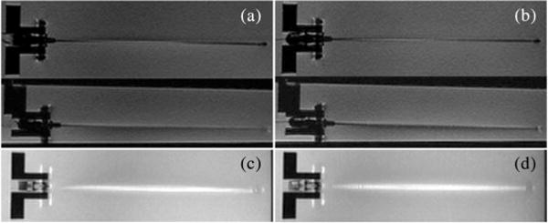
RTFSE images of the biopsy needle with and without optical fibers and FBGs show the same degree of needle artifact. (a) Unmodified needle, coronal and sagittal view. (b) Modified needle, coronal and sagittal view. Maximum intensity projections (MIP) through a 3-D volume of acquired images show the cumulative bright artifact caused by the needle. The amount of artifact between the two needles is comparable. (c) MIP of the unmodified needle. (d) MIP of the modified needle.
Fig. 8.
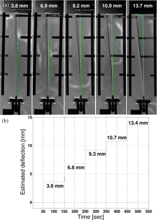
(a) MRI-scanned images with different deflections. The deflection relative to MR images were found using a measurement tool in OsiriX [35] software for viewing medical DICOM images. (b) Estimated needle deflections using FBG sensors.
To show that no significant imaging artifact is produced by the FBG sensors and optical fibers, MR images of the needle prototype and an unmodified needle in a water bath were compared. During image-guided procedures, a real-time pulse sequence, such as the Real-time Fast Spin Echo (RTFSE) would be used. Real-time coronal and sagittal images (TE = 37.856 ms, TR = 1969 ms, thickness = 3 mm), with a 24-cm field of view (FOV) in the frequency direction along the needle, are shown in Fig. 7(a) and (b). To directly compare image artifact, a higher resolution, 3-DFSE sequence (TE = 18.752 ms, TR = 1500 ms, thickness = 0.8 mm) was used. With DICOM viewer software, OsiriX (Genève, Switzerland) [35], a maximum intensity projection (MIP) of the full volume of 3-DFSE images (total thickness = 10.40 mm) was made in the coronal and sagittal views. The coronal MIPs are shown in Fig. 7(c) and (d). Using the measurement tool in OsiriX, the width across the thickest region of the bright artifact was measured every centimeter along the needle three times and averaged. The width of the artifact differed by 0.02% between the modified and unmodified needle in the coronal views and by 0.14% in the sagittal views.
The second objective can be reached by comparing the estimated deflections acquired by the sensor signals and the deflections measured in the MR images. The needle was placed in a water bath and deflected with Nylon screws in five different loading configurations, as shown in Fig. 8. Results show the estimated tip deflections are comparable to the deflections measured in the MR images. Autonomous control of the scan plane is beyond the scope of this paper; however, as can be seen in Fig. 8(a), in order to show the entire needle profile, the imaging plane has been adjusted.
VIII. Conclusion and Future Work
We developed an MRI-compatible biopsy needle, and instrumented it with optical FBGs for measuring bending deflections of the needle as it is inserted into tissues. During interventional procedures, such as diagnostic biopsies and localized treatments, it is useful to track any tool deviation from the planned trajectory to minimize positioning error and procedural complications. The goal is to display tool deflections in real time, with greater bandwidth and accuracy than when viewing the tool in MR images. A standard 18 ga × 15 cm inner needle was prepared with embedded optical fibers. Two sets of sensors, located at different points along the needle, provide a measurement of the tip deflection, and an estimate of the bent profile, as well as providing temperature compensation. Tests of the needle in a water bath showed that it produced no adverse imaging artifacts when used with the MR scanner and no sensor signal degradation from the strong magnetic field.
The main sources of error in the prototype can be attributed to imperfect placement of the FBGs in the needle and to the use of just two sets of sensors along the needle’s length. With three or more sensor locations, the accuracy of the estimated profile will improve, particularly if the needle is calibrated to account for errors in FBG placement. Ultimately, a more repeatable manufacturing process may make such calibration unnecessary. Other immediate improvements will include a faster interrogator so that the needle can be monitored at rates of 100 Hz or higher.
The field of minimally invasive medical procedures represents a new application area for FBG sensors, albeit with significant design and manufacturing challenges. Foremost among these is the need to minimize sensor package size and to integrate sensors directly with surgical and diagnostic tooling. Given that fiberoptic devices are inherently MRI-compatible, do not interact with the MRI process, and do not cause significant imaging artifacts, they provide an ideal method of sensing the configuration and forces upon interventional devices in the MRI environment. We plan to further test this approach in MR environments and to develop an Application programming interface (API) to overlay the real-time deflection results on MR images. Interventional radiologists can subsequently use the deflection information to interactively change the image scanning plane.
Currently, the low quantity cost of a single FBG in a standard 125-μm silica fiber with 250-μm-diameter acrylate coating costs about $50. An array of ten FBGs on a single fiber costs around $900. Smaller 80-μm fibers are slightly more expensive. In mass quantities, the price drops significantly. Overall, these costs are small in comparison to most disposable devices for interventional and percutaneous procedures. Furthermore, the price of FBGs is expected to drop in the next five years, making the integration of FBGs into a disposable product such as ours financially plausible. The shape-sensing stylet would be onetime sterilizable, possible by gamma, e-beam, X-ray, or similar method, which will not harm the biocompatible adhesive, FBGs, optical fibers, or plastic connectors. The electronics will be a capital purchase, and draped or kept outside the MR suite during procedures.
Applications for FBGs and microscale fiber optics include incorporation into existing MRI-compatible robots and equipment for needle or probe positioning [5], [8], [13], [23], [24], [27]. Any needle-driving robot will experience the same deflections that physicians encounter. FBG-sensorized needles and probes can be used to help plan the trajectories of these robots [4] to compensate for common deflections in various tissues, as well as measure contact tissue forces. The modified stylet can also be used as a force gauge to validate tissue deformation models in vivo for surgical computer-aided design/computer-aided manufacturing (CAD/CAM) procedures [21].
Acknowledgments
This work was supported in part by the U.S. Army Medical Research Acquisition Activity (USAMRAA) through Small Business Technology Transfer (STTR) under Contract W81XWH8175M677, in part by the National Institutes of Health (NIH) through “Techniques for MRI-Guided Cryosurgery of Prostate Cancer” under Contract RO1 CA/DK092061, and in part by the Graduate Research Fellowship Program (GRFP) of the National Science Foundation (NSF).
Biographies

Yong-Lae Park (M’10) received the B.S. degree in industrial engineering from Korea University, Seoul, Korea, in 2000, and the M.S. and the Ph.D. degrees in mechanical engineering from Stanford University, Stanford, CA, in 2005 and 2010, respectively.
He is currently a Technology Development Fellow at the Wyss Institute for Biologically Inspired Engineering, Harvard University, Boston, MA. His research interests include fiber-optic force and tactile sensing of robot manipulators for space and medical applications, design of haptic systems for minimally invasive surgery robots, 3-D smart-robot-structure development, and development of wearable robotic devices for rehabilitation.

Santhi Elayaperumal (S’08) received the B.S. degree in biomedical engineering in 2006 from the University of Minnesota, Twin Cities, and the M.S. degree in mechanical engineering in 2009 from Stanford University, Stanford, CA, where she is currently working the Ph.D. degree in mechanical engineering.
Her research interests include fiber-optic force sensing and haptics for medical applications, integrative systems for surgical robotics, and design methodologies for high-technology projects.

Bruce Daniel received the B.A. degree from Williams College, Williamstowm, MA, in 1985, and the M.D. degree from Harvard Medical School, Boston, MA, in 1990.
He is currently an Associate Professor and Physician in the Department of Radiology, Stanford University, Stanford, CA. His research interests include cost analysis of breast cancer screening, MRI-directed sonic ablation for prostate cancer, techniques for MRI-guided cryosurgery, and iMRI methods for cancer diagnosis and treatment.

Seok Chang Ryu received the B.S. degree in mechanical engineering from Pohang University of Science and Technology (POSTECH), Pohang, Korea, in 2002, and the M.S. degree in mechanical engineering, in 2007 from Stanford University, Stanford, CA, where he is currently working toward the Ph.D. degree in mechanical engineering.
He was involved in research on the development of trajectory planners for selective compliant assembly robot arm (SCARA) robots and wafer-transfer robots at Robostar Company Ltd., Seoul, Korea. His research interests include medical applications of robots.
Mihye Shin received the B.S. degree in mechanical engineering in 2008 from Korea Advanced Institute of Science and Technology (KAIST), Daejeon, Korea, and the M.S. degree in mechanical engineering in 2010 from Stanford University, Stanford, CA, where she is currently working toward the Ph.D. degree in mechanical engineering.
Her current research interests include design of electrical/mechanical systems for medical applications, surgery robots, and rehabilitation systems.
Joan Savall (M’03) received the Ph.D. degree in mechanical engineering from the University of Navarra, Spain, in 2005.
He is currently a Senior Scientist at the Howard Hughes Medical Institute (HHMI), Chevy Chase, MD, and a Consulting Assistant Professor in the Mechanical Engineering Department, Design Division, Stanford University, Stanford, CA. His research interests include mechanical design, haptics, robotics, and mechatronics. He is involved in research on the design of new haptic devices for virtual reality, and special robotic devices for medical applications and bioscience research.

Richard J. Black (M’84–SM’09) received the B.Sc. (Hons.) degree in physics from the University of Canterbury, Canterbury, New Zealand, and the Ph.D. degree in fiber optics from the Research School of Physical Sciences, Australian National University, Canberra, Australia.
He is currently a Founding Member and the Chief Scientist at Intelligent Fiber Optic Systems Corporation, Santa Clara, CA. He is the Founder of OptoSapiens Design. His research interests include optical-fiber sensing systems with application to structural health monitoring, robotics, and medical devices.
Dr. Black is a member of the Association for Advancement of Artificial Intelligence, the Optical Society of America, the Materials Information Society, the International Society for Optical Engineers, and the Society for the Advancement of Material and Process Engineering.

Behzad Moslehi (M’84–SM’98) received the B.S. degree in electrical engineering, in 1978, from AryaMehr University of Technology, Tehran, Iran, and the M.S. degree in electrical engineering, in 1980, the M.S. degree in applied physics, in 1984, and the Ph.D. degree in electrical engineering, in 1984, from Stanford University, Stanford, CA.
He is the Founder and Chief Executive Officer/Chief Technology Officer of Intelligent Fiber Optic Systems Corporation, Santa Clara, CA. His current research interests include photonic signal processing, sensing, communications, and networking for applications in avionics, safety, life sciences, and energy.
Dr. Moslehi is a Senior Member of the Optical Society of America, the International Society for Optical Engineers, the Society for the Advancement of Material and Process Engineering, the Society of Petroleum Engineers, the American Wind Energy Association, and Sigma Xi.

Mark R. Cutkosky (M’93) received the Ph.D. degree in mechanical engineering from Carnegie Mellon University, Pittsburgh, PA, in 1985.
He is currently a Professor of mechanical engineering at Stanford University, Stanford, CA. His current research interests include robotic manipulation and tactile sensing, and the design and fabrication of biologically inspired robots.
Prof. Cutkosky is a recipient of a Fulbright Faculty Chair, the Charles M. Pigott Professorship, and the National Science Foundation Presidential Young Investigator Award. He is a member of the American Society of Mechanical Engineers and Sigma Xi.
Footnotes
Recommended by Guest Editor K. Masamune.
Contributor Information
Yong-Lae Park, Email: ylpark@wyss.harvard.edu, Wyss Institute for Biologically Inspired Engineering, Harvard University, Boston, MA 02115, USA.
Santhi Elayaperumal, Email: santhie@stanford.edu, Center for Design Research, Department of Mechanical Engineering, Stanford University, Stanford, CA 94305, USA.
Bruce Daniel, Email: bdaniel@stanford.edu, Department of Radiology, Stanford University, Stanford, CA 94305, USA.
Seok Chang Ryu, Email: scryu@stanford.edu, Center for Design Research, Department of Mechanical Engineering, Stanford University, Stanford, CA 94305, USA.
Mihye Shin, Email: mhshin@stanford.edu, Center for Design Research, Department of Mechanical Engineering, Stanford University, Stanford, CA 94305, USA.
Joan Savall, Email: jsavall@stanford.edu, Howard Hughes Medical Institute, Chevy Chase, MD 20815 USA, and also with the Center for Design Research, Department of Mechanical Engineering, Stanford University, Stanford, CA 94305, USA.
Richard J. Black, Email: rjb@ifos.com, Intelligent Fiber Optic Systems (IFOS) Corporation, Santa Clara, CA 95054, USA.
Behzad Moslehi, Email: bm@ifos.com, Intelligent Fiber Optic Systems (IFOS) Corporation, Santa Clara, CA 95054, USA.
Mark R. Cutkosky, Email: cutkosky@stanford.edu, Center for Design Research, Department of Mechanical Engineering, Stanford University, Stanford, CA 94305, USA.
References
- 1.Abolhassani N, Patel R, Moallem M. Needle insertion into soft tissue: A survey. Med Eng Phys. 2007;29(4):413–431. doi: 10.1016/j.medengphy.2006.07.003. [DOI] [PubMed] [Google Scholar]
- 2.Blumenfeld P, Hata N, DiMaio S, Zou K, Haker S, Fichtinger G, Tempany C. Transperineal prostate biopsy under magnetic resonance image guidance: A needle placement accuracy study. J Magnet Reson Imag. 2007;26:688–694. doi: 10.1002/jmri.21067. [DOI] [PubMed] [Google Scholar]
- 3.Bradski GR, Kaehler A. Learning OpenCV. 1. Sebastopol, CA: O’Reilly; 2008. [Google Scholar]
- 4.Cepolina F, Michelini RC. Robots in medicine: a survey of in-body nursing aids introductory overview and concept design hints; presented at the 35th Int. Symp. Robot., ISR; 2004; Paris, France. [Google Scholar]
- 5.Chinzei K, Miller K. Towards MRI guided surgical manipulator. Med Sci Monit, Int Med J Exp Clin Res. 2001;7(1):153–163. [PubMed] [Google Scholar]
- 6.Derbyshire JA, Hinks RS, Graham AW, Henkelman RM. Dynamic scan plane tracking using MR position monitoringsource. 5 947 900. US Patent. 1998 Apr 13; doi: 10.1002/jmri.1880080423. [DOI] [PubMed]
- 7.Dimaio S, Samset E, Fischer G, Iordachita I, Fichtinger G, Jolesz F, Tempany C. Dynamic MRI scan plane control for passive tracking of instruments and devices. Proc Med Image Comput Comput Assist Intervention (MICCAI 2007) 10(Pt2):50–58. doi: 10.1007/978-3-540-75759-7_7. [DOI] [PubMed] [Google Scholar]
- 8.Dimaio SP, Fischer GS, Maker SJ, Hata N, Iordachita I, Tempany CM, Kikinis R, Fichtinger G. A system for MRI-guided prostate interventions. Proc 1st IEEE/RAS-EMBS Int Conf Biomed Robot Biomech (BioRob2006) 2006:68–73. [Google Scholar]
- 9.DiMaio SP, Pieper S, Chinzei K, Hata N, Balogh E, Fichtinger G, Tempany CM, Kikinis R. Interactive simulation of needle insertion models. IEEE Trans Biomed Eng. 2005 Jul;52(7):1167–1179. doi: 10.1109/TBME.2005.847548. [DOI] [PubMed] [Google Scholar]
- 10.DiMaio SP, Salcudean SE. Needle insertion modeling and simulation. IEEE Trans Robot Autom. 2003 Oct;19(5):864–875. [Google Scholar]
- 11.Dumoulin CL, Souza SP, Darrow RD. Real-time position monitoring of invasive devices using magnetic resonance. Magn Reson Med. 1993;29(3):411–415. doi: 10.1002/mrm.1910290322. [DOI] [PubMed] [Google Scholar]
- 12.Leo G, Aeby N. A fiber optic force sensing catheter. WO 2010 079418. International Patent. 2010 Jul 15;
- 13.Fischer GS, Iordachita I, Csoma C, Tokuda J, Dimaio SP, Tempany CM, Hata N, Fichtinger G. Mri-compatible pneumatic robot for transperineal prostate needle placement. IEEE/ASME Trans Mechatronics. 2008 Jun;13(3):295–305. doi: 10.1109/TMECH.2008.924044. [DOI] [PMC free article] [PubMed] [Google Scholar]
- 14.Gere JM, Goodno BJ. Mechanics of Materials. 7. Lubbock, TX: CL-Engineering; Apr, 2008. [Google Scholar]
- 15.Hill KO, Meltz G. Fiber Bragg grating technology fundamentals and overview. J Lightw Technol. 1997;15(8):1263–1276. [Google Scholar]
- 16.Hochman MN, Friedman MJ. In vitro study of needle deflection: A linear insertion technique versus a bidirectional rotation insertion technique. Quintessence Int. 2000;31(1):33–39. [PubMed] [Google Scholar]
- 17.Hollerbach JM, Wampler CW. The calibration index and taxonomy for robot kinematic calibration methods. Int J Robot Res. 1996 Dec;15(6):573–591. [Google Scholar]
- 18.Hushek SG, Fetics B, Moser RM, Hoerter NF, Russel LJ, Roth A, Polenur D, Nevo E. Initial clinical experience with a passive electromagnetic 3D locator system. Proc 5th Intervent MRI Symp. 2004:73–74. [Google Scholar]
- 19.Iordachita I, Sun Z, Balicki M. A sub-millimetric, 0.25 mN resolution fully integrated fiber-optic force-sensing tool for retinal microsurgery. Int J Comput Assist Radiol Surg. 2009;4(4):383–390. doi: 10.1007/s11548-009-0301-6. [DOI] [PMC free article] [PubMed] [Google Scholar]
- 20.Kataoka H, Washio T, Audette M, Mizuhara K. A model for relations between needle deflection, force, and thickness on needle penetration. Proc 4th Int Conf Med Image Comput Comput-Assist Intervent. 2001:966–974. [Google Scholar]
- 21.Kazanzides P, Fichtinger G, Hager GD, Okamura AM, Whitcomb LL, Taylor RH. Surgical and interventional robotics—Core concepts, technology, and design [Tutorial] IEEE Robot Autom Mag. 2008 Jun;15(2):122–130. doi: 10.1109/MRA.2008.926390. [DOI] [PMC free article] [PubMed] [Google Scholar]
- 22.Kochavi E, Goldsher D, Azhari H. Method for rapid MRI needle tracking. Magn Reson Med. 2004;51(5):1083–1087. doi: 10.1002/mrm.20065. [DOI] [PubMed] [Google Scholar]
- 23.Krieger A, Metzger G, Fichtinger G, Atalar E, Whitcomb LL. A hybrid method for 6-dof tracking of MRI-compatible robotic interventional devices. Proc IEEE Int Conf Robot Autom, ICRA. 2006:3844–3849. [Google Scholar]
- 24.Krieger A, Susil RC, Menard C, Coleman JA, Fichtinger G, Atalar E, Whitcomb LL. Design of a novel MRI compatible manipulator for image guided prostate interventions. IEEE Trans Biomed Eng. 2005 Feb;52(2):306–313. doi: 10.1109/TBME.2004.840497. [DOI] [PMC free article] [PubMed] [Google Scholar]
- 25.Lawson CL, Hanson RJ. Solving Least Squares Problems. Englewood Cliffs, NJ: Prentice-Hall; 1974. [Google Scholar]
- 26.Leung DA, Debatin JF, Wildermuth S, Mckinnon GC, Holtz D, Dumoulin CL, Darrow RD, Hofmann E, von Schulthess GK. Intravascular MR tracking catheter: Preliminary experimental evaluation. Amer J Roentgenol. 1995 May;164(5):1265–1270. doi: 10.2214/ajr.164.5.7717244. [DOI] [PubMed] [Google Scholar]
- 27.Muntener M, Patriciu A, Petrisor D, Schar M, Ursu D, Song DY, Stoianovici D. Transperineal prostate intervention: Robot for fully automated MR imaging—System description and proof of principle in a canine model. Radiology. 2008 May;247(2):543–549. doi: 10.1148/radiol.2472070737. [DOI] [PMC free article] [PubMed] [Google Scholar]
- 28.Naganawa S, Ishiguchi T, Ishigaki T, Sato K, Katagiri T, Kishimoto H, Mimura T, Takizawa O, Imura C. Real-time interactive mr imaging system: Sequence optimization, and basic and clinical evaluations. Radiat Med. 2000;18(1):71–79. [PubMed] [Google Scholar]
- 29.Othonos A, Kalli K. Fiber Bragg Gratings: Fundamentals and Applications in Telecommunications and Sensing. Boston, MA: Artech House; 1999. [Google Scholar]
- 30.Park Y-L, Chau K, Black RJ, Cutkosky MR. Force sensing robot fingers using embedded fiber Bragg grating sensors and shape deposition manufacturing. Proc 2007 IEEE Int Conf Robot Autom. :1510–1516. [Google Scholar]
- 31.Park Y-L, Elayaperumal S, Daniel BL, Kaye E, Pauly KB, Black RJ, Cutkosky MR. MRI-compatible haptics: Feasibility of using optical fiber Bragg grating strain-sensors to detect deflection of needles in an MRI environment; presented at the 16th Sci. Meet Exhibition Int. Soc. Magn. Reson. Med. (ISMRM); 2008; Toronto, ON, Canada. [Google Scholar]
- 32.Park Y-L, Elayaperumal S, Ryu S, Daniel BL, Black RJ, Moslehi B, Cutkosky MR. MRI-compatible haptics: Strain sensing for realtime estimation of three dimensional needle deflection in MRI environments; presented at the 17th Sci. Meet. Exhibition Int. Soc. Magn. Reson. Med. (ISMRM); 2009; Honolulu, HI. [Google Scholar]
- 33.Park Y-L, Ryu SC, Black RJ, Chau KK, Moslehi B, Cutkosky MR. Exoskeletal force-sensing end-effectors with embedded optical fiber-Bragg-grating sensors. IEEE Trans Robot. 2009 Dec;25(6):1319–1331. [Google Scholar]
- 34.Park Y-L, Ryu SC, Black RJ, Moslehi B, Cutkosky MR. Fingertip force control with embedded fiber Bragg grating sensors. Proc 2008 IEEE Int Conf Robot Autom. 2008:3431–3436. [Google Scholar]
- 35.Rosset A, Heuberger J. OsiriX Imaging Software: Advanced Open-Source PACS Workstation DICOM Viewer [Online] Available: http://www.osirix-viewer.com.
- 36.Schenck JF. The role of magnetic susceptibility in magnetic resonance imaging: MRI magnetic compatibility of the first and second kinds. Med Phys. 1996;23(6):815–850. doi: 10.1118/1.597854. [DOI] [PubMed] [Google Scholar]
- 37.Silverman SG, Collick BD, Figueira MR, Khorasani R, Adams DF, Newman RW, Topulos GP, Jolesz FA. Interactive MR-guided biopsy in an open-configuration MR imaging system. Radiology. 1995 Oct;197(1):175–181. doi: 10.1148/radiology.197.1.7568819. [DOI] [PubMed] [Google Scholar]
- 38.Sun Z, Balicki M, Kang J, Handa J, Taylor R, Iordachita I. Development and preliminary data of novel integrated optical micro-force sensing tools for retinal microsurgery. Proc 2009 IEEE Int Conf Robot Autom. 2009:1897–1902. [Google Scholar]
- 39.Timoshenko S, Young DH. Engineering Mechanics. 4. New York: McGraw-Hill; 1956. [Google Scholar]
- 40.Utzinger U, Rebecca RR-K. Fiber optic probes for biomedical optical spectroscopy. J Biomed Opt. 2003;8(1):121–147. doi: 10.1117/1.1528207. [DOI] [PubMed] [Google Scholar]
- 41.Wan G, Wei Z, Gardi L, Downey DB, Fenster A. Brachytherapy needle deflection evaluation and correction. Med Phys. 2005;32(4):902–909. doi: 10.1118/1.1871372. [DOI] [PubMed] [Google Scholar]
- 42.Werner R, Krueger S, Winkel A, Albrecht C, Schaeffter T, Heller M, Christian F. MR-guided breast biopsy using an active marker: A phantom study. J Magn Reson Imag. 2006;23:235–241. doi: 10.1002/jmri.20600. [DOI] [PubMed] [Google Scholar]
- 43.Zhang L, Qian J, Zhang Y, Shen L. On SDM/WDM FBG sensor net for shape detection of endoscope. Proc 2005 IEEE Int Conf Robot Autom. 4:1986–1991. [Google Scholar]