Abstract
Retinal surgery is one of the most technically challenging surgical disciplines. Many robotic systems have been developed to enhance the surgical capabilities. However, very few of them provide the surgeon the dexterity within the patient’s eye to enable more flexible, more advanced surgical procedures. This paper presents a sub-millimeter intraocular dexterous robot, the Integrated Robotic Intraocular Snake (IRIS). The variable neutral-line mechanism is used to provide very high dexterity with a very small form factor. The IRIS distal dexterous unit is 0.9 mm in diameter and about 3 mm in length. It enables two rotational degrees of freedom at the distal end of the ophthalmic instruments. The analysis on contact mechanics provides a reference for the adjustment of the wire pretension. Redundant actuation is implemented by using one motor for each wire. A motion scaling transmission is developed to overcome the suboptimal resolution of the motors. A scale-up model of the IRIS is built for initial experimental evaluation. Preliminary results show that the scale-up IRIS can provide large range of motion. For given bending angle, the kinematic model can estimate the desired wire translation when the friction is not significant. The first prototype of the actual-scale IRIS is assembled and tested.
I. INTRODUCTION
Retinal microsurgery refers to a family of microsurgical procedures that treat retinal diseases such as retina detachment, macular degeneration, diabetic retinopathy, epiretinal membrane, and retinal vein occlusion. Retinal microsurgery is one of the most technically challenging and high-consequence surgical disciplines. In the operating room, a surgical microscope is positioned above the patient’s eye to provide magnified visualization of the posterior of the eye, as shown in Fig. 1. Small instruments, e.g., 23 Ga with 0.65 mm diameter, are inserted through trocars on the sclera to operate at the back of the eye. The surgeon needs to control the instrument motion in a very fine and precise manner to handle the delicate eye tissue. Due to the trocar constraint at the sclerotomy, the instrument motion is coupled with the eye movement. If the surgeon intends to keep the patient’s eye still, only three rotational degrees of freedom (DOF) about the sclerotomy and one translational DOF along the instrument axis are allowed. This concept is termed as remote center-of-motion (RCM) in robotics, devised by Taylor et al. [1]. The lateral translation of the tool will move the patient’s eye, causing change of the view in the microscope and possibly relative motion between the instrument and the retina, which is potentially risky when the instrument tip is close to the retina. This constraint limits not only the instrument workspace inside the patient’s eye, but also the orientation of the instrument at a given position. Similar problem exists in laparoscopic surgery. Robotic systems have demonstrated significant dexterity enhancement by integrating additional DOFs at the distal end of the surgical instruments [2], e.g., the EndoWrist instruments from Intuitive Surgical.
Fig. 1.
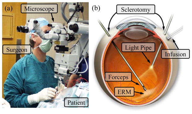
Retinal microsurgery: (a) position of the patient and the lead surgeon in the operating room. (b) the layout of the surgical instruments in the eye during ERM peeling. A straight forceps tool is used to perform ERM peeling.
In retinal microsurgery, instrument dexterity at the distal end can potentially be very useful. One example procedure is epiretinal membrane (ERM) peeling. ERM is a thin, semi-transparent layer of scar tissue that forms on top of the retina. It causes stress on the retina, and wrinkling of the retinal surface, thus distorts the patient’s vision. In ERM peeling, the surgeon typically uses a micro-forceps tool to carefully grasp the edge of the membrane, and slowly delaminates it off the retina, as shown in Fig. 1. Besides straight instruments, angled instruments are available to enable approaching the membrane with different tool orientations, e.g., 45° delamination spatula and pic, as well as vertical 90° scissors. Incorporating additional DOFs at the distal end of the instrument, can provide more flexibility for the surgeon to grasp the membrane with the optimum angle, and to control the peeling trajectory with minimum shear stress on the retina [3]. Another difficult procedure is retinal vein cannulation (RVC) that treats retinal vein occlusion. Therapeutic agent, e.g., plasminogen activator (t-PA), is directly injected into the occluded vein using a micropipette. Retinal veins are typically less than 100 μm in diameter. The micropipette needs to puncture the retinal vein, and to stay within the vessel for drug delivery. Fig. 2 illustrates a simulated RVC, in which a 70 μm micropipette is used to inject air into the vessel of a chorioallantoic membrane. Using an angled micropipette, e.g., 30° [4], or aiming a straight micropipette at the vessel with an angle, e.g., 45° [5], can enable a more gradual approach to the retina vein, and potentially improve safety by reducing the likelihood of puncturing through the retina vein. These surgical instruments with angled tip provide a suboptimal solution with increased number of instruments and cumbersome surgical workflow.
Fig. 2.
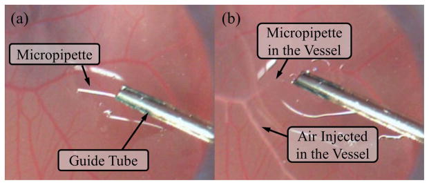
Retinal vein cannulation simulated using a chorioallantoic membrane (CAM): (a) the micropipette (ø70 μm) is deployed from a guide tube that is positioned with about 45° from the CAM surface. (b) The micropipette is punctured into the vessel and injects air to visualize the successful cannulation.
A number of robotic systems for retinal microsurgery have been developed to enhance the natural human capabilities. The main approaches are hands-on cooperatively controlled systems [6]–[10], mater-slave teleoperated systems [11]–[18], handheld robotic devices [19], [20], and untethered micro-robots [21]. The untethered micro-robots have the least constraints on workspace and manipulability, can overcome many current limitations if they can deliver sufficient force and the surgical workflow can be adapted accordingly. Wei et al. investigated the approach with pre-curved concentric nitinol tubes to provide intraocular dexterity [22], [23]. Microstent delivery into the retinal vessel was attempted. The maximum curvature to pre-bend a nitinol tube poses the challenge on balancing the length of the dexterous wrist mechanism and the range of motion, i.e., maximum rotation angle.
In this paper, we present the IRIS: Integrated Robotic Intraocular Snake, a sub-millimeter robotic distal dexterous unit that provides 2-DOF rotation at the tip of an ophthalmic instrument. The design of the IRIS distal dexterous unit, the actuation unit, and preliminary experimental results will be described in the following sections.
II. DESIGN
A. Design Requirements
Retinal microsurgery poses many strict constraints on the system design. Table I summarizes the design specifications. The IRIS needs to be compact, while providing sufficient DOFs and range of motion. The desired outer diameter of the IRIS is 0.9 mm, consistent with 20 Ga ophthalmic instruments. The length of the IRIS is desired to be as short as possible, not exceeding 10 mm, because the IRIS needs to provide large rotation within small space, reducing the possibility of collision with surrounding tissue and other tools. Two rotational DOFs with ±45° range of motion with each DOF can provide fairly good flexibility as the first design iteration. To experiment with potential clinical procedures, e.g., ERM peeling and RVC, the IRIS also needs to be able to deliver sufficient force. The desired payload is set to be 30 mN, considering that the forces exerted are mostly below 15 mN in both ERM peeling [24] and RVC [5], [25]. It is also desirable to have a hollow lumen in the center that can be used as a working channel, e.g., for micro-forceps actuation. In addition, the IRIS system should be able to be integrated with the Steady-Hand Eye Robot [7]–[9], to enhance the macro Cartesian motion.
TABLE I.
Design Specifications of the IRIS System
| Dimension | Diameter | ≤ 0.9 mm |
| Length | ≤ 10 mm | |
|
| ||
| Performance | Degree of freedom | 2-DOF rotation |
| Range of motion | each DOF ±45° | |
| Payload | 30 mN | |
|
| ||
| Additional requirements | Inner lumen: as a working channel | |
| Compatiblity: can be incorperated with the Steady-Hand Eye Robot | ||
B. IRIS Distal Dexterous Unit
Due to the strict dimension requirements, it is difficult to incorporate standard revolute joints [26] at the distal end of the ophthalmic tools. Instead, snake-like mechanisms are more suitable for enabling bending/rotation with a small form factor. Previously, many snake-like robots have been developed for minimally invasive surgery and other interventional procedures. Degani et al. developed a highly articulated robot using cylindrical links to form spherical joints [27]. Simaan [28] devised a flexible backbone snake manipulator with wire actuation, which later evolved into a multi-arm, single port access surgical system [29]. Flexure-based snake-like robots [30]–[32] can provide sufficient structural strength and range of motion with large diameter, yet can be difficult to implement on a sub-millimeter scale level. Swaney et al. investigated miniature flexures based on nitinol wires [33], [34]. However, it is not feasible to preserve an inner lumen as a working channel. Novel concepts, such as interlocking fibers [35], layer [36] and granular [37], [38] jamming, as well as pneumatically driven flexible manipulator [39], are difficult to miniaturize down below a millimeter, due to manufacturing limitations. Kim et al. [40] proposed a novel variable neutral-line mechanism, which can provide large bending with a compact structure, requires fairly straight forward manufacturing, and is possible to scale down to a sub-millimeter level.
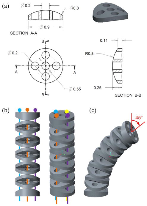
The IRIS distal dexterous unit adapts the principle of the variable neutral-line mechanism. The basic building blocks are identical disc-like elements, as shown in Fig. 3(a). Instead of flat, the top and bottom surfaces of each element are curved, i.e., cylindrical surfaces. The axis of the top cylindrical surface is orthogonal to that of the bottom cylindrical surface. By assembling the elements alternately in orthogonal directions, the contact surfaces between the adjacent elements form rolling joints, as shown in Fig. 3(b). The center hole is 200 μm in diameter, can be used to carry a micropipette, or to pass a wire for the micro-forceps actuation. The other four holes around the center hole are used for the actuation wires of the snake-like mechanism. Fig. 3(c) illustrates the IRIS in a 45° bending position. Each disc-like element is 0.9 mm in diameter, and 0.25 mm in height. All the holes are 0.2 mm in diameter. The radius of the cylindrical surfaces is 0.8 mm. Nitinol wires with a diameter of 0.125 mm are used for actuation. All the disc-like elements are made of brass, micro-machined with precision CNC (BeiSi Technology, Shenzhen, China). Detailed analysis on the mechanics and kinematics of the variable neutral-line mechanism can be found in [40], thus is not repeated in this paper. The contact mechanics within the IRIS is described below.
Fig. 3.
IRIS distal dexterous unit design: (a) technical drawing of the element with detailed dimensions. (b) IRIS distal dexterous unit assembly in the straight neutral configuration. (c) IRIS is bending 45°. Actuation wires are not shown in (c).
C. Contact Mechanics
Only the pretension in the actuation wires keeps all the disc-like elements together. It is important to determine the proper pretension to apply on the IRIS. Hertz theory [41] is used to determine the maximum pretension. First, we simplify the rolling joint as the contact of two identical cylinder with the radius r = 0:8 mm. The forces exerted by the four wires are modeled as an equivalent force applied in the center, normal to the contact surface. The contact region is a rectangle with a length l = 0:9 mm, and a width of 2b, where b is defined as follows:
| (1) |
where b and l denote the half width and the length of the rectangular contact region, respectively, r denotes the radius of the cylinders, and E denotes the Young’s modulus of brass.
The maximal pressure between the cylinders Pmax can be calculated:
| (2) |
The maximal pressure should not exceed the material yield stress, σ = 97 MPa for brass. F can be calculated by setting Pmax = σ and plugging (1) into (2):
| (3) |
Substituting the variables in, the maximal pretension is determined as 0.8 N. If the pretension is equally distributed among the four wires, each wire should be pretensioned less than 0.2 N.
D. IRIS Actuation Unit
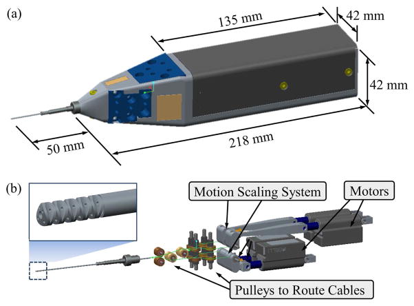
The IRIS actuation unit consists of four motors, motion scaling transmissions, a set of pulley guides to route the wires, and the housing. Fig. 4 illustrates the design of the actuation unit and its housing.
Fig. 4.
IRIS assembly: (a) overall dimension of IRIS system. (b) the components of the actuation unit in the view without the housing.
Although the IRIS only has two DOFs, redundant actuation is implemented for flexibility in control. Four linear motors (L12, Firgelli Technologies, NC, Canada) are used to provide independent actuation of four wires. The travel lengths of the actuation wires for the same bending DOF are not symmetric, i.e., when one wire is retracted to pull the IRIS to bend, the opposite wire needs to release a longer travel to balance the geometric constraint. The low-cost Firgelli motors provide a stroke of 20 mm with a position resolution of 0.1 mm. In order to achieve better accuracy, a motion scaling transmission is used for each wire. The motion scaling is implemented with a lever mechanism. The ratio between the moment arm for motor input and that for wire output is 5:1. However, the linear motion of the motor is translated to the lever rotation through a crank mechanism. Therefore, the motion scaling ratio between the linear motion of the motor and that of the wire is not fixed at 5:1, e.g., when the motor travel reaches 5 mm, the motion scaling ratio can drop to about 4.8:1. This relationship can be easily solved using geometric conditions. The IRIS distal dexterous unit is mounted on the distal end of a 20 Ga stainless steel tube. The four wires exit the proximal end of the stainless steel tube, then slide around a set of pulley guides to connect to the motion scaling transmissions. The wire pretensions can be adjusted using the small screws on the levers.
The design of the IRIS actuation unit is relatively compact. It can be either used as a handheld tool or can be mounted on the Steady-Hand Eye Robot.
III. EXPERIMENTS AND RESULTS
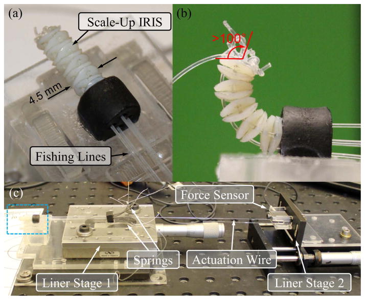
For initial evaluation, a 5:1 scale-up model of the IRIS distal dexterous unit is built using rapid prototyping. The disc-like elements are 3D-printed with an Objet PolyJet printer. The material used is VeroWhite. Instead of nitinol wires, fishing lines are used for actuation. Fig. 5(a) illustrates the scale-up model mounted on the experimental setup. It can bend over 100°, as shown in Fig. 5(b).
Fig. 5.
The scale-up model of the IRIS distal dexterous unit: (a) scale-up model mounted on the experimental setup. (b) scale-up model in a bending position of over 100°. (c) the experimental setup: blue box shows the IRIS mounted on a fixture, as shown in the close-up view in (a). Compression springs are used to apply pretension. The pretension can be adjusted by translating linear stage 1. The actuation wire can be translated by linear stage 2, while the actuation force can be measured by the force sensor mounted on linear stage 2.
The experiment is to determine the relationship between the bending angle of the scale-up IRIS with respect to the wire translation under different pretensions, i.e., 0 N, 1 N, and 2 N. The experimental setup is shown in Fig. 5(c). Compression springs are used to apply pretension to the scale-up IRIS. A micrometer positioning stage, labeled as linear stage 1 in Fig. 5(c) can be used to adjust the pretension. Only one fishing line is used as the actuation wire, while the other three are tensioned with the compression springs. The actuation wire is connected to a second micrometer positioning stage (linear stage 2) through a force sensor. The user can manually control the travel of the actuation wire with linear stage 2. The actuation force can be measured by the force sensor. The bending angle is read directly using a protractor.
Fig. 6 shows the experimental results, together with the theoretical results derived from the kinematics model. When the bending angle is small, e.g., less than 30°, the theoretical and experimental results are fairly consistent. As the pretension increases, more linear translation of the actuation wire is required to achieve the same bending angle. The greater the bending angle is, the longer the extra wire travel needs to be applied. This is likely due to the increased friction and the elastic deformation of the fishing lines. The preliminary experimental results demonstrate that the scale-up IRIS can provide the ability to reach large bending angles, and the kinematics model can predict the required wire translation when the friction is not significant. Empirical model is potentially more useful to provide the more accurate kinematics for large range of motion.
Fig. 6.
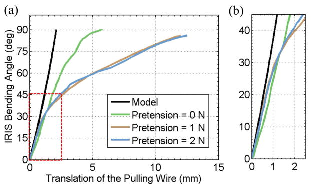
Experimental results with the scale-up model of the IRIS distal dexterous unit: (a) IRIS bending angle vs. the translation of the pulling wire. (b) close-up view of the linear region near the origin, i.e., the region in the red box in (a). Black curve shows the theoretical results obtained using the kinematics model. Green, brown, and blue curves show the experimental results when the pretension is set at 0 N, 1 N, and 2 N, respectively.
IV. THE IRIS ASSEMBLY AND DISCUSSION
A. The IRIS Assembly
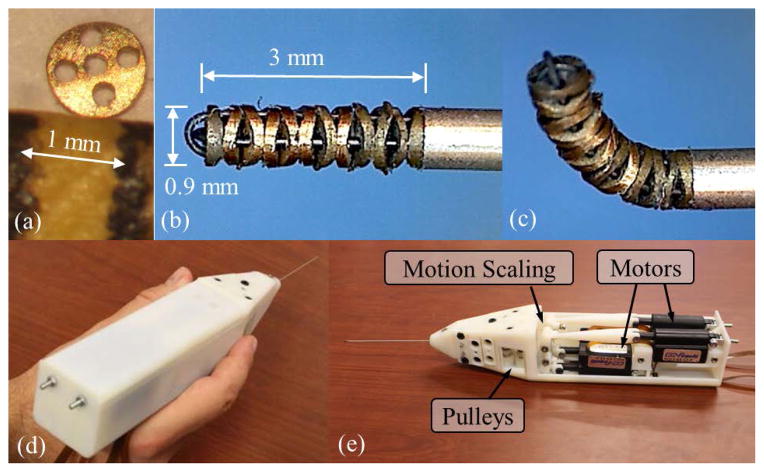
The first actual-size IRIS prototype is assembled, as shown in Fig. 7. Manual assembly requires careful handling of very small parts. Fig. 7(a) shows one disc-like element comparing to 1 mm on a ruler. Threading the 125 μm nitinol wires through several 200 μm holes is challenging. Fig. 7(b) and (c) illustrate the first joint and the fully assembled IRIS distal dexterous unit in neutral position, respectively. It is very compact, with a diameter of 0.9 mm and a length of about 3 mm. The nitinol wires are passed through the stainless steel tube, slided around the pulleys, and fixed on the pretension adjustment screws on the motion scaling transmission. Fig. 7(d) and (e) illustrate the complete assembly and the actuation unit, respectively. A LabView program with graphical user interface is developed to control the IRIS system.
Fig. 7.
IRIS assembly: (a) one disc-like element placed between two marks 1 mm apart on a ruler. (b) the IRIS distal dexterous unit in the neutral position. (c) the IRIS in a bending position close to 90°. (d) a user holding the complete IRIS assembly. (e) IRIS assembly without partial housing, showing the actuation unit.
B. Current Issues
Although this first prototype successfully demonstrates the basic system functionality, there are several issues need to be addressed in the future work. First, higher performance motors need to be used, in order to apply accurate motion control. The current Firgelli motors cannot provide sufficient resolution. The amount of backlash in the motors is significant, hindering the performance of the motion control. Potential candidates are the squiggle motors from New Scale Technologies, or Piezo LEGS from Micromo. Both can provide nanometer resolution with more compact form factor. This can also enable direct drive of the wires, eliminating the motion scaling system and simplifying the actuation unit. Second, the current pretension screw adjustment is difficult to assemble and to modify. Not sufficient space was preserved in the housing for pretension adjustment. Therefore, the pretension calculated in Section II-C is difficult to set properly. In the next iteration, this can be addressed together with the first problem be redesigning the actuation unit.
C. Future Applications
The IRIS system was initially designed to introduce intraocular dexterity into the ophthalmic tools, as shown in Fig. 8(a). This first prototype demonstrates the potential to enhance the surgical capabilities and to enable new procedures that are not possible in current practice. Because the IRIS can provide very high dexterity with a very small form factor, it can also be applied to other interventional procedures, e.g., neuroendoscopy, sinus surgery, intracardiac surgery, and biopsy. Fig. 8(b) illustrates several examples of the potential IRIS applications. For instance, the IRIS can be integrated into the tip of a catheter, enhancing its motion capability. The IRIS can also be incorporated as a needle tip, transforming the regular needle to an actively steerable needle. There is potentially a broad range of applications that can take advantage of this technology.
Fig. 8.
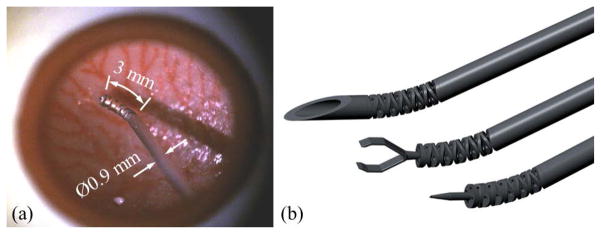
Example applications for the IRIS: (a) IRIS in an eye phantom, (b) potential application as a steerable needle (top), micro-forceps (middle), and micropipette (bottom).
V. CONCLUSIONS
We have presented a sub-millimeter intraocular dexterous robot, i.e., the IRIS. The IRIS distal dexterous unit was designed based on the variable neutral-line mechanism. The analysis on contact mechanics provides a reference for the adjustment of the wire pretension. Redundant actuation is implemented by using one motor for each wire. A motion scaling transmission is developed to overcome the poor resolution of the motors. A scale-up model of the IRIS was developed for initial experimental evaluation. Preliminary results show that the scale-up IRIS can provide large range of motion. For given bending angle, the kinematic model can estimate the desired wire translation when the friction is not significant. The first prototype of the IRIS was assembled. The distal dexterous unit is 0.9 mm in diameter, and about 3 mm in length. With this compact form factor, the IRIS provides two rotational DOFs, and a range of motion of ±90° for each DOF. However, poor motor resolution and suboptimal wire pretension limit the overall performance of the IRIS system. In the future iteration, the actuation unit will be redesigned with miniature, nanometer resolution motors. We will also explore further applications for IRIS, such as an active catheter for intracardiac surgery, steerable needle for biopsy, and so on.
Footnotes
Research supported in part by NIH BRP grant 1 R01 EB 007969, NIH grant R01 EB 000526, and in part by Johns Hopkins University internal funds. Other equipment and systems infrastructure support were developed within the CISST ERC under NSF grant EEC9731748. Dr. Gehlbach is supported by Research to Prevent Blindness, the J. Willard and Alice S. Marriott Foundation, the Gale Trust, and generous gifts by Mr. Herb Ehlers and Mr. Bill Wilbur.
References
- 1.Taylor RH, Funda J, Grossman DD, Karidis JP, LaRose DA. Remote center-of-motion robot for surgery. 5,397,323. US Patent. 1995;14
- 2.Moorthy K, Munz Y, Dosis A, Hernandez J, Martin S, Bello F, Rockall T, Darzi A. Dexterity enhancement with robotic surgery. Surgical Endoscopy. 2004;18(5):790–795. doi: 10.1007/s00464-003-8922-2. [DOI] [PubMed] [Google Scholar]
- 3.Dogramaci M, Williamson TH. Dynamics of epiretinal membrane removal off the retinal surface: a computer simulation project. The British journal of ophthalmology. 2013;97(9):1202–1207. doi: 10.1136/bjophthalmol-2013-303598. [DOI] [PubMed] [Google Scholar]
- 4.Kadonosono K, Arakawa A, Yamane S, Uchio E, Yanagi Y. An experimental study of retinal endovascular surgery with a microfabricated needle. Investigative ophthalmology & visual science. 2011;52(8):5790–5793. doi: 10.1167/iovs.11-7327. [DOI] [PubMed] [Google Scholar]
- 5.Ergeneman O, Pokki J, Pocepcova V, Hall H, Abbott JJ, Nelson BJ. Characterization of puncture forces for retinal vein cannulation. Journal of Medical Devices. 2011;5(4):044504. [Google Scholar]
- 6.Taylor R, Jensen P, Whitcomb L, Barnes A, Kumar R, Stoianovici D, Gupta P, Wang Z, DeJuan E, Kavoussi L. A Steady-Hand Robotic System for Microsurgical Augmentation. The International Journal of Robotics Research. 1999;18(12):1201–1210. [Google Scholar]
- 7.Mitchell B, Koo J, Iordachita I, Kazanzides P, Kapoor A, Handa J, Hager G, Taylor R. Development and application of a new steady-hand manipulator for retinal surgery. IEEE International Conference on Robotics and Automation; 2007. pp. 623–629. [Google Scholar]
- 8.Uneri A, Balicki MA, Handa J, Gehlbach P, Taylor RH, Iordachita I. New Steady-Hand Eye Robot with micro-force sensing for vitreoretinal surgery. IEEE International Conference on Biomedical Robotics and Biomechatronics; 2010. pp. 814–819. [DOI] [PMC free article] [PubMed] [Google Scholar]
- 9.He X, Roppenecker D, Gierlach D, Balicki M, Olds K, Gehlbach P, Handa J, Taylor R, Iordachita I. Toward Clinically Applicable Steady-Hand Eye Robot for Vitreoretinal Surgery. ASME 2012 International Mechanical Engineering Congress and Exposition; 2012. pp. 145–153. [Google Scholar]
- 10.Gijbels A, Wouters N, Stalmans P, Van Brussel H, Reynaerts D, Poorten EV. Design and realisation of a novel robotic manipulator for retinal surgery. IEEE International Conference on Intelligent Robots and Systems; 2013. pp. 3598–3603. [Google Scholar]
- 11.Charles S, Das H, Ohm T, Boswell C, Rodriguez G, Steele R, Istrate D. Dexterity-enhanced telerobotic microsurgery. IEEE International Conference on Advanced Robotics; 1997. pp. 5–10. [Google Scholar]
- 12.Nakano T, Sugita N, Ueta T, Tamaki Y, Mitsuishi M. A parallel robot to assist vitreoretinal surgery. International Journal of Computer Assisted Radiology and Surgery. 2009;4(6):517–526. doi: 10.1007/s11548-009-0374-2. [DOI] [PubMed] [Google Scholar]
- 13.Meenink H. PhD dissertation. Technische Universiteit Eindhoven; 2011. Vitreo-retinal eye surgery robot: sustainable precision. [Google Scholar]
- 14.Ida Y, Sugita N, Ueta T, Tamaki Y, Tanimoto K, Mitsuishi M. Microsurgical robotic system for vitreoretinal surgery. International Journal of Computer Assisted Radiology and Surgery. 2012;7(1):27–34. doi: 10.1007/s11548-011-0602-4. [DOI] [PubMed] [Google Scholar]
- 15.Wei W, Goldman R, Simaan N. Design and theoretical evaluation of micro-surgical manipulators for orbital manipulation and intraocular dexterity. IEEE International Conference on Robotics and Automation; 2007. pp. 10–14. [Google Scholar]
- 16.Yu H, Shen JH, Joos KM, Simaan N. Design, calibration and preliminary testing of a robotic telemanipulator for OCT guided retinal surgery. IEEE International Conference on Robotics and Automation; 2013. pp. 225–231. [Google Scholar]
- 17.Nasseri Ma, Eder M, Nair S, Dean EC, Maier M, Zapp D, Lohmann CP, Knoll A. The introduction of a new robot for assistance in ophthalmic surgery. International Conference of the IEEE Engineering in Medicine and Biology Society; 2013. pp. 5682–5685. [DOI] [PubMed] [Google Scholar]
- 18.Gijbels A, Poorten EBV, Stalmans P, Brussel HV, Reynaerts D. Design of a teleoperated robotic system for retinal surgery. IEEE International Conference on Robotics and Automation; 2014. pp. 2357–2363. [Google Scholar]
- 19.Maclachlan RA, Becker BC, Tabar JC, Podnar GW, Lobes LA, Riviere CN. Micron: an actively stabilized handheld tool for microsurgery. IEEE Transactions on Robotics. 2012;28(1):195–212. doi: 10.1109/TRO.2011.2169634. [DOI] [PMC free article] [PubMed] [Google Scholar]
- 20.Song C, Park DY, Gehlbach PL, Park SJ, Kang JU. Fiber-optic OCT sensor guided”SMART” micro-forceps for microsurgery. Biomedical Optics Express. 2013;4(7):1045–1050. doi: 10.1364/BOE.4.001045. [DOI] [PMC free article] [PubMed] [Google Scholar]
- 21.Kummer MP, Member SS, Abbott JJ, Kratochvil BE, Borer R, Sengul A, Nelson BJ. OctoMag: An Electromagnetic System for 5-DOF Wireless Micromanipulation. IEEE Transactions on Robotics. 2010;26(6):1006–1017. [Google Scholar]
- 22.Wei W, Goldman R, Fine H, Chang S, Simaan N. Performance evaluation for multi-arm manipulation of hollow suspended organs. IEEE Transactions on Robotics. 2009;25(1):147–157. [Google Scholar]
- 23.Wei W, Simaan N. Modeling, force sensing, and control of flexible cannulas for microstent delivery. Journal of Dynamic Systems, Measurement, and Control. 2012;134(4):041004. [Google Scholar]
- 24.Gupta P, Jensen P, de Juan E. Surgical forces and tactile perception during retinal microsurgery. International Conference on Medical Image Computing and Computer Assisted Intervention; 1999. pp. 1218–1225. [Google Scholar]
- 25.Gonenc B, Taylor RH, Iordachita I, Gehlbach P, Handa J. IEEE Sensors. 2014. Force-sensing microneedle for assisted retinal vein cannulation. p. accepted. [DOI] [PMC free article] [PubMed] [Google Scholar]
- 26.Noonan DP, Vitiello V, Shang J, Payne CJ, Yang G-Z. A modular, mechatronic joint design for a flexible access platform for MIS. IEEE/RSJ International Conference on Intelligent Robots and Systems; 2011. pp. 949–954. [Google Scholar]
- 27.Degani A, Choset H, Wolf A, Ota T, Zenati M. Percutaneous intrapericardial interventions using a highly articulated robotic probe. IEEE/RAS-EMBS International Conference on Biomedical Robotics and Biomechatronics; 2006. pp. 7–12. [Google Scholar]
- 28.Simaan N. Snake-like units using flexible backbones and actuation redundancy for enhanced miniaturization. IEEE International Conference on Robotics and Automation; April, 2005; pp. 3012–3017. [Google Scholar]
- 29.Goldman R, Allen P, Fowler D, Simaan N. Design, simulation and evaluation of kinematic alternatives for Insertable Robotic Effectors Platforms in Single Port Access Surgery. IEEE International Conference on Robotics and Automation; 2010. pp. 1053–1058. [Google Scholar]
- 30.Kutzer MD, Segreti SM, Brown CY, Armand M, Taylor RH, Mears SC. Design of a new cable-driven manipulator with a large open lumen: Preliminary applications in the minimally-invasive removal of osteolysis. IEEE International Conference on Robotics and Automation; 2011. pp. 2913–2920. [Google Scholar]
- 31.Qi P, Qiu C, Liu H, Dai JS, Seneviratne L, Althoefer K. A novel continuum-style robot with multilayer compliant modules. IEEE/RSJ International Conference on Intelligent Robots and System; 2014. pp. 3175–3180. [Google Scholar]
- 32.Roppenecker DB, Pfaff A, Coy JA, Lueth TC. Multi arm snake-like robot kinematics. IEEE/RSJ International Conference on Intelligent Robots and Systems; 2013. pp. 5040–5045. [Google Scholar]
- 33.Swaney PJ, Burgner J, Gilbert HB, Webster RJ. A flexure-based steerable needle: high curvature with reduced tissue damage. IEEE Transactions on Biomedical Engineering. 2013;60(4):906–909. doi: 10.1109/TBME.2012.2230001. [DOI] [PMC free article] [PubMed] [Google Scholar]
- 34.Losey DP, York Pa, Swaney PJ, Burgner J, Webster RJ. A flexure-based wrist for needle-sized surgical robots. In: Holmes DR, Yaniv ZR, editors. SPIE Medical Imaging. Vol. 8671. 2013. pp. 86 711G–1. [Google Scholar]
- 35.Moses MS, Kutzer MDM, Armand M. A continuum manipulator made of interlocking fibers. IEEE International Conference on Robotics and Automation; 2013. pp. 4008–4015. [Google Scholar]
- 36.Kim YJ, Cheng S, Kim S, Iagnemma K. A novel layer jamming mechanism with Tunable stiffness capability for minimally invasive surgery. IEEE Transactions on Robotics. 2013;29(4):1031–1042. [Google Scholar]
- 37.Cheng NG, Lobovsky MB, Keating SJ, Setapen AM, Gero KI, Hosoi AE, Iagnemma KD. Design and analysis of a robust, low-cost, highly articulated manipulator enabled by jamming of granular media. IEEE International Conference on Robotics and Automation; 2012. pp. 4328–4333. [Google Scholar]
- 38.Jiang A, Xynogalas G, Dasgupta P, Althoefer K, Nanayakkara T. Design of a variable stiffness flexible manipulator with composite granular jamming and membrane coupling. IEEE/RSJ International Conference on Intelligent Robots and Systems; 2012. pp. 2922–2927. [Google Scholar]
- 39.Cianchetti M, Ranzani T, Gerboni G, De Falco I, Laschi C, Menciassi A. STIFF-FLOP surgical manipulator: mechanical design and experimental characterization of the single module. IEEE/RSJ International Conference on Intelligent Robots and Systems; 2013. pp. 3576–3581. [Google Scholar]
- 40.Kim YJ, Cheng S, Kim S, Iagnemma K. A stiffness-adjustable hyperredundant manipulator using a variable neutral-line mechanism for minimally invasive surgery. IEEE Transactions on Robotics. 2014;30(2):382–395. [Google Scholar]
- 41.Brändlein J, Eschmann P, Hasbargen L, Weigand K. Ball and Roller Bearings: Theory, design, and application. Wiley; Chichester: 1999. [Google Scholar]


