Abstract
Animal studies are an important step in proving the utility and safety of an ultrasound based implanted battery recharging system. To this end an Ultrasound Electrical Recharging System (USER™) was developed and tested. Experiments in vitro demonstrated power deliveries at the battery of up to 600 mW through 10 – 15 mm of tissue, 50 mW of power available at tissue depths of up to 50 mm, and the feasibility of using transducers bonded to titanium as used in medical implants. Acute in vivo studies in a porcine model were used to test reliability of power delivery, temperature excursions, and cooling techniques. The culminating five-week survival study involved repeated battery charging, a total of 10.5 hours of ultrasound exposure of the intervening living tissue, with an average RF input to electrical charging efficiency of 20%. This study was potentially the first long term cumulative living-tissue exposure using transcutaneous ultrasound power transmission to an implanted receiver in situ. Histology of the exposed tissue showed changes attributable primarily due to surgical implantation of the prototype device, and no damage due to the ultrasound exposure. The in vivo results are indicative of the potential safe delivery of ultrasound energy for a defined set of source conditions for charging batteries within implants.
Keywords: Ultrasound powering, transcutaneous energy transfer, battery recharging, implanted batteries, animal studies
1.0 Introduction
Increasing power needs for implanted devices that support new therapies, combined with advanced rechargeable lithium ion chemistries, drive the interest in rechargeable (secondary) batteries in implanted medical devices (1,2,3). Commercially, the development of recharging systems is being driven by an expanding market for neurostimulators for pain management, about 40% of which contain a rechargeable secondary battery. While battery development research continues, Li-ion is currently the rechargeable battery of choice because of its high specific energy density, cell voltage (3.6 to 4.2V), significant number of discharge-recharge cycles, and lack of the need for periodic complete discharge. For the current project, only Li-ion batteries were available as the only option through one of the major suppliers of implantable batteries, (Greatbatch Clarence, NY).
The electromagnetic inductive coupling method for recharging of batteries has been under investigation and development for over 60 years (4, 5). While the inductive coupling technique remains useful, its limitations have been pointed out in (6, 7). Hence there has been a continuous search for other methods of power delivery to implanted devices, including optical (8), energy harvesting (9,10), and ultrasound (6,11). This is also the emphasis of the ultrasound-based Ultrasponder Project taking place in the European Community (7, 12). That effort is focused on 10 to 20 cm deep, mW level power transfer. In contrast, the present effort is to find more general applications where ultrasound power transmission over 1 to 2 cm at 100–500 mW levels can be of benefit. Wireless inductive charging is used in some spinal cord stimulators.
The objective of the present project is to report on bio-acoustic aspects of power delivery using ultrasound energy, rather than present a competing argument to the use of inductive power charging systems. In addition to some comparison of physical basis of ultrasound versus inductive charging methods described in the literature such as delivery of energy at depth, heating as well as interference with other electromagnetic fields (6,7,16), the rationale for development of alternative transcutaneous methods to inductive methods is to provide options to potentially reduce long-term exposure to electromagnetic radiation..
Few published papers appeared on the subject through 2002 (13,14) although an early patent was granted (15). Kawanabe et al. (13) and Suzuki et al. (14) refer to an ultrasound power delivery in a live goat, and present results on choice of frequency, efficiency, and temperature which we have generally validated. But their description is brief and lacking in experimental detail and presented data. Ozeri et al. (6) and (11) presented thorough designs and analyses of an ultrasound charging system and performed in vitro tests, but did not report in vivo tests. Papers from the Ultrasponder project focused on progress in deep delivery of power (7,12) but have not published detailed animal studies. Denisov and Yeatman (16) used modeling and simulations to predict and compare the optimum propagation distances and sizes of ultrasound versus inductive coupling devices. As an extension of the previously mentioned work, it is useful to study and experimentally validate our parameters for application, as well as characterize factors not considered by previous investigators, which may play a role in concept implementation. Based on the relative paucity of in vivo results using ultrasound, our project has focused its effort in describing the unique aspects of implementing ultrasound based charging of batteries within implants via several porcine acute studies as well as a survival study, whereby the safety and practical parameters for the ultrasound approach could be better defined.
Given the practical problems and safety issues associated with using this ultrasound technique over several weeks in a living, ambulatory animal and eventually a human, in vivo acute and survival studies are essential. To our knowledge the present paper describes the most extensive in vivo results of wirelessly transmitting 300 mW of power transcutaneously to an implant, using ultrasound. Transmitter and receiver platforms, and charging electronics were developed, that were different in detail from previous efforts.
Based on previously reported work (6,11,23), tests such as determining the most efficient transducer frequency, transducer dimensions, and propagation through different media, were repeated for our particular designs and objectives. These water tank and in vitro results are reported here to facilitate the understanding, capabilities, and limitations of the system whose data we are reporting. However the focus is always on the novel in vivo tests. In addition, cooling methods were developed that would allow delivery to larger batteries with transmitted power over 1 Watt without increasing tissue temperatures beyond current implant device recommendations of 2 – 4°C (17). This anticipates the possible use of transcutaneous ultrasound energy delivery for ventricular assist devices (18).
This paper begins by describing the design and in vitro performance characterization of two generations of ultrasound based recharging systems, one where the receiver is tethered to a controller box, and the second, which is linked wirelessly to a base station. Charging of a secondary battery in the receiver module is then described for a series of acute in vivo experiments using a porcine model. An envelope of ultrasound source conditions was obtained, whereby the goal was to deliver charging power in vivo without any histologically apparent thermal tissue effects. During the final phase of the project a 25-day survival study was conducted. Results in terms of repeated battery recharging capability, system efficiency, temperature changes as well as tissue effects are presented.
2.0 The elements of the Ultrasound Electrical Recharging (USER™) System
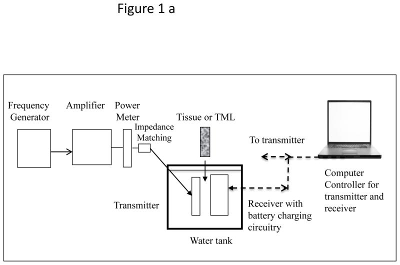
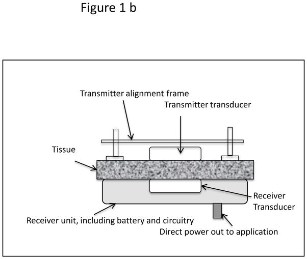
A USER system consists of an ultrasound transmitter, its power driving electronics and an implanted receiver transducer which converts acoustic to electrical energy. From that point the energy can be stored in a battery or used directly to power a therapeutic application. In order to test the energy transfer concept through 10–20 mm of tissue, two versions of implantable prototypes were developed, a tethered “Gen 1” and a wireless “Gen 2.” For simplicity, the Transmitter and Receiver transducers were planar circular discs, usually 25 mm in diameter. The transmitter was powered with a waveform generator-power amplifier combination (BK Precision 4070A, ENI 240L). The Gen 2 receiver prototype was a sealed wireless system intended as a long-term in vivo implant, hence had a biocompatible poly-ether-ether-ketone (PEEK) top shell with a stainless steel bottom plate. Transmit-receive experiments to test the efficacy of the prototypes were performed either in a tank filled with distilled water, or on a benchtop whereby excised porcine skin tissue was interleaved between the transmitter and receiver (“sandwich model”). The transmitter is placed at the top of the tissue surface using a manual tripod mechanism, so that the transmitter and receiver faces are aligned to generate optimal charge current for the battery. Schematics of the arrangement for experiments in a water tank as well as the benchtop tissue experiments are shown in the Figure 1.
Figure 1.
(a) Schematic of test set up for power transmission measurements in distilled water-filled tank. (b) Test set up of the “sandwich model.” The tissue used most frequently was excised porcine skin and subcutaneous layers. Some experiments were also performed with thick porcine muscle tissue.
Both implants were connected to a computer for bi-directional signal control. This system was coded using C++ and Signal Express (National Instruments). At the receiver, as the charging sequence is initiated, the RF signal from the piezo-transducer passes through a bridge rectifier built with discrete low forward voltage Schottky diodes. The DC is filtered, passed through a current-sense resistor, its drive voltage limited by a Zener diode. Then the DC is passed through a MOSFET device that acts as a variable current-sense resistor for the charging chip, regulating the battery charging current via varying its gate voltage. The charging chip receives its operating voltage from the rectified RF voltage.
The wireless Gen 2 prototype communicated with the controlling base station on the 405 MHz medical device wireless-band. The biocompatible PEEK-stainless steel implant was 70 mm in diameter, and contained the medical grade Li-ion 200 mA-hr battery (4.1 V maximum voltage), the charging, wireless, and microcontroller drive circuitry. The receiver RF antenna for the implant was built along the circumference inside the implant. The 1 MHz, 25 mm diameter active face ultrasound-receiver transducer was placed flush with the face of the implant. To ensure biocompatibility during survival animal studies the whole implant assembly was coated with Parylene. The transmitter transducer was matched in frequency and size to the 25 mm diameter receiver transducer. For most of the studies drive times and input RF power were in the range of 1 – 150 minutes and 0.5 – 4 W, respectively. A photograph of the designed wireless implant prototype, the medical band RF communicating base station, as well a transmitter transducer are shown in Figure 2. This system is not limited to a specific rechargeable battery, rather the charging current available from the ultrasound receiver can be used for any battery type or to drive an application directly.
Figure 2.
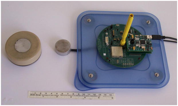
Photograph of the 70 mm diameter, medical-band wireless implant, a transmitter transducer, and the RF base station. The receiver transducer is the gray 30 mm diameter disc embedded in the center of the implant face.
3.0 Transducer selection and optimum operating frequency range
Implementation of the USER concept for transcutaneous ultrasound-based energy transfer system involved several acoustic source-target considerations. Notable aspects were focused or non-focused systems, transducer material, operating frequency, source output power, and dimensions of the transmitter and receiver. Single-element, PZT 4 and PZT 8 planar circular disc transducers in aluminum housings were constructed by American Piezo Ceramics International (APCI, Mackeyville, PA). The air backed PZT 4 and PZT 8 material discs were appropriate for high power continuous operation, due to their low loss factor. The elements were bonded with low viscosity epoxy (Hysol E120HP), to the aluminum faces to ensure good electrical and thermal contact, the Al layer thickness being impedance matched with tissue. Resonance frequencies were obtained by considering material properties and the transducers’ geometries. Transducers with thickness-resonance frequencies of 0.5 – 3.5 MHz were tested. As is commonly done (6, 11) upper and lower bounds for frequency were selected to minimize tissue heating from acoustic absorption (19) and acoustic cavitation (20, 21). During testing with lower (0.25 – 0.7 MHz) sources in a water tank, at comparable source output as described in this manuscript (maximum acoustic power output 5 W, ~1 W/cm2), bubbles were observed to coalesce at pressure maxima within the acoustic beam.
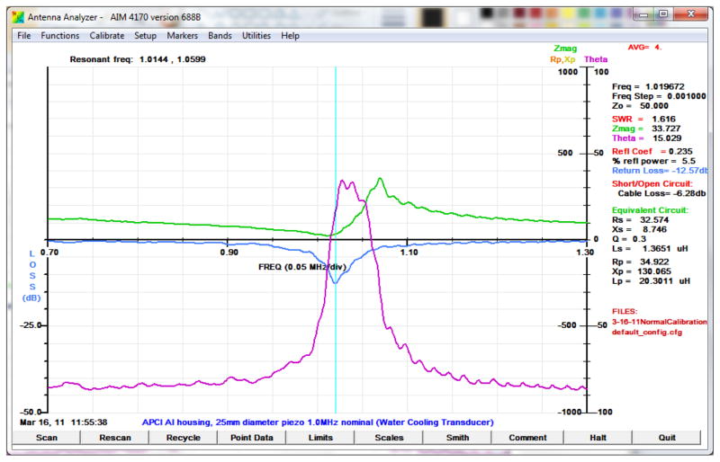
We tested the transducers individually by measurements of impedance, reflection and transmission and other parameters using a computer based antenna impedance analyzer (AIM 4170C). In the graphical result shown in Figure 3, the series resonance, thickness mode frequency was 1.019 MHz, at which the impedance was 33.7 ohms, the phase angle 15° and the reflection loss −12.6 dB. The deeper the reflection loss curve the more efficient the potential coupling between two identical transducers. Acoustic radiation from a planar source is well understood, both in the far and near fields (22) hence fields from the test transducers were assumed from literature (23–25).
Figure 3.
Antenna impedance-analyzer graphical result illustrating the variation of impedance, return loss (transmission), and phase as a function of frequency, and the Q of the resonance.
Based on results from experiments with various transmitter-receiver pairs through 1 cm of water or with a tissue mimicking material (TML) (26) an operating frequency of 1 MHz was chosen for USER. Acoustic transmitter power from planar transducers of 1 – 10 W (0.2 – 2 W/cm2) was measured using a force balance (Ohmic Instruments, Model UPM 30). This acoustic output range is similar to that used in clinical ultrasound diathermy units (23,27). The freefield of similar transducers as used in the present project has been mapped by other groups (24, 25), hence is not presented here. Repeated experiments determined the nominal electromechanical efficiency of individual transducers to be approximately 60–70%.
Regarding Mechanical Index, the acoustic source condition range used in the present study is between 1 W and 5 W, radiating from a 5 cm2 area source at 1 MHz. The corresponding calculated Mechanical Index range is therefore, between 0.08 and 0.17, calculated as described in References 28 and 29. These MI values are much lower than the AIUM recommended guidelines in the absence of any gas bodies (contrast agents).
Output from the receiver transducer was directed to charge a Li-ion battery via a charging microchip MCP73843-4.1, which charges at constant current to 4.1V (Vb), and then at constant voltage with decreasing current until the charging is complete. The power delivered to the battery was calculated as ic × Vb where ic is the charging current and Vb the battery voltage. The overall electrical to electrical system efficiency is then estimated as (ic × Vb)/Pin, where Pin is the RF power input at the transmitter measured with a Bird Corp. Thruline Wattmeter with a with a 4410-2 plug.
4.0 Apparatus and battery charging experiments in vitro
Several experiments were conducted in vitro to characterize the performance of various transmitter-receiver combinations. Keeping the source frequency of the ultrasound pairs at 1 MHz, the overall system efficiency for dimensionally matched transmitter-receiver pairs, the ratio of acoustic power input to the electrical charging power available was measured. The variables in the system that were assessed were, ultrasound source-receiver diameter, propagation medium (water, TML, or porcine skin-subcutaneous tissue), source-receiver distance (tissue thickness), and input power. Although experiments were conducted using both the Gen 1 and Gen 2 prototypes, the results reported here are from the use of Gen 1. Depending on the use of the intervening medium the experimental arrangements were as shown in Figure 1(a) [water], or Figure 1(b) [tissue].
The overall system efficiency for USER is estimated at 15 – 25%, based on the anticipated efficiency of individual system stages: transmitter transducer efficiency, 50–70%; losses due to attenuation through 1-cm of tissue at 1 MHz, 20%; efficiency of receiver transducer 50–70%; and charging circuit efficiency 50–60%. As Li-ion battery charging chips improve in efficiency, and the electro-mechanical transducer efficiencies improve, the net efficiency will increase proportionately.
For the in vitro tests of the transmitter and receiver assemblies, excised porcine tissue 5–15 mm thick, typically ~ 10 mm, was used. The tissue was composed of epidermal, dermal, fat and fascia layers. Examples of a few of the many in vitro and water tank charging experiments are shown in Table 1, with relevant parameters listed. In all cases the ultrasound frequency was 1 MHz, and a 4.1 V medical grade Li ion battery was charged.
Table 1.
Measured system efficiency with USER operating at 1 MHz, for different transducer diameters, source power, and propagating medium.
| Expt. # | Transmitter-Receiver transducer diameter (mm) | Medium | Pin (W) | Battery current (mA) | Efficiency (%) |
|---|---|---|---|---|---|
| 1 | 25 | None, direct charging | 0.6 | 93 | 50 |
| 2 | 10 | 1-cm water | 4.0 | 29 | 3 |
| 3 | 25 | 1-cm water | 4.0 | 155 | 15 |
| 4 | 40 | 1-cm water | 4.0 | 208 | 20 |
| 5 | 25 | 10 mm porcine tissue | 4.0 | 150 | 15 |
| 6* | Ti+PZT 25* | 3–5 mm porcine tissue | 2.0 | 110 | 22 |
| 7* | Ti+PZT 25* | 6–10 mm porcine tissue | 3.0 | 67 | 10 |
| 8 | 25 | 50 mm of 10 mm slices | 7.0 | 20 | 1.1 |
| 9 | 25 | 50 mm beef muscle | 7.0 | 70 | 4 |
Experiments performed with receiver transducer bonded inside a titanium pacemaker casing.
For experiments in the water tank, the temperature of the transducers was stable and the frequency did not need to be adjusted. For the in vitro experiments (and also for the in vivo tests), increasing temperature of the transmitter did cause a shift in the frequency for most efficient power transfer, typically less than 5–10 kHz. In both in vitro and in vivo experiments, the frequency was optimized manually, however in an advanced design a feedback loop would perform that function.
Experiment 1 shows the efficiency of direct 1 MHz RF input for charging (no ultrasound, no transducers), but through the same rectifier-charging chip combination, indicating a charging-circuit nominal efficiency of 50%. Newer charging chips and circuits have 85 to 90 % efficiency, which would raise the system efficiency in the future accordingly. The relative efficiencies for pairs of transducers with different diameters of piezoelectric elements are demonstrated in experiments 2, 3, and 4. Experiment 5 shows the performance when the ultrasound field is transmitted through a 10 mm-thick porcine skin tissue to the receiver. Medical implants are typically encapsulated in a titanium casing between 0.2 – 0.5 mm in thickness. The experiment 6 therefore, was performed with the receiver transducer bonded to a 0.3 mm thick titanium casing of a pacemaker. The measured charging efficiency was recorded as the transmitted beam propagated through 3–5 mm of porcine skin tissue, with a 25 mm diameter receiver piezoelectric disk bonded to titanium with conducting epoxy. The overall measured efficiency reduced correspondingly in experiment 7 when ~10 mm thick porcine tissue was the medium. Both experiments validate the practical use of incorporating a PZT-based receiver for energy transfer within a titanium implant.
Charging through greater tissue thicknesses is important in increasing the utility of the ultrasound method. In order to test the feasibility of delivering application-relevant ultrasound energy at several centimeters, experiments 8 and 9 were performed at 7 W input power with the receiver transducer located 50 mm below either a) multiple 10 mm skin thickness samples or b)a single slab of porcine muscle tissue, respectively. Charging currents recorded were 20 mA and 70 mA for composite skin-tissue or muscle tissue, respectively with transmission efficiency between 1.2 and 4%.
5.0 Battery charging in vivo
Following testing and evaluation of energy delivery in vitro, four acute in vivo studies were conducted to validate various performance requirements. In addition, in vivo prototype assessments were important to better understand the challenges of device operation in a living system. All the animal studies were conducted using a (Yorkshire) porcine model, weighing 90 – 120 lbs., under IACUC approval of a formal study protocol (Barrows Neurological Institute, Phoenix, AZ).
Key issues to investigate in vivo were, (a) establish an appropriate anatomical location for placement of the prototype implant; (b) establish a surgical approach to place the implant, such that it is does not migrate during the testing; (c) understand the logistical requirements for device performance and alignment of the transmitter and the receiver transducers, accounting for respiratory movement of the animal; (d) achieve effective coupling of the transmitter transducer to the skin surface, (e) record the temperature increase(s) at various points in the path of the transmitter and receiver, especially since the skin tissue is perfused with cutaneous tissue temperature of 32 – 34°C, (10 – 12°C higher than the room temperature); (f) test requirements of active or passive cooling of the tissue exposure site and the prototypes, since there are multiple factors which effect a temperature increase within a transducers’ path in vivo. For the acute porcine validation, Gen 1 was used, whereas the wireless Gen 2 was deployed for the 25-day survival porcine study.
5.1 Tissue temperature considerations
It is critical to observe and understand the macroscopic as well as histological response of live skin and subcutaneous tissue to USER energy delivery, especially over at least several 10s of minutes. While there are well known simple guidelines advising levels for brief safe temperature excursions for pulsed diagnostic ultrasound, exposure to the body from continuous (relatively low acoustic intensity) ultrasound for systems as described here are not well characterized. A nomograph in Sapareto and Dewey (30) shows that a specific bioeffect is dependent on the product of the temperature excursion and the longevity of that excursion. A University of Minnesota group headed by Dr. E. Sparrow has published extensively (for example Reference 31) on modelling of the heating caused by continuous wave, induction-based, commercially available, clinical neurostimulator recharger products made by major manufacturers. Their analysis of the potential for tissue damage (32), based on the Henrique-Moritz cell injury criterion (33) confirmed that the product of the temperature excursions and its duration is indeed the operative criterion. Considerations like these apply to the USER™ method as well. In the present studies, power limitations and post-exposure histology have been used to prevent and assess tissue damage respectively.
When temperature excursions were the point of an experiment, they were measured in four locations, at the top of the transmitter housing, close to the interface of the transmitter with the skin, next to the receiver transducer in the implant, and at the backplate of the implant. We also observed a phenomenon which has not been reported, perhaps because cooling of the transmitter has not been used in practice. With continuous transmitter cooling and the transmitter in contact with the skin (or even through a 1 cm thick gel pad), the cooling front propagates into the intervening tissue and to the implant, mitigating temperature rise due to its heat load. Data demonstrating this effect will be presented below.
5.2 Acute porcine studies
The acute porcine experiments were conducted in a surgical suite, under the supervision of a trained surgeon assisted by veterinary surgical staff. The animal was sedated prior to the procedure and the respiratory and cardiovascular functions were maintained using established large animal surgical protocols. The animal was euthanized at the end of the study, and the exposed tissue was harvested for histological evaluation by an experienced veterinary pathologist (Univ. of Arizona, Tucson). In order to place the receiver prototype implant, a 50 – 60 mm incision was made at the selected site on the body of the animal. A pocket was made 10 – 15 mm deep subcutaneously until a plane just superior to the muscle and fascial plane was reached through blunt dissection. About 30 cc of ultrasound coupling gel was placed on the receiver transducer and the implant inserted in the surgically created pocket. Following insertion, the incision was sutured closed. Based on the access to a flat surface where the transmitter can be placed and affixed, well aligned to the receiver, the more taut para-vertebral torso and flank areas were most suitable for the experiments. The softer ventral side of the porcine specimen had thin overlying skin tissue, and it was difficult to anchor the receiver implant in the loose fatty-connective tissue. At this site, the power transmitting transducer was not effective in being attached and aligned to the receiver in a predictable manner.
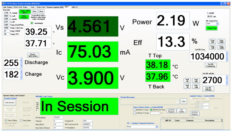
A computer user interface shown in Figure 4 was designed for these and the survival study. It prominently displayed the readouts of the voltage out of the rectifiers (Vs), the cell (battery) charging current (Ic) and voltage (Vc), and several temperatures that were monitored during the studies. On the right side are the estimated real-time efficiency and the transmitter frequency. The transmitter frequency was changed via the interface to compensate for frequency shifts due to heating of the transmitter. In the first acute study, the goal was to demonstrate 30 minutes of continuous stable power delivery while testing the different parts of the charging system shown schematically in Figure 1. A transmitter assembly was placed over the profile of the receiver which was implanted 10–15 mm under the surface of the skin. Alignment was achieved manually via three adjustment screws. The implant was tethered to the controller which was connected to the nearby laptop computer for communication with the implant and relay of data to the computer. The longest duration of steady current was about 33 minutes at ~70 mA. For a few minutes 125 mA of current was applied to the battery.
Figure 4.
The user interface.
The 2nd study focused on testing Gen 1 temperatures with both Peltier and water cooling, the latter with the water in contact with the skin, contained by a rubber gasket seal to the skin. Neither cooling method was practical and both were abandoned. Instead a closed-circuit single-loop water cooling coil was embedded around a conical skirt on the transmitter assembly. With chilled water running through the coil, significant cooling all of the way through the tissue to the receiver was easily achieved. Miniature closed-cycle water cooling systems have been used in high-intensity focused ultrasound (HIFU) applications, and in cooling computer CPUs. Attaching such a cooler to a transmitter unit is possible.
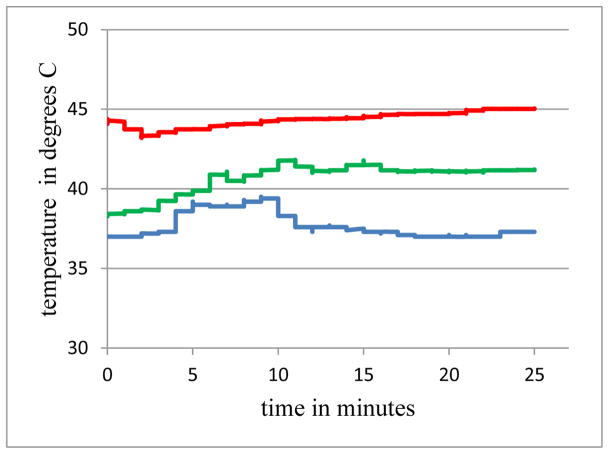
In the 3rd acute study repetitive experiments were performed to determine the maximum power that could be transferred for at least 25 minutes without tissue damage. Figure 5 shows the temperatures over 25 minutes for three cases, at the face of the implant next to the receiver transducer. The 0 minutes mark is when stability was achieved in each experiment, which is why they do not all begin at core temperature. The middle trace represents data from an input power of 3.3 W, charging for 29 minutes at ~ 80 mA, no cooling, with a temperature rise of 2.3 C at the front of the implant. When the input power was raised to 4.4 W (again no cooling) and charging current to 115 mA, as expected, the temperature rise was higher, 6.3 C (upper trace). When the closed circuit water cooling was applied to the latter case of 4.4 W and 120 mA, the temperature at the front of the implant only increased by 0.5 C (lower trace). This illustrates the extraction of heat at the implant due to external cooling.
Figure 5.
Temperatures at the face of the receiver for three cases with differing input power Pin and cooling: Upper: Pin = 4.4 W, no cooling; Middle: Pin = 3.3 W, no cooling; Lower: Pin = 4.4 W, with cooling.
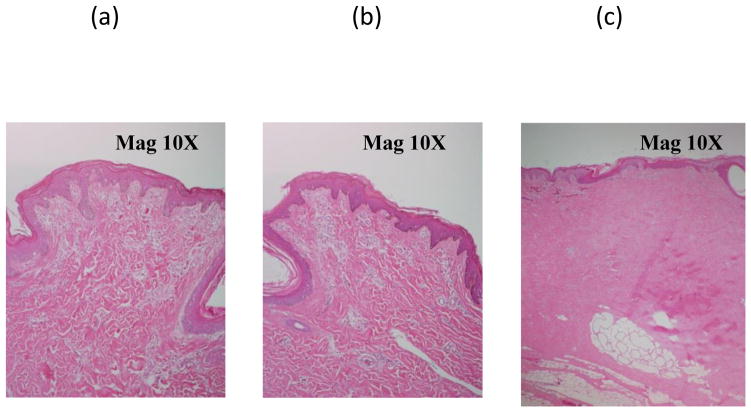
Histology on two exposed samples (from first and last exposures above) shown in Figure 6 a,b, confirmed the absence of tissue damage due to ultrasound in both cases. To show what can occur with excess heating, in an earlier experiment, when skin tissue was subjected to continuous exposure at input power of 9.5 W without cooling for 25 minutes, significant heating of the skin surface resulted (45 C). During histological evaluation, substantial coagulation of dermal and subcutaneous tissue was recorded (Figure 6 c). Maximum recorded charge current was about 75 mA, much lower than the earlier experiments, possibly due to the increased absorption of the intervening tissue due to coagulation.
Figure 6.
Acute porcine skin and subcutaneous histology from post-exposure regions following transmission of ultrasound. (a, left) Experiment with 80 mA charging current without cooling. (b, center) Experiment with 110 mA charging current with active chilled-water cooling. The previous two showed no indications of thermal coagulative changes. (c, right) In contrast, a tissue sample showing significant coagulation due to 25 minutes of 45 C exposure.
The time in the 4th acute test was spent on testing miniaturized transmitters, with useful but unremarkable results.
5.3 Porcine survival study
In order to demonstrate the capability to successfully implant a wireless prototype in situ and repeatedly charge the Li-ion battery within the implant, a survival porcine model study was implemented. As earlier, the test specimen was a Yorkshire pig, weighing approximately 130 lbs, and the study was conducted with IACUC approval. The animal was anesthetized and under cardiovascular and respiratory stabilization during each experimental session. Key technical requirements for the study were: surgical implantation and fixation of the wireless receiver prototype shown in Figure 7 under full aseptic precautions; biocompatibility of the implant to avoid its rejection by the host; good acoustic coupling of the implant with the transmitter; bi-directional communication and control capability. The latter allowed charging the implanted Li-ion battery, rapidly discharging the battery, and monitoring a number of device parameters, such as various voltages and temperatures within the receiver. In addition to the active charging tests, the tissues response from an ultrasound field reflected off a 0.5 mm thick titanium (Ti) plate were also investigated in vivo. A secondary source transducer operating at the same power output conditions as the transmitter for the charger implant, was incident on the Ti plate. This test provided a reasonable comparison with the tissue response resulting from the transmitter beam incident on metal with and without charging in progress. No difference in tissue response was observed. Figure 7a illustrates the Gen 2 receiver unit being implanted. Figure 7b shows the transmitter over the wireless implant.
Figure 7.
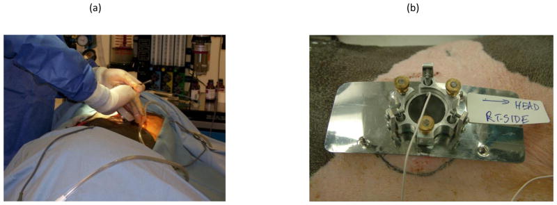
a: Implanting the receiver unit. b. The transmitter unit.
The overall duration of the survival study was 25 days. Events during each session are listed in Table 2.
Table 2.
Event chart for survival porcine study.
| Day 1 | Surgical implantation of receiver and Ti plate and wound closure; battery charging; exposure on Ti plate. |
| Days 6, 11, 15 | Rapid discharge of battery; battery charging; exposure on Ti plate. |
| Day 25 | Euthanize specimen; excision and fixing of overlying skin subcutaneous tissue. Gross observation, and submission of samples for histopathology assessment |
The transmitter in a mechanically adjustable stage was placed on the porcine skin over the receiver transducer with coupling gel between them, and was taped in place using atraumatic compression tape. Cooling of the site was not used because of the low power levels, and any temperature excursions not mitigated by perfusion seem not to have adversely affected the intervening tissue. The transmitter was aligned to the receiver using set-screws on the stage. Each day there was an initial period of 5–15 minutes adjusting the alignment to maximize efficiency of power transfer. Following the last charging session on Day-15, the animal survived for another 10 days, in order for the exposed regions to recover from experimental manipulation of the target sites. The charging parameters for the individual charging sessions are shown in Table 3.
Table 3.
Important parameters for the four separate days of charging.
| I cell avg (A) | Pin avg (W) | Eff avg (%) | charging time | |
|---|---|---|---|---|
| Day 1 | 0.076 | 2.0 | 15% | 2hrs 40 min |
| Day 6 | 0.078 | 1.3 | 24% | 2 hrs 30 min |
| Day 11 | 0.075 | 1.4 | 21% | 2 hrs 40 min |
| Day 15 | 0.073 | 1.4 | 21% | 2 hrs 40 min |
| 20% | 10.5 hrs |
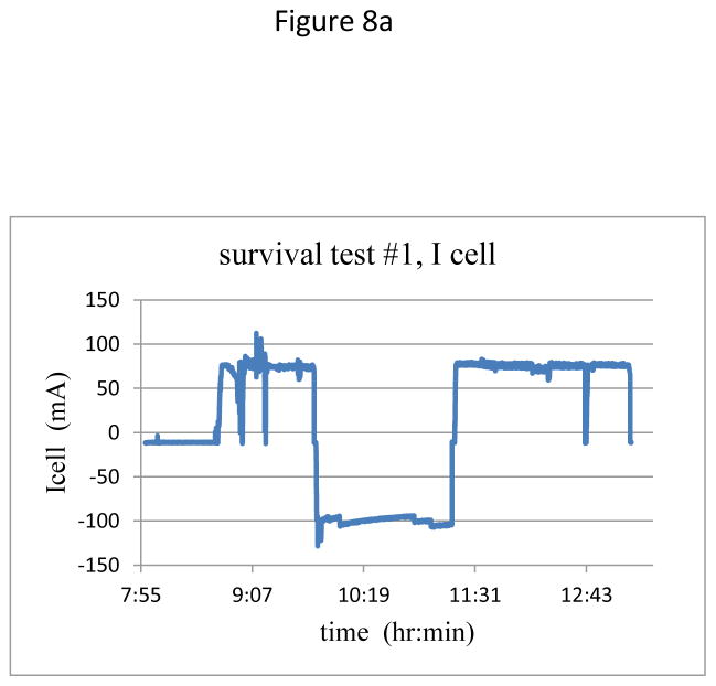
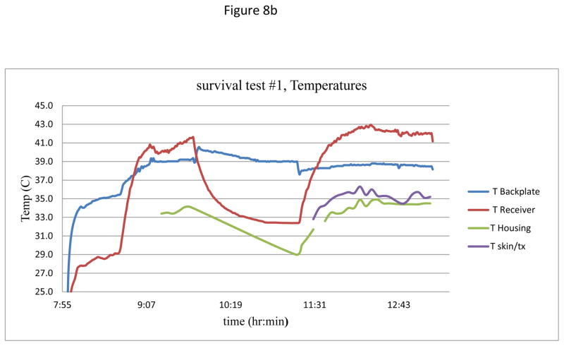
With minor variations due to reattaching the transmitter on each day, temporal plots of current and temperatures were similar for the four charging days. Figure 8 shows a representative plot of the charging current during the session on Day 1, as well as the recorded temperatures at various points within the ultrasound beam path. The skin surface temperature was 33°C, while the core temperature of the animal was 37°C.
Figure 8.
(a) Charging current over two cycles of charging – discharging – charging.
(b) Measured temperatures at various points in the acoustic beam.
Figure 8(a) shows the typical two-cycles of charging each day, with a period of about an hour of discharging in the middle. After initial alignment, the current stabilized at close to 75 mA, and in the second charging period was stable for over 60 minutes. In Figure 8b the lowest two traces are temperatures of the transmitter housing and at the transmitter-skin interface, both with virtually no increase during the charging times. The upper two traces are for the receiver showing, at the start of the second charging period at the receiver face, an excursion to 42.5 C, ~5.5°C higher compared to the ambient core temperature. This temperature excursion is the same as calculated for one of the inductive charging systems now in clinical use (32), while the backplate of the receiver assembly in the present study showed a rise of less than 1.5 C during an active session. Future improvements in the receiver circuitry and transducer materials should further reduce heating. Redesign will include the use of custom diodes to reduce losses at the rectifier, as well as using components to more effectively regulate the charge controller at the transistor. Finally, the lower losses in the receiver circuit will reduce the transmit power requirements, thereby further reducing the overall heating at the receiver.
Over the period of the exposures no changes on the skin surface were observed in terms of breaching of epidermis or stiffening of the subcutaneous tissue, indicative of tissue coagulation. Tissue histology was performed for the regions over the active implant as well as the region where the Ti plate was placed. The significant histologic response in both regions was the infiltrative, granulation tissue primarily due to the substantial foreign bodies introduced subcutaneously. No significant tissue coagulation changes were observed histologically in the active implant region, except regenerative cellular changes in the epidermis and dermis, indicative of chronic injury potentially from the invasive procedure. These results are consistent with those of clinical ultrasound diathermy units, where transmitter acoustic powers of 0.5 – 10 W (0.2 – 2 W/cm2) are used over time period 0.5 – 4 hours clinically (23,24,27). Their devices passed safety and performance evaluations in accordance with IEC and FDA regulations (24,27). Note that implants in humans are much smaller than the prototype dimensions used here. Hence trauma due to implantation will be minimal for clinical applications, compared to our large prototype.
6.0 Conclusions
With these described in vitro and in vivo studies, the capability to insert an implant with a medical grade Li-ion battery and repeated charging of the battery has been demonstrated. Through benchtop and in vivo testing, this investigation simulated the potential use of an USer-based charging approach in implants. In vitro, charging currents up to 150 mA were realized, corresponding to 600 mW delivered to the battery. Charging currents of up to 75 mA in vivo (300 mW) were adequate to charge a 50% depleted, 4.1 V battery within less than 2 hours. Temperature increases recorded at various locations within the acoustic beam were normally between 2 – 5°C. Apparatus that wirelessly transmits these powers through 1–2 cm of animal tissue to charge a battery in an implantable device has been described. To our knowledge this is the first 10hr+ accumulated exposure survival study report with detailed multiple site temperature measurements, and with strong implications of the safety of this method.
While these results are promising, much work remains to be done to make this a useful technique. A major advantage of ultrasound recharging is that arrays can be used to perform angular scans non-mechanically to optimize power transfer (7,18). Well known array methods in ultrasound allow for beam or wavefront steering via phase difference insertion between the array elements. Since the phase difference can be inserted electronically and connected to a feedback loop, this offers the possibility of completely non-mechanical misalignment adjustment, at least over the angles likely to be found in practice between 25 mm diameter transducer faces. With the sizes of coils and frequencies commonly used in inductive coupling (6, p. 19), such non-mechanical scanning is unlikely. But non-mechanical alignment using transmitter transducer arrays remain to be tested. Miniaturization and pre-clinical demonstration of the USer approach within an implant form factor used in the clinic is the next step of development. Considerably more studies involving tissue exposure and histology are required to confirm conclusions reported in this investigation. A portion of the rapidly growing set of neurostimulator applications could be an appropriate target for introduction of this recharging method.
Highlights.
Demonstrated in vitro up to 0.6 W of transcutaneous power transfer using ultrasound to an implantable receiver unit.
Optimized the operation of Ultrasound Electrical Recharging (USER) system for operation in vitro and in vivo in porcine tissue.
Developed practical cooling options that resulted in heat extraction even from the implanted receiver unit.
Demonstrated delivery of ultrasound energy to charge a medical grade battery during acute porcine studies and a 25-day survival experiment, with no histological findings related to thermal coagulation due to ultrasound exposure.
Acknowledgments
We acknowledge the support of Mr. Harry Jabs in designing the implant prototypes for the project. The project was funded by the National Institutes of Health - National Institute of Bioimaging and Bioengineering, under grants R43EB007421 and R44EB007421. The conclusions stated in this publication are solely those of the authors and not of the National Institutes of Health.
Footnotes
Publisher's Disclaimer: This is a PDF file of an unedited manuscript that has been accepted for publication. As a service to our customers we are providing this early version of the manuscript. The manuscript will undergo copyediting, typesetting, and review of the resulting proof before it is published in its final citable form. Please note that during the production process errors may be discovered which could affect the content, and all legal disclaimers that apply to the journal pertain.
Contributor Information
Leon Radziemski, Piezo Energy Technologies LLC, 5153 N Via Velazquez, Tucson, AZ 85750 USA.
Inder Raj S. Makin, A. T. Still University, Mesa, AZ 85215
Bibliography and References
- 1.Mallela VS, Ilankumaran V, Rao NS. Trends in cardiac pacemaker batteries. Indian Pacing and Electrophysiology J. 2004;4:201–212. [PMC free article] [PubMed] [Google Scholar]
- 2.Schulman JH. Stimulating and sensing network inside the human body. J of Comm. 2007;2:73–78. [Google Scholar]
- 3.Root MJ. Implantable cardiac rhythm device batteries. J Cardiovasc Trans Res. 2008;1:254–257. doi: 10.1007/s12265-008-9054-9. [DOI] [PubMed] [Google Scholar]
- 4.Schuder JC. Powering an artificial heart: Birth of the inductively coupled-radio frequency system in 1960. Artif Organs. 2002;26:909–915. doi: 10.1046/j.1525-1594.2002.07130.x. [DOI] [PubMed] [Google Scholar]
- 5.Van Schuylenbergh K, Puers R. Inductive powering: Basic theory and application to biomedical systems. Springer; 2009. See Ch. 1 and 2 pages 1–74 for background; p. 19 for typical transfer frequency. [Google Scholar]
- 6.Ozeri S, Shmilovitz D. Ultrasonic transcutaneous energy transfer for powering implanted devices. Ultrasonics. 2010;50:556–566. doi: 10.1016/j.ultras.2009.11.004. [DOI] [PubMed] [Google Scholar]
- 7.Mazzilli C, Lafon C, Dehollain C. A 10.5 cm ultrasound link for deep implanted medical devices. IEEE Trans Biomed Circuits and Sys. 2014;8:738–750. doi: 10.1109/TBCAS.2013.2295403. [DOI] [PubMed] [Google Scholar]
- 8.Goto K, Nakagawa T, Nakamura O, Kawata S. An implantable power supply with an optically rechargeable battery. IEEE Trans on Biomed Eng. 2001;48:830–833. doi: 10.1109/10.930908. [DOI] [PubMed] [Google Scholar]
- 9.Clark WW, Ramsay MJ. Smart materials transducers as power sources for MEMS devices. Int. Symp. on Smart Structures and Microsys; October 19–21; 2000. pp. 1–8. [Google Scholar]
- 10.Mo C, Radziemski LJ, Clark WW. Performance comparison of implantable piezoelectric energy harvesters. SPIE Smart Structures and Materials & Nondestructive Evaluation and Health Monitoring conference; San Diego. Proc. of the SPIE 6928; 2008. pp. 69280C-1–10. Paper No. 6928-1. [Google Scholar]
- 11.Ozeri S, Shmilovitz D, Singer S, Wang CC. Ultrasonic transcutaneous energy transfer using a continuous wave 650 kHz Gaussian shaded transmitter. Ultrasonics. 2010;50:666–674. doi: 10.1016/j.ultras.2010.01.004. [DOI] [PubMed] [Google Scholar]
- 12.Cotté B, Lafon C, Dehollain C, Chapelon J-Y. Theoretical study for safe and efficient energy transfer to deeply implanted devices using ultrasound. IEEE Trans Ultras Ferro Freq Contr. 2012;59:1674–1686. doi: 10.1109/TUFFC.2012.2373. [DOI] [PubMed] [Google Scholar]
- 13.Kawanabe H, Katene T, Saotome H, Saito O, Kobayashi K. Power and information transmission to implanted medical device using ultrasonics. Jpn J Appl Phys. 2001;40:3865–3866. [Google Scholar]
- 14.Suzuki S, Kimura S, Katane T, Saotome H, Saito O, Kobayashi K. Power and interactive information transmission to implanted medical device using ultrasonic. Jpn J Appl Phys. 2002;41:3600–3603. [Google Scholar]
- 15.Rosen CA, Fish KA, Rothenberg HC. Electromechanical transducer. 2,830,274. US Patent. 1958
- 16.Denisov A, Yeatman E. Ultrasonic vs. inductive power delivery for miniature biomedical implants. Proc. Int. Conf. Body Sensor Networks; June (2010); pp. 84–89. [Google Scholar]
- 17.Radziemski LJ. Bio-implantable ultrasound energy capture and storage assembly including transmitter and receiver cooling. 8,082,041. US Patent. 2011
- 18.Radziemski LJ, Makin IRS. High Power Ultrasound Wireless Transcutaneous Energy Transfer (US-TET) Source. 8,974,366. U S Patent. 2015
- 19.Damianou CA, Sanghvi NT, Fry FJ, Maass-Moreno R. Dependence of ultrasonic attenuation and absorption in dog soft tissues on temperature and thermal dose. J Acoust Soc Am. 1997;102:628–634. doi: 10.1121/1.419737. [DOI] [PubMed] [Google Scholar]
- 20.Child SZ, Hartman CL, Schery LA, Carstensen EL. Lung damage from exposure to pulsed ultrasound. Ultrasound in Med & Biology. 1990;16:817–825. doi: 10.1016/0301-5629(90)90046-f. [DOI] [PubMed] [Google Scholar]
- 21.Holland C, Apfel R. An improved theory for the prediction of microcavitation thresholds. IEEE Trans Ultrasonics, Ferroelectrics, and Frequency Control. 1989;36:204–208. doi: 10.1109/58.19152. [DOI] [PubMed] [Google Scholar]
- 22.Cobbold RSC. Foundations of Biomedical Ultrasound. Oxford Press; 2007. pp. 155–163. [Google Scholar]
- 23.Lewis GK, Jr, Langer MD, Henderson CR, Jr, Ortiz R. Design and evaluation of a wearable self-applied therapeutic ultrasound device for chronic myofascial pain. Ultras Med Bio. 2013;39:1429–1439. doi: 10.1016/j.ultrasmedbio.2013.03.007. [DOI] [PubMed] [Google Scholar]
- 24.Straub SJ, Johns LD, Howard SM. Variability in effective radiating area at 1 MHz affects ultrasound treatment intensity. Physical Therapy. 2008;88:50–57. doi: 10.2522/ptj.20060358. [DOI] [PubMed] [Google Scholar]
- 25.Tsuruta JK, Dayton PA, Gallippi CM, O’Rand MG, Streicker MA, Gessner RC, Gregory TS, Silva EJ, Hamil KG, Moser GJ, Sokal DC. Therapeutic ultrasound as a potential male contraceptive: power, frequency and temperature required to deplete rat testes of meiotic cells and epididymides of sperm determined using a commercially available system. Reprod Biol Endocrinol. 2012;10:7. doi: 10.1186/1477-7827-10-7. [DOI] [PMC free article] [PubMed] [Google Scholar]
- 26.Burlew MM, Madsen EL, Zagzebski JA, Banjavic RA, Sum SW. A new ultrasound tissue-equivalent material. Radiology. 1980;134:517–520. doi: 10.1148/radiology.134.2.7352242. [DOI] [PubMed] [Google Scholar]
- 27.Langer M, Fleshman S, Taggart R, Gu Y, Lewis G. Bench and animal testing of a wearable long-duration therapeutic ultrasound device. J Ultrasound Med. 2014;(suppl):S9. 1847065. [Google Scholar]
- 28.Fowlkes JB, Holland CK. Discussion of the mechanical index and other exposure parameters. J Ultrasound Med. 2000;19:143–148. doi: 10.7863/jum.2000.19.2.143. [DOI] [PMC free article] [PubMed] [Google Scholar]
- 29.Nelson TR, Fowlkes JB, Abramowicz JS, Church CC. Ultrasound biosafety considerations for the practicing sonographer and sonologist. J Ultrasound Med. 2009;28:139–150. doi: 10.7863/jum.2009.28.2.139. [DOI] [PubMed] [Google Scholar]
- 30.Sapareto SA, Dewey WC. Thermal dose determination in cancer therapy. Int J Radiat Oncol Biol Phys. 1984;10:787–800. doi: 10.1016/0360-3016(84)90379-1. [DOI] [PubMed] [Google Scholar]
- 31.Weinmann JJ, Sparrow EM. Heat flow from rechargeable neuromodulation systems into surrounding media. Neurmod Tech at the neural Interf. 2009;12:114–121. doi: 10.1111/j.1525-1403.2009.00198.x. [DOI] [PubMed] [Google Scholar]
- 32.Lovik RD, Abraham JP, Sparrow EM. Potential tissue damage from transcutaneous recharge of neuromodulation implants. Int J of Heat and Mass Transfer. 2009;52:3518–3524. [Google Scholar]
- 33.Henriquez FC, Moritz AR. Studies of thermal injury I: the conduction of heat to and through the skin and the temperature attained therein. A theoretical and experimental investigation. Am J Pathol. 1947;23:531–549. [PMC free article] [PubMed] [Google Scholar]


