

Abstract
Background:
Orthodontic tooth movement is a complex procedure that occurs due to various biomechanical changes in the periodontium. Optimal orthodontic forces yield maximum tooth movement whereas if the forces fall beyond the optimal threshold it can cause deleterious effects. Among various types of tooth movements intrusion and lingual root torque are associated with causing root resoprtion, especially with the incisors. Therefore in this study, the stress patterns in the periodontal ligament (PDL) were evaluated with intrusion and lingual root torque using finite element method (FEM).
Materials and Methods:
A three-dimensional (3D) FEM model of the maxillary incisors was generated using SOLIDWORKS modeling software. Stresses in the PDL were evaluated with intrusive and lingual root torque movements by a 3D FEM using ANSYS software using linear stress analysis.
Results:
It was observed that with the application of intrusive load compressive stresses were distributed at the apex whereas tensile stress was seen at the cervical margin. With the application of lingual root torque maximum compressive stress was distributed at the apex and tensile stress was distributed throughout the PDL.
Conclusion:
For intrusive and lingual root torque movements stress values over the PDL was within the range of optimal stress value as proposed by Lee, with a given force system by Proffit as optimum forces for orthodontic tooth movement using linear properties.
Keywords: Finite element method, intrusion, linear analysis, lingual root torque, optimum force
Introduction
Orthodontic tooth movement is a complex procedure that occurs due to various biomechanical changes in the periodontium. Proffit et al. stated that “tooth movement is primarily a periodontal ligament (PDL) phenomenon.”1 Various clinical and laboratory studies have attempted to relate the forces applied to the tooth with the quality and speed of the tooth movement produced.2-4 The finite element method (FEM) is the most suitable means of analysis, because of its ability to handle various shapes and materials of non-homogenous nature. Incisor intrusion and lingual root torque have been known to cause deleterious effects to teeth such as root resorption. According to Proffit et al., the optimum force for intrusion is 10-20 g and for root movement it is 50-100 g.1 Intrusive, as well as torquing forces are damaging to the root surfaces, as substantial force is required to torque the apex of the maxillary central incisor lingually. These torquing forces are concentrated at a small area around the apex which is resorption sensitive.5 Therefore, the purpose of this study is to assess the stresses in PDL and to evaluate the risk of root resorption on the application of intrusive and torque movements using three-dimensional (3D) FEM.
Aims and objectives
To evaluate the distribution of stress pattern in PDL on application of orthodontic load (vertical intrusive force and lingual root torque) on maxillary central incisors with a 3D finite element analysis using linear properties
To determine the optimal forces for intrusive and lingual root torque movements in relation to previous clinical, laboratory and histological studies.
Materials and Methods
In this study a 3D finite element model of a maxillary central incisor was created and used to calculate the stress in the PDL and evaluate the risk of root resorption by application of intrusive and torque movements by a 3D FEM and compare these stresses in the PDL using linear analysis.
Computational facilities used for the study
Hardware: A PC workstation having an Intel Core DUO processor with 8 GB RAM, 500 GB secondary storage and graphic accelerator were used for the study.
Software: The design program: SOLIDWORKS release 2012; 3D modeling software, and FEA program: ANSYS workbench was used for this study.
Steps involved in the generation of finite element model
Construction of a geometric model
Conversion of the geometric model to a finite element model
Material property data representation
Defining the boundary condition
Loading configuration
Solving the system of linear algebraic equation
Interpretation of the results.
Construction of a geometric model
The purpose of the geometric modeling phase is to represent a geometry in terms of points (grids), line surfaces (patches), and volume (hyper patches). In this study, the analytical model incorporating maxillary central incisor along with PDL, cortical and compact bone were developed according to dimensions and morphology found in a standard textbook of Dental Anatomy, Physiology, and Occlusion by Wheeler’s.6 PDL was simulated as a 0.2 mm thick ring around the model of the tooth and cortical bone at 0.5 mm thick (Figure 1a).7 With software SOLIDWORKS surfaces were generated and this data was exported in Initial Graphics Exchange Specification (IGES) format to ANSYS workbench.
Figure 1.
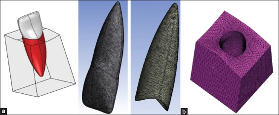
(a) Geometric model of maxillary central incisor and supporting structures in SOLIDWORKS software, (b) model showing elements and nodes distribution (1,48,097 elements and 2,39,666 nodes).
Conversion of geometric model to finite element model
This geometric model in IGES format was imported into Macmesh. A finite element model is created using discretization technique. The finite element model approximately consisted of 1,48,097 tetrahedral elements 2,39,666 nodes and 3 degrees of freedom (Figure 1b).
Material property data representation
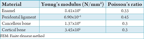
Each structure was then assigned a specific material property. The different structures in the finite element model are tooth, PDL, cortical bone, and cancellous bone. The material properties used in this study have been taken from finite element studies previously conducted.8 These material properties were defined as linear and isotropic for linear analysis (Table 1).9
Table 1.
Linear material properties used in FEM.
Defining the boundary condition
The boundary condition, in the finite element model was defined at all the peripheral nodes of the bone with three degree of movement in all directions. Boundary conditions were assigned to the nodes surrounding the outermost layers of the tooth, roots and alveolar bone. The geometry of the tooth root and of the alveolus has to be kept constant during the movement.
Application of forces
The loading configuration was designed to simulate conventional orthodontic tooth movement.
Application of forces in this study was the same as used previously by Puente et al. and Rudolph et al.10,11 They were also within the range of optimum forces for orthodontic tooth movement proposed by Proffit et al.1 Intrusion and lingual root torque were applied at various points of the crown surface. Intrusion was modeled by applying 20 g of force directed along the long axis of the tooth (Figure 2a). To obtain lingual root torque, it was necessary to apply a couple, to create a moment (the moment of a couple or Mc) equal in magnitude and opposite in direction to the original movement. Therefore, 15 N/mm of lingual root torque was applied (Figure 2b).
Figure 2.
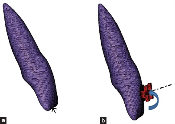
(a) Load application along the long axis of the tooth, (b) load application for lingual root torque.
Solving the system of linear algebraic equations
The sequential application of the above steps leads to a system of algebraic equations where the nodal displacements are unknown. These equations are solved by frontal solver technique present in the ANSYS workbench software.
Results
The forces were applied on the maxillary central incisor for intrusive and lingual root torque movements, and the equations were solved with linear properties by ANSYS workbench software and sequentially the stress patterns produced in PDL were analyzed.
The results obtained were divided into the following;
Application of intrusive force of 0.20 N using linear properties
Application of intrusive force of 0.30 N using linear properties
Application of lingual root torque of 0.88 N/mm using linear properties
Application of lingual root torque of 1.00 N/mm using linear properties.
Application of intrusive force of 0.20 N using linear properties
When 0.20 N of intrusive forces were applied along the long axis of the tooth it produced minimum compressive stress (denoted as minus) as −0.01337 N/mm2 at the apex of the PDL and the maximum tensile stress at the cervical margin was 0.001018 N/mm2 (Figure 3). Since In this case the compressive stresses were lesser than the range given by Lee12 (0.015-0.026 N/mm2). Therefore iteration was done, and the force level was increased to 30 g.
Figure 3.
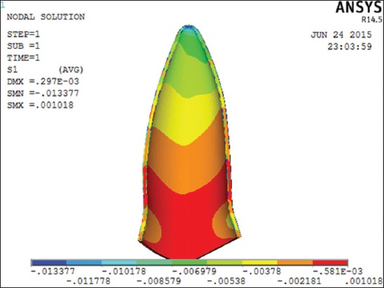
Distribution of principle stress in periodontal ligament on the application of the intrusive force of 0.20 N using linear properties.
Application of intrusive force of 0.30 N using linear properties
When 0.30 N of intrusive forces were applied along the long axis of the tooth it produced minimum compressive stress of −0.02006 N/mm2 at the apex of the PDL and the maximum tensile stress was 0.001528 N/mm2 at the cervical margin (Figure 4). In this case, it was noted that the stress was in the range of optimal stress range provided by Lee.12
Figure 4.
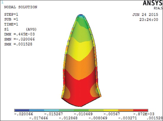
Distribution of principle stress in periodontal ligament on the application of the intrusive force of 0.30 N using linear properties.
Application of lingual root torque of 0.88 N using linear properties
When 0.88 N force with 15 N/mm moment load was applied using linear properties, it produced minimum compressive stress as −0.0144 N/mm2 and the maximum tensile stress was 0.016123 N/mm2. This produced a lingual root torque (Figure 5). Here, the compressive stresses were lesser than the optimal stress range, hence iterations were done till 1.0 N.
Figure 5.
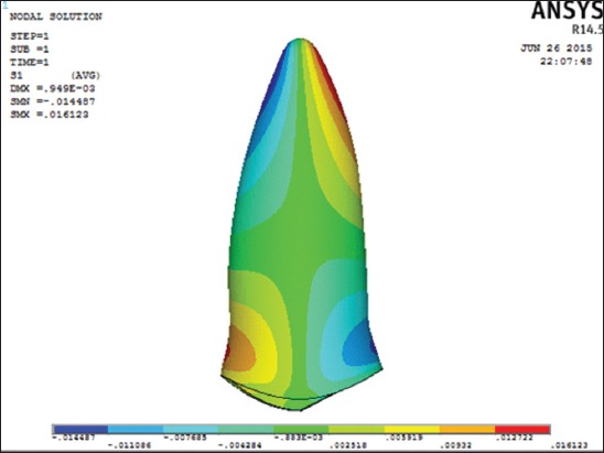
Distribution of principle stress in periodontal ligament on the application of lingual root torque of 0.88 N/mm using linear properties.
Application of lingual root torque of 1.0 N using linear properties
After application of 1.0 N of lingual root torque the compressive and the tensile stresses were −0.01646 N/mm2 and 0.01832 N/mm2 respectively (Figure 6). Here, the compressive stresses were within the optimal stress range given by Lee.12
Figure 6.
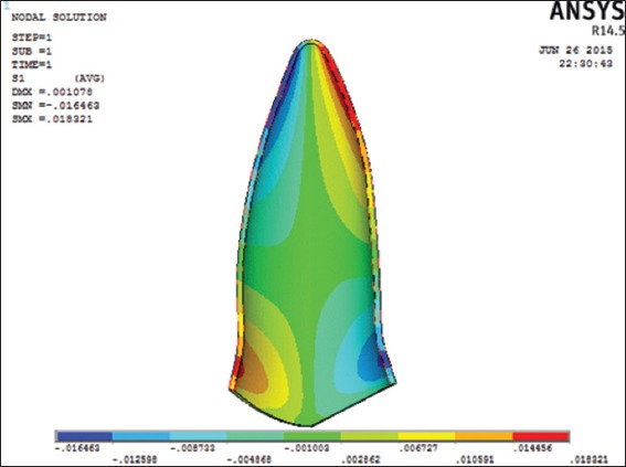
Distribution of principle stress in periodontal ligament on application of lingual root torque of 1.00 N/mm using linear properties.
Discussion
This study investigated the magnitude and stress pattern in the PDL for intrusion and lingual root torque by means of the FEM. Because of the importance of the distribution of the stress in the PDL, in this study, we focused on analysis of the biomechanical characteristics of the changes in the PDL. Clinical studies report a slight loss of periodontal attachment in adolescents and adults during treatment with fixed orthodontic appliances.6,13,14 Using a FEM model, the present study quantifies the stresses on PDL with intrusion and lingual root torque. This study shows that intrusive forces and lingual root torque produces stress at the root apex. Similar results were found in previous investigations for vertical tooth movement that used FEM.11,15,16
In clinical observation, it might be expected that for intrusive forces only compressive stresses are seen over the whole PDL. However, in our study it was seen that when the intrusive force of 0.20 N was applied using linear properties, the compressive stress was seen only at the apex whereas tensile stresses were distributed along the cervical margin. The stress profiles in our study were similar to other finite element studies by Rudloph et al. and Wilson et al.11,16
For 0.20 N of intrusive forces applied along the long axis of the tooth, the maximum compressive stress of −0.0133 N/mm2 were seen at the apex of the PDL and the maximum tensile stress of 0.0010 N/mm2 at the cervical margin (Figure 3). In this situation, the stresses were lesser than the optimal stress range provided by Lee.12
When 0.30 N of intrusive forces were applied along the long axis of the tooth it produced minimum compressive stress of −0.02006 N/mm2 at the apex of the PDL and the maximum tensile stress of 0.0015 N/mm2 at the cervical margin (Figure 4). Therefore in this case, the stress was in the range of optimal stress range provided by Lee.12
In the present study intrusive stresses produced with the application of optimal forces proposed by Proffit et al. were below the optimal stress values suggested by Lee.12 However, stress values found were higher in comparison to the results of the study by Rudolph et al. (−0.0017 N/mm2) although in both the studies the magnitude of force applied was the same.11 The high stresses produced in the present study were due to the forces being applied along the long axis of the tooth as against to forces being applied parallel to the long axis by Rudolph et al., with a diminution in stress on the opposite side of the tooth being observed.11
The stress values were not similar to those found by Wilson et al.16 This difference may be attributed to the difference in type of tooth (canine tooth being used instead of maxillary central incisor), the magnitude of force applied (1 N of force was applied) and also the direction of application of force was parallel to the long axis of the canine tooth.
For lingual torque of 0.88 N, the highest pressures and the largest high-pressure areas were observed at the apex and buccal part of the PDL near the alveolar crest which is in agreement with the study by Hohmann et al.17 Simulations performed by Dorow and Sander of a single-rooted mandibular first premolar with a lingual torque also showed that increased hydrostatic pressure can be observed at the linguoapical and the buccocervical parts of the PDL.18
Studies show that the extent of root resorption depends on the applied force system.1,17 Faltin stated that root resorption can occur if capillary blood pressure is exceeded.19 In the literature, the range of capillary blood pressure is reported to be between 15 and 35 mm Hg (equivalent to 0.0020-0.0047 MPa).20
When 0.88 N moment load was applied using linear properties, it produced compressive stress of 0.0144 N/mm2 and maximum tensile stress of 0.0161 N/mm2. In the present study, the maximum compressive stresses produced by lingual root torque produced with the application of optimal forces proposed by Proffit et al.1 were lesser than the range of optimal stress values suggested by Lee.12
However, after application of 1.0 N of lingual root torque the compressive and the tensile stresses were −0.0164 N/mm2 and 0.0183 N/mm2 respectively (Figure 6). This indicated that the stresses were within the range of optimal stress range given by Lee.12 However, the stresses produced here higher than the range given by Schwarz which suggests that lingual root torque produces a higher risk of root resorption.19
Conclusion
Stresses in the PDL were evaluated with intrusive and lingual root torque movements by a 3D FEM in a maxillary central incisor model using linear analysis. It was concluded that for the stresses in the PDL to be in the optimum limit as suggested by Lee the intrusive force load should not exceed beyond 0.30 N which is not in the optimal force limit as suggested by Proffit et al. for intrusion i.e. (10-20 g) and that for lingual root torque the load must not exceed beyond 1.0 N as loads in excess of these would be detrimental to the health of the supporting tissues.
The question of optimal force magnitude remains an important enigma to an orthodontist. For the results of this study, a first approximation of stress should be evaluated more from relative numbers rather than absolute values. In this way, the results are useful in suggesting the required forces needed for different types of tooth movement.
FEM is an approximation study. The accuracy of the analysis is dependent on modeling the structure and material characterization as closely as possible to the actual. PDL is nonlinear and anisotropic in nature. The viscous nature of the PDL comes from the tissue fluid and elastic behavior from the fibers. The anisotropy results from orientation of the fibers. By assigning nonlinear and anisotropic properties to PDL, one can get as close to the clinical situation as possible for which further, research is needed in this area.
Footnotes
Conflicts of Interest: None
Source of Support: Nil
References
- 1.Proffit WR, Fields HW, Ackerman JL, Sinclair PM, Thomas PM, Tulloch JF. 2nd ed. Baltimore: Mosby-Year Book; 1993. Contemporary Orthodontics. [Google Scholar]
- 2.Reitan K. Effects of force magnitude and direction of tooth movement on different alveolar bone types. Angle Orthod. 1964;34:244–55. [Google Scholar]
- 3.Storey E, Smith R. Force in orthodontics and its relation to tooth movement. Aust J Dent. 1952;56:11–8. [Google Scholar]
- 4.Lee K, Ryu Y, Park Y, Rudolph DJ. A study of holographic interferometry on the initial reaction of maxillofacial complex during protraction. Am J Orthod Dentofacial Orthop. 1997;111:623–32. doi: 10.1016/s0889-5406(97)70314-7. [DOI] [PubMed] [Google Scholar]
- 5.Parker PJ, Harris EF. Directions of orthodontic tooth movements associated with external apical root resorption of the maxillary central incisor. Am J Orthod Dentofacial Orthop. 1998;114(6):677–83. doi: 10.1016/s0889-5406(98)70200-8. [DOI] [PubMed] [Google Scholar]
- 6.Nelson SJ, Ash MM., Jr . 7th ed. USA: W.B Saunders Co; 1993. Wheelers Dental Anatomy, Physiology and Occlusion. [Google Scholar]
- 7.Dorow C. Ulm: Universita; 2004. Numerical stimulation and experimental study of tooth movement, [Dissertation] [Google Scholar]
- 8.McGuinness N, Wilson AN, Jones M, Middleton J, Robertson NR. Stresses induced by edgewise appliances in the periodontal ligament – a finite element study. Angle Orthod. 1992;62(1):15–22. doi: 10.1043/0003-3219(1992)062<0015:SIBEAI>2.0.CO;2. [DOI] [PubMed] [Google Scholar]
- 9.Cobo J, Argüelles J, Puente M, Vijande M. Dentoalveolar stress from bodily tooth movement at different levels of bone loss. Am J Orthod Dentofacial Orthop. 1996;110(3):256–62. doi: 10.1016/s0889-5406(96)80008-4. [DOI] [PubMed] [Google Scholar]
- 10.Puente MI, Galbán L, Cobo JM. Initial stress differences between tipping and torque movements. A three-dimensional finite element analysis. Eur J Orthod. 1996;18(4):329–39. doi: 10.1093/ejo/18.4.329. [DOI] [PubMed] [Google Scholar]
- 11.Rudolph DJ, Willes PMG, Sameshima GT. A finite element model of apical force distribution from orthodontic tooth movement. Angle Orthod. 2001;71(2):127–31. doi: 10.1043/0003-3219(2001)071<0127:AFEMOA>2.0.CO;2. [DOI] [PubMed] [Google Scholar]
- 12.Lee BW. Relationship between tooth-movement rate and estimated pressure applied. J Dent Res. 1965;44(5):1053. doi: 10.1177/00220345650440051001. [DOI] [PubMed] [Google Scholar]
- 13.Corn H, Marks MH, editors. Atlas of Adult Orthodontics. Philadelphia: Lea & Febiger; 1989. Basic biological concepts associated with adult orthodontics; pp. 7–56. [Google Scholar]
- 14.Boyd RL, Leggott PJ, Qinn RS, Eakle WS, Chambers D. Periodontal implications of orthodontic treatment in adults with reduced or normal periodontal tissues versus those of adolescents. Am J Orthod. 1989;96:191–9. doi: 10.1016/0889-5406(89)90455-1. [DOI] [PubMed] [Google Scholar]
- 15.Graber T, Vanarsdall R, editors. 3rd ed. St. Louis: Mosby; 2000. Orthodontics: Current Principles and Techniques. [Google Scholar]
- 16.Wilson AN, Middleton J, Jones ML, McGuinness NJ. The finite element analysis of stress in the periodontal ligament when subject to vertical orthodontic forces. Br J Orthod. 1994;21(2):161–7. doi: 10.1179/bjo.21.2.161. [DOI] [PubMed] [Google Scholar]
- 17.Hohmann A, Wolfram U, Geiger M, Boryor A, Sander C, Faltin R, et al. Periodontal ligament hydrostatic pressure with areas of root resorption after application of a continuous torque moment. Angle Orthod. 2007;77(4):653–9. doi: 10.2319/060806-234. [DOI] [PubMed] [Google Scholar]
- 18.Dorow C, Sander FG. Development of a model for the simulation of orthodontic load on lower first premolars using the finite element method. J Orofac Orthop. 2005;66(3):208–18. doi: 10.1007/s00056-005-0416-5. [DOI] [PubMed] [Google Scholar]
- 19.Faltin RM, Arana-Chavez VE, Faltin K, Sander FG, Wichelhaus A. Root resorption in upper first premolars after application of continuous intrusive forces. Intra-individual study. J Orofac Orthop. 1998;59(4):208–19. doi: 10.1007/BF01579165. [DOI] [PubMed] [Google Scholar]
- 20.Chan E, Darendeliler MA. Physical properties of root cementum: Part 5. Volumetric analysis of root resorption craters after application of light and heavy orthodontic forces. Am J Orthod Dentofacial Orthop. 2005;127:186–95. doi: 10.1016/j.ajodo.2003.11.026. [DOI] [PubMed] [Google Scholar]