Abstract
Objective: To investigate
potentially pro-thrombotic flow patterns within an axial flow ventricular assist device under clinically relevant pulsatile hemodynamic conditions.
Methods
A transparent replica of the HeartMate-II was visualized using a high speed camera at both low and high frame rates (125 and 3000 fps). Three steady-state conditions were studied: nominal (4.5 lpm), low flow (3.0 lpm) and high flow (6.0 lpm). Time-varying conditions were introduced with external pulsatile pump which modulated the flow rate by approximately +/−50% of the mean, corresponding to a pulsatility index of 1.0.
Results
At nominal and high flow rates, the path lines within the upstream region were generally stable, well attached, and streamlined. As the flow rate was reduced below 3.8 lpm, a rapid transition to a chaotic velocity field occurred exhibiting a large toroidal vortex adjacent to the upstream bearing. The pathlines in the downstream stator section were consistently chaotic for all hemodynamic conditions investigated. It was common to observe tracer particles trapped within recirculation bubbles and drawn retrograde, causing repeated contact with the bearing surfaces. The addition of pulsatility caused the flow field to become periodically chaotic during the diastolic portion of the cardiac cycle depending on the instantaneous flow rate and acceleration.
Conclusion
The contribution of pulsatility by the native heart may induce a periodic disturbance to an otherwise stable flow field within an axial flow VAD, particularly during the diastolic and decelerating portion of the cardiac cycle. Potentially pro-thrombotic flow features were found to occur periodically in the region of the upstream bearing.
INTRODUCTION
Rotodynamic (Continuous Flow) ventricular assist devices (VADs) generate pressure and flow by rapid rotation of an impeller, imparting momentum to the blood.1–7 The resulting rotational flow pattern is susceptible to the formation of vortices and other disturbances that may promote thrombosis.8, 9 These conditions may be exacerbated by the flow-pulsatility contributed by the native heart. In other words, under nominal conditions, although the average flow may be within an acceptable range, the instantaneous flow at discrete points within the cardiac cycle will be less than (and greater than) the average displayed by the controller. In addition, the rate-of-change of flow rate causes acceleration and deceleration which independently influences the flow field. Hence it is possible, in fact likely, that the flow patterns within the pump will be disturbed during portions of the cardiac cycle depending on the intensity of pulsatility. These factors have become increasingly relevant with the noted observance of a rising rate of LVAD pump thrombosis in the HeartMate II implantable LVAD (Thoratec, Pleasanton, CA)10–12 requiring device-exchange13–16 and/or resulting in adverse cerebrovascular events10, 12, 15, 17. A number of mechanisms have been described as triggers of this complication that relate to the principles of Virchow’s triad.18 This study focuses explicitly on the hemodynamic component of the triad, independently from properties of the blood and surface.
We previously demonstrated that the stability and coherence of the fluid path lines within the HeartMate II axial-flow blood pump under steady hemodynamic conditions could be classified in terms of three ranges of operation: nominal, low-flow, and high-flow. The latter two conditions were characterized by recirculation regions believed to be pro-thrombotic.19 The purpose of this study was to extend this investigation to include clinically relevant pulsatile operation.
METHODS
The flow field within a transparent replica of the HeartMate II was visualized by high-speed videography (See Figure 1). The pump consisted of a flow straightener having three airfoil-shaped stay vanes followed by an axial rotor wrapped with three blades, and an outlet stator also wrapped with three blades in the reverse direction, all within a 12mm diameter cylindrical channel. The rotor is radially and axially supported by two ball-and-cup bearings located at each end at the interface with their respective stator. The rotor was actuated by an integrated motor comprised of electromagnetic coils, located outside the flow tube, that cooperate with permanent magnets within the rotor. The pump was placed in a simplified circulatory simulator that included a pneumatic pump to simulate the pulsatile contribution of the native left ventricle (LV). (See Figure 2.) The differential pressure across the pump was measured by a pair of high fidelity, sealed stainless steel transducers (EW-07356-54, Cole-Parmer, Vernon Hills, IL). The instantaneous flow through the pump was measured by transit-time flowmeter (ME-PXN Sensors, Transonic Systems, Ithaca, NY). A transparent blood analog fluid consisted of a solution of water/glycerin (33% by volume) that was titrated to a viscosity of 3.5 cP and a density of 1.08 g/cm3 at room temperature to approximate the asymptotic viscosity of whole blood. Neutrally buoyant 30 μm fluorescent microspheres (Fisher Scientific, PA) were seeded into the circuit as tracer particles for visualization of pathlines.
FIGURE 1.
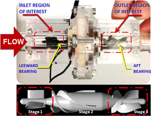
Transparent replica of the HeartMate II and schematic of visualization area
FIGURE 2.
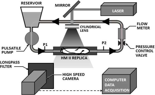
Transparent replica of HeartMate II inserted into simplified circulatory simulator, illuminated by laser sheet.
The regions of interest for visualization were centered at the upstream and downstream bearings (indicated in FIGURE 1), encompassing the upstream and downstream stator blades. The flow field was illuminated with a laser sheet (approximately 1 mm thick) using a diode-pumped solid-state laser (532 nm wavelength, DPSSL-1000), created by cylindrical lens (5 mm diameter, 3.7 mm focal length) in series with a convex lens (5 mm focal length). Background glare was attenuated using an optical longpass filter (550 nm, FGL550s, Thorlabs) providing excellent contrast of the fluorescent particles. Video was acquired using a high speed CMOS camera (Fastcam SA4, Photron USA, Inc.) at two different frame rates, 125 fps and 3000 fps. The experimental matrix encompassed three average flow rates: 4.5 lpm (nominal), 3.0 lpm (low), and 6.0 lpm (high) with the rotor speed maintained at 9,000 rpm. For each of these average flow rates, pulsatile conditions were also visualized in which the flow rate was modulated by approximately 50% of the average flow, i.e. 2.0–6.8 lpm (nominal), 1.6–4.3 lpm (low), and 3.0–9.0 lpm (high). This corresponded to a pulsatility index (PI) of approximately 1.0.20
RESULTS
The flow fields in the upstream and downstream bearing regions exhibited markedly different characteristics. These observations are summarized below for the conditions studied.
Steady State Flow
The path lines in the region of the upstream bearing were observed to be generally stable, well attached, and coherent at the nominal steady-state flow condition (4.5 lpm at 9000 rpm). Figure 3a provides a representative video frame within a visualization plane approximately 2.6 mm anterior of the centerline (1 mm along the span on the blade.) When the flow rate was reduced below 3.8 lpm (9000 rpm, 68 mmHg), a transition in the character of the flow field was observed wherein toroidal vortices appeared between the trailing edge of the upstream stay vane and the leading edge of the impeller, encompassing the front bearing. This is illustrated in Figure 3b for a flow rate of 3.0 lpm (9000 rpm, 72 mmHg), which was also representative of the pathlines observed between 1.0 and 3.8 lpm. As the flow was reduced below 2.0 lpm, the vortex was observed to migrate further upstream within the bladed region of the stator. The path lines in aft stator region were observed to be chaotic for all conditions studied, with virtually indistinguishable differences between 1.0 and 6.0 lpm.
FIGURE 3.
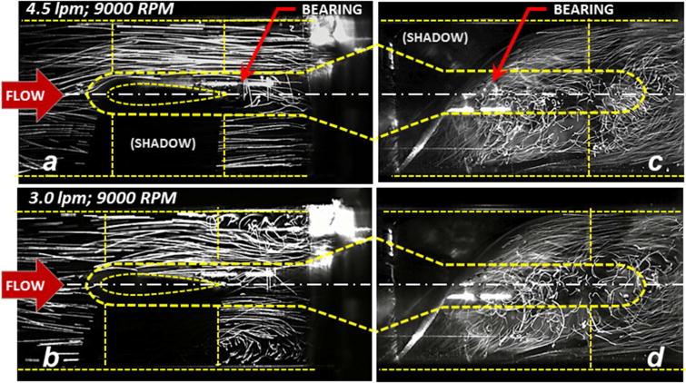
Fluorescent particle pathlines within the upstream and downstream sections of the pump (inset) under steady conditions. At the nominal flow rate of 4.5 lpm the pathlines near the upstream bearing (a) are generally aligned and coherent. Below 3.8 lpm, secondary flow disturbances become evident (b) shown here for 3.0 lpm. Pathlines in the aft stator (c) and (d) are consistently chaotic for all flow rates studied (from 1.0 to 6.0 lpm.)
Pulsatile Flow
Activation of the in-series pneumatic pump introduced an approximately sinusoidal modulation of the volumetric flow rate and differential pressure. Representative waveforms are shown in Figure 4a. To evaluate the influence of pulsatility, the characteristics of the flow field were assessed in terms of the instantaneous flow rate (Q) and rate of change of flow rate (dQ/dt) as reported previously by Shu et al.21 (See Figure 4b.) In general, the stability of the flow field in the upstream bearing region was observed to vacillate between two states, designated as (I) streamlined flow and (II) disturbed flow, closely resembling the high-flow and low-flow steady-state conditions reported previously in Figures 3a and b. By observing the video recordings frame-by-frame, it was possible to identify the approximate point in the cardiac cycle at which the flow field transitioned between these two states — indicated by an open circle in Figure 4b. It was found that the transition between coherent to disturbed flow was a function of both Q and dQ/dt. During ventricular systole, in which the flow was accelerating (dQ/dt>0), the transition point occurred at a lower instantaneous flow rate than when the flow was decelerating (dQ/dt<0). This was most apparent for the nominal flow case (4.5 lpm average), for which approximately 1/3 of the cardiac cycle was observed to be chaotic. Figure 5 (top) provides representative video frames for the accelerating and decelerating flow at the same instantaneous flow of 4.5 lpm (indicated by closed circles in Figure 4b.)
FIGURE 4.
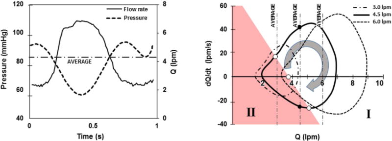
(a) Representative hemodynamics for pulsatile condition, shown here for 4.5 lpm average flow. (b) Same data plotted in terms of acceleration (dQ/dt) versus flow (Q) for one cardiac cycle, at three average hemodynamic conditions. Shaded region (II) indicates conditions wherein disturbed flow was observed in the inlet stator region.
FIGURE 5.
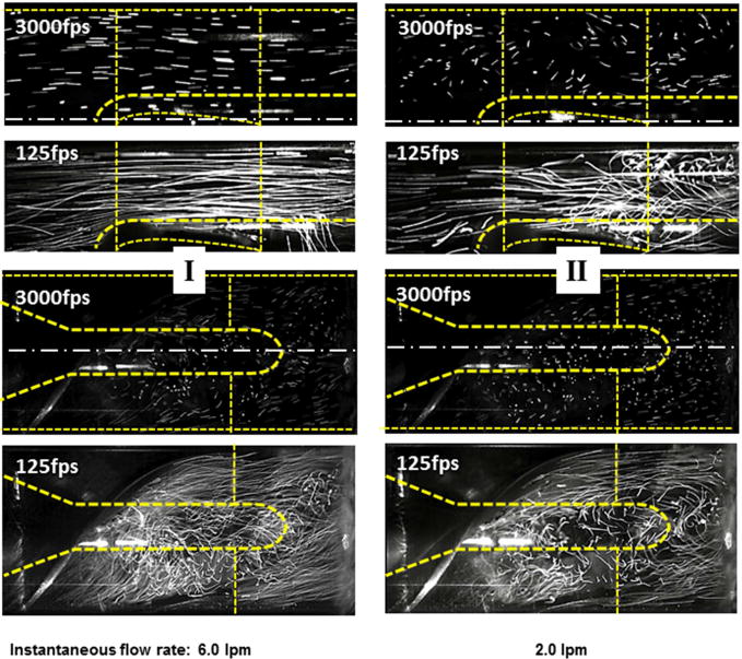
Unsteady (pulsatile) hemodynamic conditions for average flow of 4.5 lpm. Left panel: representative flow fields for the accelerating phase of the cardiac cycle (region I in Figure 4); right panel: corresponding flow field for the decelerating phase (region II.)
The low-flow condition (3.0 lpm average) exhibited chaotic pathlines for approximately 1/2 of the cardiac cycle. At an average flow of 2.0 lpm (not shown), the flow was disturbed for the majority of the cardiac cycle but exhibited a brief period of stable flow during the accelerating portion of the cycle. Conversely, the high flow case (6.0 lpm average) exhibited a brief period of unstable flow during the decelerating portion of the cycle. In all cases, the initial wave of acceleration appeared to displace the vortex structures, washing them downstream. The pathlines in the stator region were highly chaotic throughout the cardiac cycle of all hemodynamic conditions studied. (See Figure 5, bottom panels.) High speed videography (3000 fps) revealed the same general behavior but made it possible to observe the trajectory of individual particles. The latter results are best appreciated in video format, which is provided in the supplemental materials. Under low flow conditions, it was observed that particles were commonly trapped within recirculation bubbles and drawn antegrade along the nose cone causing repeated contact with the bearing surface. In the stator region, for all hemodynamic conditions, the particle path lines exhibited large swirling trajectories. Various coherent structures were periodically observed rotating both clockwise and counterclockwise, at times reversing direction during the cardiac cycle.
DISCUSSION
Despite great advances in the development and utilization of continuous flow ventricular assist devices cfVADs, the incidence of device-related thrombosis remains high.10, 11, 22–25 The problem is understandably multi-factorial and complex.10, 26 Known contributing factors can be categorized as relating to the design of the device, intrinsic properties of the patient’s blood, anti-coagulation strategy, and hemodynamics. More recently, variations in pump implant techniques, influencing the inflow cannula positioning within the left ventricle, have been shown to be related to the incidence of pump thrombosis.27
Practice patterns can also modify the operating conditions of the pump. This was most relevant as reported by several investigators who have recommended operating the HeartMate II at a lower RPM and flow range in an attempt to encourage opening of the aortic valve prevent the development of aortic insufficiency.28 This has the effect of reducing flow across the inflow bearing and also introducing variable amounts of pulsatility as the native ventricle contributes more to the total cardiac output. Until recently, the encouragement of myocardial recovery on an LVAD has not been acknowledged as a risk factor for pump thrombosis. However, in a recent report, pump thrombosis has been noted in association with operating the pump at a lower RPM during the weaning phase of the HeartMate II in a myocardial recovery trial (REmission from Stage D Heart Failure (RESTAGE-HF).29 Finally, one of the most disconcerting complications seen in continuous flow LVAD recipients is chronic gastrointestinal bleeding, which often results in withholding anticoagulation.30 This practice may also have implications for pump thrombosis under circumstances where flow patterns across the pump bearing are not optimized.
Because of the many factors contributing to pump thrombosis, it is virtually impossible to consider all combinations, variations, and permutations in pre-clinical or clinical trials. Therefore, flow visualization studies such as those presented here might serve to interpolate (and possibly extrapolate) the relationships observed clinically. These experiments are not intended as a substitute for formal verification and validation, but as a supplementary tool to gain insight to the internal hemodynamics as influenced by flow rate and pulsatility. This study employed flow visualization techniques reported previously19, 31–33 that provide only a qualitative assessment of the flow fields. Although more sophisticated and quantitative methods are available, we found that a great deal of insight was provided by direct observation of the tracer pathlines. Additional limitations of the protocol should be acknowledged, such as the possible disparity in hemorheology of the blood analog fluid versus whole human blood, and the use of neutrally-buoyant microspheres to visualize path lines of the flow. However it is not likely that errors introduced by these approximations would alter the conclusions presented here.
It is well known that rotodynamic pumps, such as the axial-flow pump studied here, are designed to operate at one specific, steady-state, “best efficiency” point, defined in terms of pressure, flow, and impeller speed. For example, the inflow angle of the impeller blade is designed to match the incipient flow angle at one particular combination of flow and impeller speed. This is rarely the case in practice: owing to the variability of patient size, volume status, afterload, etc. Further deviation from the ideal operating point is caused by the pulsatile contribution of the native heart. Nevertheless, it is desirable to maintain blood flow within the device that is streamlined, absent of stagnation or recirculation regions to minimize the exposure of blood elements to the artificial surfaces and non-physiological shear. From the perspective of the end-user, this is particularly difficult to achieve consistently, as the internal fluid dynamics are neither visible nor measurable. This study therefore aimed to provide some insight to the inter relationship of the observable variables, namely flow rate, pump speed and pulsatility with the flow stability within the device. Specifically, by reference to the flow-acceleration loops of Figure 4, it is possible to intuit the proportion of the cardiac cycle in which the flow is laminar versus disturbed. With minor modifications to the VAD controller, such loops could readily be displayed on a monitor screen.
It was not surprising that unstable, disturbed flow was exhibited at 3.0 lpm which is below the typical use of this device. However it was elucidating that under nominal conditions of 4.5 lpm average output, the flow field resembled 3.0 lpm for approximately one third of the cardiac cycle. Under steady conditions, the approximate breakpoint below which vortices began to appear was 3.8 lpm. But under pulsatile conditions, this breakpoint was dependent on the degree of acceleration or deceleration of the flow: lower during systole and greater during diastole.
This study was not intended to be a definitive nor exhaustive analysis of all possible combinations of pump speed, pressure rise, flow rate, and pulsatility. However the results reported here may be translated to a wide range of conditions through the use of non-dimensional analysis. For steady state flow, Wu et al.31 illustrated that the number of independent variables may be reduced to two
where H and Q are the pressure head and flow rate respectively, R is the radius of the pump impeller, A is the flow discharge area, Ω is the rotational speed of the impeller and g is the acceleration due to gravity. Not only does this simplify the experimental matrix, but also the extrapolation of these results to other combinations of flow rate, pressure head, and speed.
When the hemodynamics are pulsatile, additional independent variables are introduced that can affect the flow field including heart rate, stroke volume and contractility. We previously demonstrated that these independent factors can be simplified by also considering the acceleration or rate of change of flow rate, dQ/dt, or more generally, the first derivative of the flow coefficient, dΦ/dt.21 Therefore, all possible combinations of unsteady hemodynamic conditions can be described by two variables, depicted on the plane. For example, the transition point for found to be Φ = 0.08 for steady-state flow, whereas the transition occurs at a higher instantaneous value when the flow is decelerating (e.g. Φ = 0.12 when dΦ/dt = −1.53×10⁻⁷). And conversely, acceleration of the flow tends to provide a stabilizing effect, allowing a lower instantaneous flow rate that is free from upstream vortices.
Despite the above simplifications, the translation to clinical practice is not entirely obvious. In particular, it is unknown what degree (percentage) of chaotic flow is tolerable. This ambiguity is further confounded by the coagulability of the patient’s blood. Furthermore, the transition from streamlined to unstable to flow is not entirely abrupt.
On the other hand, these studies clearly illustrated that excessively low flow is more precarious than high flow. Extremely high flow (and impeller speed) is also undesirable due to shear stress on the formed blood elements,19 although the present investigation did not detect any observable high-flow transition in the stability of the flow within range studied.
The upstream bearing is known to be particularly vulnerable to thrombosis,11 therefore it is reasonable to believe that sustained vortical flow, causing repeated cell contact with the bearing, and extending the dwell time in this region should be avoided. The fact that unstable flow persists in the aft stator for all conditions is also disconcerting. However, it reasonable to surmise that platelet activation and/or agonist generation produced in the downstream vortices are washed out of the pump, whereas those occurring upstream would be more problematic. These hypotheses warrant further investigation and are the topic of ongoing numerical simulation.
Conclusion
Flow patterns in an axial flow VAD observed in-vitro by high speed flow visualization revealed flow conditions under which potentially pro-thrombotic, chaotic flow features may occur. Under pulsatile conditions caused by the contribution native heart, disturbed flow patterns within the VAD depends on both average flow and pulsatility. Therefore, streamlines that are stable at a specified flow rate under steady-state conditions may become chaotic under pulsatile conditions during the diastolic portion of the cardiac cycle. Translation of these results to clinical practice may be simplified through the use of non-dimensional indices, however future research is necessary to develop definitive guidelines, particularly in situations where increased pulsatility may not be desirable in a pump that was designed to operate optimally under continuous flow conditions.
Supplementary Material
Acknowledgments
This work by supported by R01 HL089456
Glossary of abbreviations
- VAD
ventricular assist devices
- LVAD
left ventricular assist devices
- LV
left ventricle
Footnotes
Publisher's Disclaimer: This is a PDF file of an unedited manuscript that has been accepted for publication. As a service to our customers we are providing this early version of the manuscript. The manuscript will undergo copyediting, typesetting, and review of the resulting proof before it is published in its final citable form. Please note that during the production process errors may be discovered which could affect the content, and all legal disclaimers that apply to the journal pertain.
Disclosures: Authors have no disclosures with regard to commercial support.
References
- 1.Anand J, Singh SK, Hernández R, et al. Continuous-flow ventricular assist device exchange is safe and effective in prolonging support time in patients with end-stage heart failure. The Journal of Thoracic and Cardiovascular Surgery. 2014;149:267–278.e261. doi: 10.1016/j.jtcvs.2014.08.054. [DOI] [PubMed] [Google Scholar]
- 2.Frazier OH. Mechanical circulatory assist device development at the Texas Heart Institute: A personal perspective. The Journal of Thoracic and Cardiovascular Surgery. 2014;147:1738–1744. doi: 10.1016/j.jtcvs.2014.04.019. [DOI] [PubMed] [Google Scholar]
- 3.Jung B, Müller C, Buchenberg W, et al. Investigation of hemodynamics in an in vitro system simulating left ventricular support through the right subclavian artery using 4-dimensional flow magnetic resonance imaging. The Journal of Thoracic and Cardiovascular Surgery. 2015 doi: 10.1016/j.jtcvs.2015.02.048. [DOI] [PubMed] [Google Scholar]
- 4.Karimova A, Pockett CR, Lasuen N, et al. Right ventricular dysfunction in children supported with pulsatile ventricular assist devices. The Journal of Thoracic and Cardiovascular Surgery. 2013;147:1691–1697.e1691. doi: 10.1016/j.jtcvs.2013.11.012. [DOI] [PubMed] [Google Scholar]
- 5.Kwon MH, Zhang JQ, Schaenman JM, et al. Characterization of ventricular assist device– mediated sensitization in the bridge-to-heart-transplantation patient. The Journal of Thoracic and Cardiovascular Surgery. 2015;149:1161–1166. doi: 10.1016/j.jtcvs.2015.01.003. [DOI] [PMC free article] [PubMed] [Google Scholar]
- 6.Rosengart TK. The 1,000th VAD, the great rivalry, and the grand experiment of the Texas Medical Center. The Journal of Thoracic and Cardiovascular Surgery. 2014;147:1745–1747. doi: 10.1016/j.jtcvs.2014.02.040. [DOI] [PubMed] [Google Scholar]
- 7.Taghavi S, Jayarajan SN, Komaroff E, Mangi AA. Continuous flow left ventricular assist device technology has influenced wait times and affected donor allocation in cardiac transplantation. The Journal of Thoracic and Cardiovascular Surgery. 2014;147:1966–1971.e1961. doi: 10.1016/j.jtcvs.2014.02.001. [DOI] [PubMed] [Google Scholar]
- 8.Schoephoerster RT, Chandran KB. Velocity and turbulence measurements past mitrial valve prostheses in a model left ventricle. Journal of biomechanics. 1991;24:549–562. doi: 10.1016/0021-9290(91)90288-x. [DOI] [PubMed] [Google Scholar]
- 9.Bluestein D, Rambod E, Gharib M. Vortex Shedding as a Mechanism for Free Emboli Formation in Mechanical Heart Valves. Journal of Biomechanical Engineering. 1999;122:125–134. doi: 10.1115/1.429634. [DOI] [PubMed] [Google Scholar]
- 10.Kirklin JK, Naftel DC, Kormos RL, et al. Interagency Registry for Mechanically Assisted Circulatory Support (INTERMACS) analysis of pump thrombosis in the HeartMate II left ventricular assist device. The Journal of Heart and Lung Transplantation. 2014;33:12–22. doi: 10.1016/j.healun.2013.11.001. [DOI] [PubMed] [Google Scholar]
- 11.Starling RC, Moazami N, Silvestry SC, et al. Unexpected Abrupt Increase in Left Ventricular Assist Device Thrombosis. New England Journal of Medicine. 2014;370:33–40. doi: 10.1056/NEJMoa1313385. [DOI] [PubMed] [Google Scholar]
- 12.Mehra MR, Stewart GC, Uber PA. The vexing problem of thrombosis in long-term mechanical circulatory support. The Journal of Heart and Lung Transplantation. 2014;33:1–11. doi: 10.1016/j.healun.2013.12.002. [DOI] [PubMed] [Google Scholar]
- 13.Anand J, Singh SK, Hernandez R, et al. Continuous-flow ventricular assist device exchange is safe and effective in prolonging support time in patients with end-stage heart failure. J Thorac Cardiovasc Surg. 2014;149:267–275. doi: 10.1016/j.jtcvs.2014.08.054. 278 e261. [DOI] [PubMed] [Google Scholar]
- 14.Timek TA, Hooker RL, Khaghani A, Merhi W. Hybrid approach to HeartMate II left ventricular assist device exchange. J Thorac Cardiovasc Surg. 2013;145:878–880. doi: 10.1016/j.jtcvs.2012.09.076. [DOI] [PubMed] [Google Scholar]
- 15.Levin AP, Uriel N, Takayama H, et al. Device exchange in HeartMate II recipients: long-term outcomes and risk of thrombosis recurrence. Asaio J. 2015;61:144–149. doi: 10.1097/MAT.0000000000000170. [DOI] [PubMed] [Google Scholar]
- 16.Ota T, Yerebakan H, Akashi H, et al. Continuous-flow left ventricular assist device exchange: clinical outcomes. J Heart Lung Transplant. 2014;33:65–70. doi: 10.1016/j.healun.2013.07.003. [DOI] [PubMed] [Google Scholar]
- 17.Backes D, van den Bergh WM, van Duijn AL, Lahpor JR, van Dijk D, Slooter AJ. Cerebrovascular complications of left ventricular assist devices. Eur J Cardiothorac Surg. 2012;42:612–620. doi: 10.1093/ejcts/ezs320. [DOI] [PubMed] [Google Scholar]
- 18.de Biasi AR, Manning KB, Salemi A. Science for surgeons: Understanding pump thrombogenesis in continuous-flow left ventricular assist devices. The Journal of Thoracic and Cardiovascular Surgery. 2014;149:667–673. doi: 10.1016/j.jtcvs.2014.11.041. [DOI] [PubMed] [Google Scholar]
- 19.Wu ZJ, Gottlieb RK, Burgreen GW, et al. Investigation of fluid dynamics within a miniature mixed flow blood pump. Experiments in Fluids. 2001;31:615–629. [Google Scholar]
- 20.Seongjin C, Antaki JF, Boston JR, Thomas D. A sensorless approach to control of a turbodynamic left ventricular assist system. Control Systems Technology, IEEE Transactions on. 2001;9:473–482. [Google Scholar]
- 21.Shu F, Vandenberghe S, Antaki JF. The Importance of dQ/dt on the Flow Field in a Turbodynamic Pump With Pulsatile Flow. Artificial Organs. 2009;33:757–762. doi: 10.1111/j.1525-1594.2009.00849.x. [DOI] [PMC free article] [PubMed] [Google Scholar]
- 22.Boyle AJ, Russell SD, Teuteberg JJ, et al. Low Thromboembolism and Pump Thrombosis With the HeartMate II Left Ventricular Assist Device: Analysis of Outpatient Anti-coagulation. The Journal of Heart and Lung Transplantation. 2009;28:881–887. doi: 10.1016/j.healun.2009.05.018. [DOI] [PubMed] [Google Scholar]
- 23.Meyer AL, Kuehn C, Weidemann J, et al. Thrombus formation in a HeartMate II left ventricular assist device. The Journal of Thoracic and Cardiovascular Surgery. 2008;135:203–204. doi: 10.1016/j.jtcvs.2007.08.048. [DOI] [PubMed] [Google Scholar]
- 24.Bhamidipati CM, Ailawadi G, Bergin J, Kern JA. Early thrombus in a HeartMate II™ Left Ventricular Assist Device: A Potential Cause of Hemolysis and Diagnostic Dilemma. The Journal of thoracic and cardiovascular surgery. 2010;140:e7–e8. doi: 10.1016/j.jtcvs.2009.09.046. [DOI] [PMC free article] [PubMed] [Google Scholar]
- 25.Fiore M, James C, Mouton C, et al. Assessment of platelet function with light transmission aggregometry in 24 patients supported with a continuous-flow left ventricular assist device: A single-center experience. The Journal of Thoracic and Cardiovascular Surgery. 2014;148:3119–3125.e3111. doi: 10.1016/j.jtcvs.2014.07.091. [DOI] [PubMed] [Google Scholar]
- 26.Uriel N, Han J, Morrison KA, et al. Device thrombosis in HeartMate II continuous-flow left ventricular assist devices: a multifactorial phenomenon. The Journal of Heart and Lung Transplantation. 2014;33:51–59. doi: 10.1016/j.healun.2013.10.005. [DOI] [PubMed] [Google Scholar]
- 27.Taghavi S, Ward C, Jayarajan SN, Gaughan J, Wilson LM, Mangi AA. Surgical Technique Influences HeartMate II Left Ventricular Assist Device Thrombosis. The Annals of Thoracic Surgery. 2013;96:1259–1265. doi: 10.1016/j.athoracsur.2013.05.081. [DOI] [PubMed] [Google Scholar]
- 28.da Rocha e Silva JG, Meyer AL, Eifert S, Garbade J, Mohr FW, Strüber M. Influence of Aortic Valve Opening in Patients With Aortic Insufficiency After LVAD Implantation. The Journal of Heart and Lung Transplantation. 2014;33:S194–S195. [Google Scholar]
- 29.Hurst TE, Moazami N, Starling RC. Left ventricular assist device thrombosis in the setting of left ventricular recovery. The Journal of Heart and Lung Transplantation. 2014;34:622–623. doi: 10.1016/j.healun.2014.12.019. [DOI] [PubMed] [Google Scholar]
- 30.Lopilato AC, Doligalski CT, Caldeira C. Incidence and Risk Factor Analysis for Gastrointestinal Bleeding and Pump Thrombosis in Left Ventricular Assist Device Recipients. Artificial Organs. 2015:1525–1594. doi: 10.1111/aor.12471. [DOI] [PubMed] [Google Scholar]
- 31.Wu ZJ, Antaki JF, Burgreen GW, Butler KC, Thomas DC, Griffith BP. Fluid Dynamic Characterization of Operating Conditions for Continuous Flow Blood Pumps. ASAIO Journal. 1999;45:442–449. doi: 10.1097/00002480-199909000-00015. [DOI] [PubMed] [Google Scholar]
- 32.Kerrigan JP, Yamazaki K, Meyer RK, et al. High-Resolution Fluorescent Particle-Tracking Flow Visualization within an Intraventricular Axial Flow Left Ventricular Assist Device. Artificial Organs. 1996;20:534–540. [PubMed] [Google Scholar]
- 33.Sato K, Orihashi K, Kurosaki T, et al. Analysis of Flow Patterns in a Ventricular Assist Device: A Comparative Study of Particle Image Velocimetry and Computational Fluid Dynamics. Artificial Organs. 2009;33:352–359. doi: 10.1111/j.1525-1594.2009.00726.x. [DOI] [PubMed] [Google Scholar]
Associated Data
This section collects any data citations, data availability statements, or supplementary materials included in this article.


