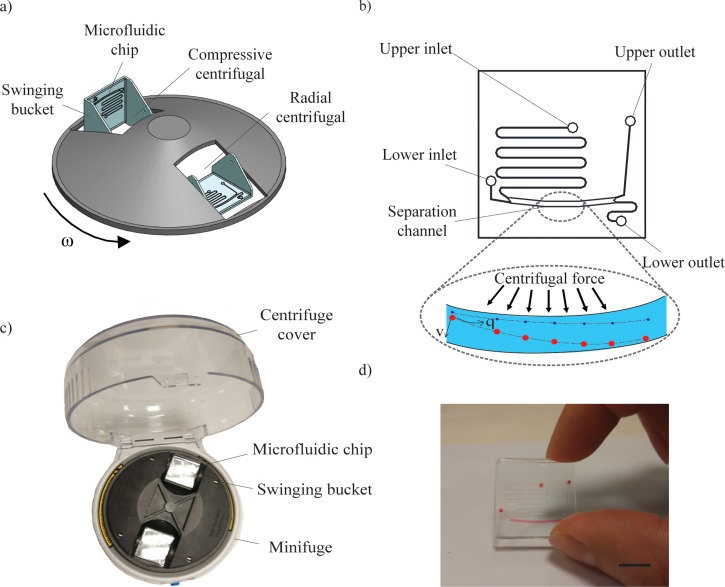
FIG. 1.
Microfluidic chip within a swinging bucket minifuge. (a) Schematic illustration of the centrifugal microfluidic platform driven by radial and compressive centrifugal force. (b) Schematic of the microfluidic chip having two inlets, a separation channel, and two outlets. The separation channel drives particles of different sizes into different outlets. (c) Photograph of actual centrifugal microfluidic system mounted on a minifuge and (d) microfluidic device loaded with red color dye. Scale bar denotes 10 mm.

