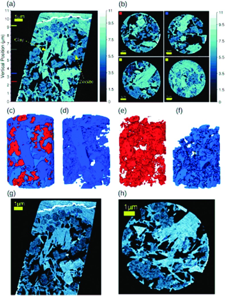
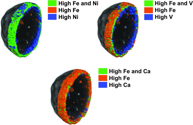
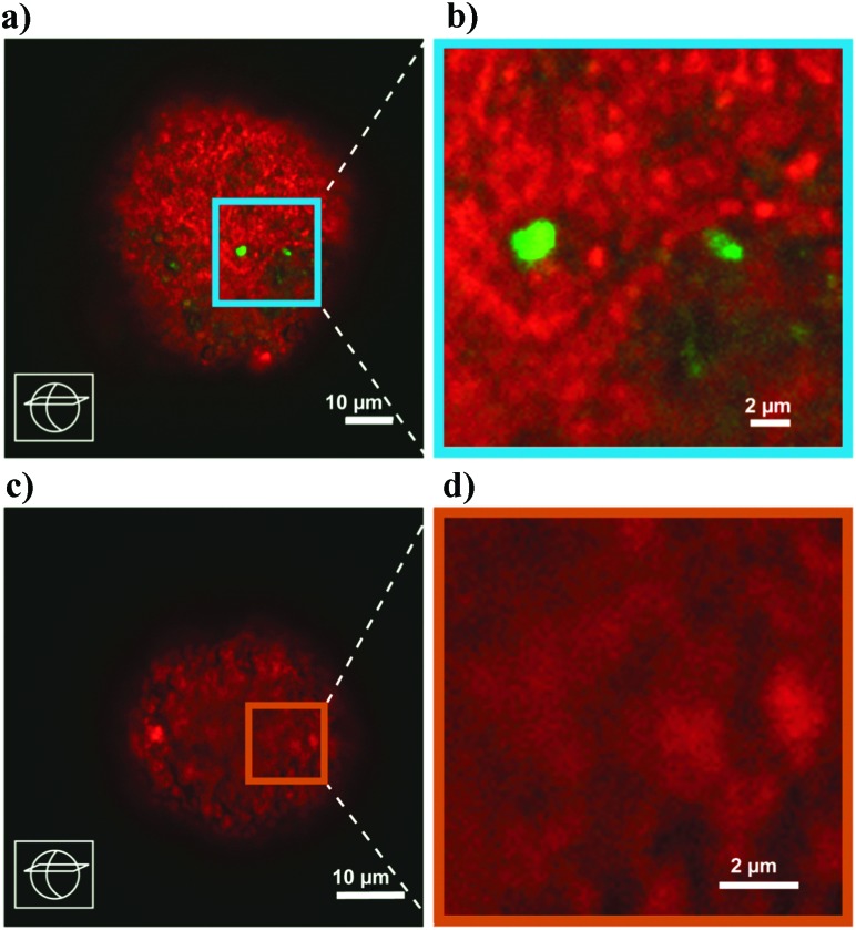
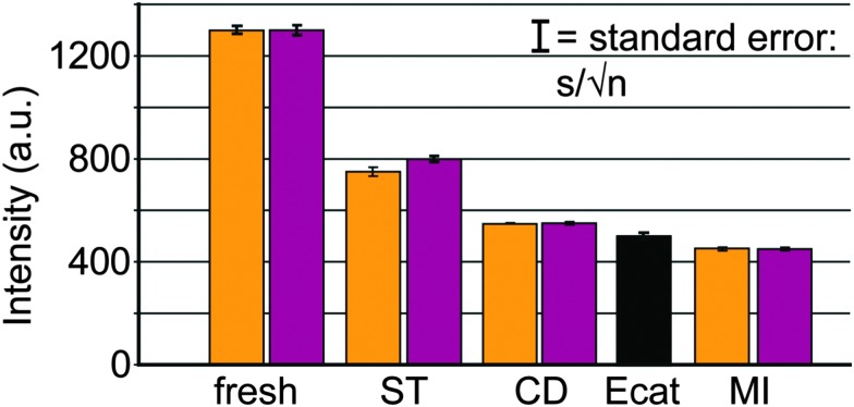
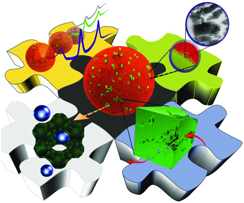
 Fluid catalytic cracking (FCC) is one of the major conversion technologies in the oil refinery industry, and the largest commercial catalytic process that uses zeolite materials.
Abstract
Fluid catalytic cracking (FCC) is one of the major conversion technologies in the oil refinery industry. FCC currently produces the majority of the world's gasoline, as well as an important fraction of propylene for the polymer industry. In this critical review, we give an overview of the latest trends in this field of research. These trends include ways to make it possible to process either very heavy or very light crude oil fractions as well as to co-process biomass-based oxygenates with regular crude oil fractions, and convert these more complex feedstocks in an increasing amount of propylene and diesel-range fuels. After providing some general background of the FCC process, including a short history as well as details on the process, reactor design, chemical reactions involved and catalyst material, we will discuss several trends in FCC catalysis research by focusing on ways to improve the zeolite structure stability, propylene selectivity and the overall catalyst accessibility by (a) the addition of rare earth elements and phosphorus, (b) constructing hierarchical pores systems and (c) the introduction of new zeolite structures. In addition, we present an overview of the state-of-the-art micro-spectroscopy methods for characterizing FCC catalysts at the single particle level. These new characterization tools are able to explain the influence of the harsh FCC processing conditions (e.g. steam) and the presence of various metal poisons (e.g. V, Fe and Ni) in the crude oil feedstocks on the 3-D structure and accessibility of FCC catalyst materials.
1. Introduction
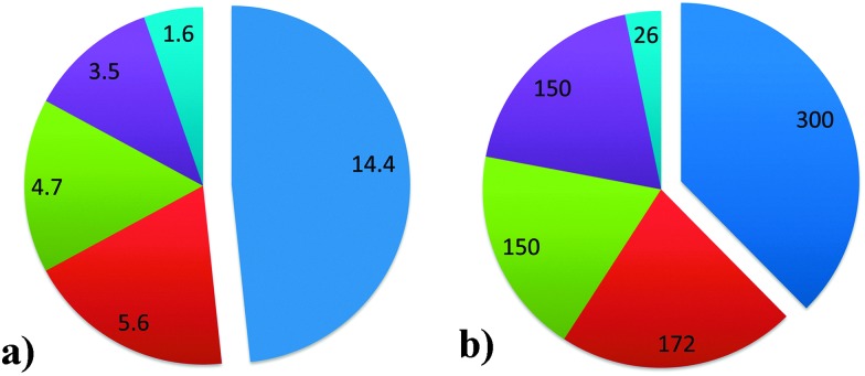
Fluid catalytic cracking (FCC) is one of the major conversion technologies in the oil refinery industry and produces the majority of the world's gasoline. The process is in operation at over 300 out of a total of 646 refineries, as of the beginning of 2014. It is important to note that FCC is not the only conversion process used in oil refineries, as there are also e.g. hydrocracking units. Fig. 1 provides an overview of the different conversion processes in use in oil refineries as of the beginning of 2014, expressed as both the number of barrels of crude oil processed per day and the number of refineries utilizing the processes.1 A number of oil refineries use multiple conversion technologies, and some refineries even have more than one FCC unit. Apart from producing gasoline, the FCC unit is also a major producer of propylene and, to a lesser extent, raw materials for petrochemical processes.
Fig. 1. (a) Installed capacities for the major conversion processes in refineries worldwide, in million barrels per day. (b) Number of refineries in which major conversion processes are installed. Refineries can have more than one technology installed. Data as of 2013, from ref. 1. Color-coding: fluid catalytic cracking (FCC): blue; hydrocracking: red; coking: green; thermal operations: purple; and resid hydrotreating: light blue.
It is estimated that ∼2300 metric tons of FCC catalyst are produced per day,2 or ∼840 000 metric tons per year.
This implies that, on average, approximately 0.16 kg of FCC catalysts are used for the conversion of a barrel of feedstock. This equals about 0.35 lbs per bbl, in units more conventionally used in the field, making use of vacuum gas oil (VGO). Heavier feedstocks, such as resid, require more catalyst material (0.4 lbs per bbl) while lighter feedstocks, such as heavy gas oil (HGO), require less catalyst (∼0.15 lbs per bbl).2 The leading worldwide FCC catalyst producers are W. R. Grace, Albemarle and BASF, while local producers like CCIC in Japan and Sinopec and Petrochina in China have smaller market shares.
In this review article, we will demonstrate that, in spite of the fact that FCC has been practiced for almost 75 years already, the field is still very active and still central in many research activities of both academia and industry. New developments in the availability of feedstocks, such as shale oil and gas and tight oil, the quest to increase the use of renewable resources, as well as changes in the demand for gasoline, result in a desire to change the selectivity of the FCC process. This development has led to a renewed interest in new molecular sieves, zeolites with hierarchical pore structure, and stabilization of the zeolites used in FCC. At the same time a rapid development in analytical tools has recently led to a substantial increase in the fundamental understanding of the integral FCC catalyst particle at sub-micrometer resolution. Reports on new spectroscopic tools used in the analysis of FCC catalyst materials are published in rapid succession. All in all, research in the field of FCC, the grand old lady of zeolite catalysis, is very much alive.
2. Fluid catalytic cracking: some background
2.1. A short history
Commercial production of petroleum dates back to 1859, when Colonel Edwin L. Drake found “rock oil” in Titusville (PA, USA). The initial petroleum products were refined in very simple refineries without conversion capability. At the beginning of the 20th century, the number of cars propelled by an internal combustion engine sharply increased, and a shortage of gasoline developed.
Thermal cracking, in which the unused fractions in the higher boiling range were converted to gasoline-range molecules, was first introduced in 1913, by Burton at Standard Oil of Indiana.3,4 However, the gasoline produced by this process was of relatively poor quality. Additives like tetra-ethyl lead, discovered in the 1920's by Midgley, could improve the “octane number” of gasoline,5 but other solutions were required. The first technical embodiment of catalytic cracking was introduced in 1915, when McAfee at Gulf Refining Company developed a catalyst based on aluminum chloride.6 However, this process was not economically feasible,7 and was abandoned.
In the 1920's, French engineer Houdry experimented with the conversion of lignite to useful products, and found that clay minerals could convert his lignite-based oil to a fuel similar to gasoline.3,8 This was the advent of catalytic cracking as we know it today. Houdry moved to the USA and developed his process with the Socony-Vacuum Oil company (which later became Mobil Oil Company), and eventually the first catalytic cracker operating the Houdry process, which processed 15 000 barrels of petroleum per day, was started up in 1936 in Paulsboro (NJ, USA). The first full-scale commercial plant went on-stream in 1937 at Sun Oil's refinery in Marcus Hook (PA, USA).8 The catalyst was replaced by a synthetic silica-alumina already in the early 1940's, and the process, which produced very high quality fuels, was very quickly developed to produce aviation fuel for the allied war effort in the Second World War. The original Houdry process made use of a fixed bed reactor.
In 1938, a consortium called Catalytic Research Associates (originally Standard Oil of New Jersey, Standard Oil of Indiana, M. W. Kellogg Co., and I. G. Farben) set out to develop a new cracking process.9 At the beginning of the 2nd World War, I. G. Farben was dropped from the Consortium, and Anglo-Iranian Oil Co. Ltd, Royal Dutch-Shell Co., The Texas Co. and Universal Oil Products Co. (UOP) joined. A pilot plant based on a powdered catalyst moving through a pipe coil reactor and a regenerator was built in Baton Rouge (LA, USA). The 100 barrels per day unit was called PECLA-1 (Powdered Experimental Catalyst, Louisiana). In about a year, the system was developed to commercial stage, and mid-1942, the first commercial FCC unit (PCLA-1) was started up.9,10 This system was based on an up-flow reactor and regenerator11 and used a clay-based catalyst.9 It was based on work of Lewis and Gilliland,12 working with Standard Oil Company of New Jersey, who suggested that a low velocity gas flow through a powder might “lift” it enough to cause it to flow in a manner similar to a liquid.13
The system was extremely successful, and with ongoing developments,14 at the end of the war, 34 FCC units were in operation in the USA. PCLA No. 3, which was the second unit at Baton Rouge, was started up in June, 1943. This unit is still in operation today, and is the oldest operating FCC unit, as the PCLA-1 unit was shut down in 1963.
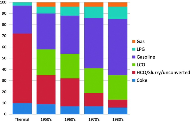
As mentioned before the initial FCC process used clay-based catalysts. Improvements were soon made, and synthetic amorphous SiO2–Al2O3 or SiO2–MgO-based catalysts were developed already in the 1940's.17 The reason for this was an improved selectivity to the desired products,18 as can be observed in Fig. 2 using data from ref. 15 and 16. The graph shows a combined effect of activity increase and selectivity improvement.
Fig. 2. The effect of improving reactor and catalyst technology on the product selectivity for the FCC process for four decades in the 1900's. Color-coding: gas: orange; LPG: light blue; gasoline: purple; LCO: green; HCO/slurry/unconverted: red; and coke: dark blue. Data are obtained from ref. 15 and 16.
In the early 1960's and 1970's, synthetic crystalline microporous aluminosilicates (i.e. zeolites) were invented at the laboratories of Union Carbide and Mobil Oil Corporation. The first of these relevant to FCC was synthetic faujasite (IUPAC structure code FAU19), or zeolite Y (Linde Y), invented by Breck at Union Carbide.20 Zeolite Y in various improved forms has been the main cracking component of FCC catalysts since 1964.21 The initial embodiment was Mg-stabilized, while the currently used rare earth (RE)-stabilized zeolite Y was introduced fairly quickly after that.21 A second zeolite that has found large-scale application in FCC is zeolite ZSM-5 (IUPAC structure code MFI19), which was invented in 1973 by Argauer and Landolt at Mobil Oil Corporation.22 The main application of zeolite ZSM-5 has been in FCC operation targeting an increased propylene yield. Fig. 2 clearly shows that the introduction of zeolite materials in FCC catalyst formulations resulted in a drastic increase in the gasoline yield in the 1970s and 1980s. The books by Venuto and Habib23 and Scherzer24 give good accounts of the history and backgrounds of the FCC process up to the 1980's.
2.2. Process and reactor design
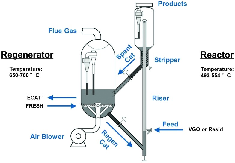
Although a number of different designs exist for the FCC process,25,26 a number of general principles can be described on the basis of Fig. 3. FCC, or at least the cracking reaction, is an endothermic process. The heat required for cracking is produced by sacrificing a small portion of the feedstock, and burning it in the regenerator.
Fig. 3. Schematic depiction of the fluid catalytic cracking (FCC) process, including reactor and regenerator.
Hot catalyst material is combined with pre-heated feedstock at the bottom of the riser reactor. The catalyst-to-oil ratio at the bottom of riser is larger than one, and a typical ratio is 5.5. The temperature at the bottom of the riser is typically in the range of about 550 °C. The reactant mixture expands due to the cracking reaction as gases are formed, and the catalyst/feedstock mixture is rapidly transported up the riser reactor, at speeds approaching 40 m s–1. The typical contact time in a riser is therefore in the order of seconds. At the top of the riser reactor, the temperature has dropped to about 500 °C as catalytic cracking is an endothermic process. The catalyst is separated from the product mixture and stripped of remaining useful product by steam treatment. The products are further refined downstream. The catalyst material, on which a certain amount of carbon, better known as coke, has been deposited during the cracking process, is transported to the regenerator, where the coke is burned off. The catalyst is thus regenerated and re-used continuously. Depending on the exact conditions (such as the oxygen availability), the regenerator temperature can reach up to 760 °C.16
The selectivity to gasoline is in the order of 50% (see also Fig. 2). The catalyst temperature cycles between about 500 °C and about 760 °C, while it is moving at great speed. It is clear that this means the catalyst is exposed to harsh reaction conditions. As a result of this, the catalyst deactivates. A conservative estimate is that a typical FCC catalyst particle has an average lifetime in the order of about 1 month. Since it is not possible in the present process to selectively remove the deactivated catalyst, refiners remove a small portion of the complete inventory of the regenerator at fixed intervals (typically daily), and replace the removed catalyst with fresh catalyst. When this practice is performed for a longer period, a more or less steady state is reached in the catalyst life-time distribution, which is called equilibrium catalyst, or E-cat. Depending on the size of the FCC unit and the operational parameters, catalyst withdrawal rates can be between 1 and 30 tons per day.
2.3. The FCC unit in the oil refinery
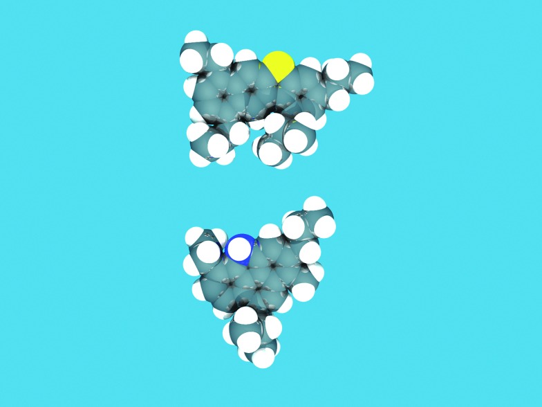
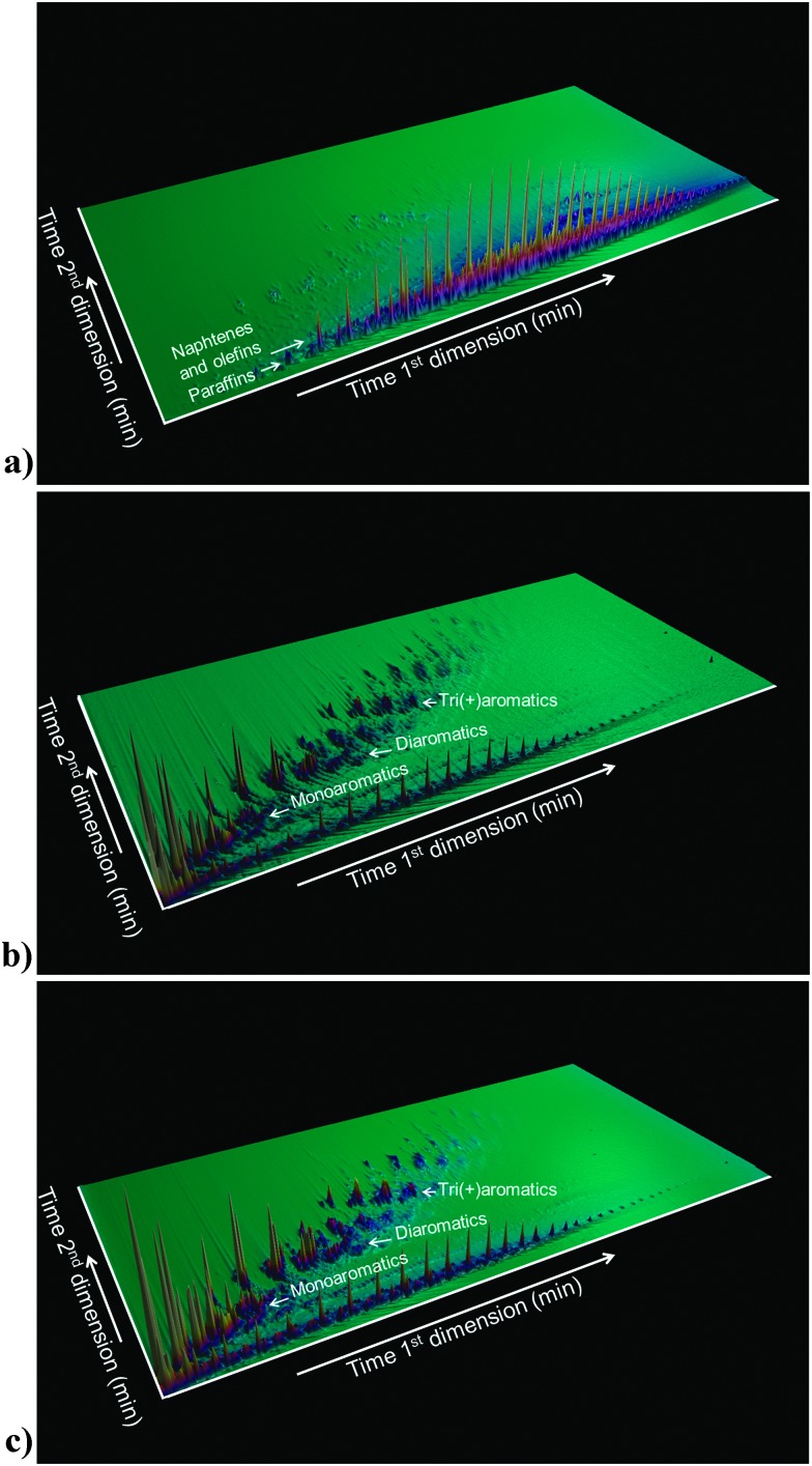
The function of the FCC unit in an oil refinery is to convert heavy gas oil (HGO), vacuum gas oil (VGO) or residue feedstocks into useful products. Fig. 4, based on models by Fu et al. and Ma et al.,27 provides an artist impression of molecules such as could be found in an FCC feedstock, depicting larger aromatic structures with alkyl side-chains, as well as sulfur and nitrogen impurities (oxygen would be present in similar molecules), while Fig. 5a illustrates the complexity of a typical VGO feedstock with a GC × GC plot. When applying a zeolite Y-containing FCC catalyst material the wide variety of molecules present in the VGO feedstock is converted into molecules with on average a lower molecular weight, as illustrated in Fig. 5b, including molecules in the gasoline range (i.e., the 150 °C boiling temperature range). A typical molecule in the gasoline range would be 2,2,3-trimethylpentane (i.e., iso-octane). VGO feedstocks typically boil at 340–540 °C30 while resid has a higher boiling range (>540 °C), and contains multi-layered systems of poly-aromatic rings.
Fig. 4. Typical molecules that could be found in an FCC feedstock, depicting larger aromatic structures with alkyl side-chains, as well as impurities: in this case sulfur (yellow) and nitrogen (blue). Structures based on VGO-molecule cores described in Fu et al. and Ma et al. 27 The structures were sketched in the ADF-builder, and energy-minimized using the built-in UFF force field in ADF.28 The resulting atomic positions were rendered with POV-Ray 3.6.29 .
Fig. 5. (a) GC × GC plot of a typical FCC feedstock (i.e., VGO). (b) GC × GC plot of the products of cracking the VGO in (a), making use of an FCC catalyst with zeolite Y. (c) GC × GC plot of the products of cracking the VGO making use of an FCC catalyst with zeolite Y in the presence of zeolite ZSM-5 as additive.
In addition to multi-aromatic ring structures, both VGO and resid, also contain impurities, such as sulfur and nitrogen, and Ni, Fe and V. These are typically remainders from the plant or animal life forms that originally made up the organic matter that decayed into fossil fuels over millions of years, although they can also originate from the interaction of the oil fractions with rock formations. Interestingly, by comparing the GC × GC plots of Fig. 5b and c one can appreciate the influence of the addition of zeolite ZSM-5 to an FCC catalyst material.
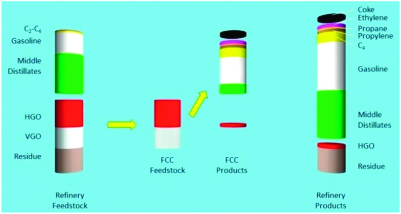
A more schematic way of illustrating the FCC conversion process is shown in Fig. 6.31 Approximately 45% of the original feedstock (i.e., middle distillates, naphtha, and C2–C4-range molecules) can be further processed without conversion e.g. in reforming and isomerization to increase their value, and will likely require some form of hydrotreatment (e.g. HDS) to remove impurities.
Fig. 6. The effect of FCC conversion on total refinery product. Left: Atmospheric distillation frees up about 50% of the feedstock (middle distillates, gasoline and light gases). Heavy gas oil (HGO) and vacuum gas oil (VGO) are converted in the FCC unit. The products from FCC are combined with the initial products from crude distillation in the column on the right. More recent FCC processes will also convert part of the residue. Data from ref. 31.
A major part of the remaining relatively low-value bottom-of-the-barrel fractions (HGO and VGO in this example) are converted to desired products by the actions of the FCC catalyst, in which molecules are cracked to form high-octane rating products. The residue is not converted by the FCC catalyst in this particular example,31 although present day FCC catalyst materials can certainly convert resid, and resid FCC has now become an important process and, consequently, a vast amount of research is directed to focus on resid conversion.
3. The FCC catalyst material
3.1. Structure and composition
The FCC process as described above sets a number of demands for catalyst parameters:16
• Activity, selectivity and accessibility: first of all, the catalytic properties to convert the large feedstock molecules to the desired molecules;
• Attrition resistance: the catalyst particles must be able to withstand the impacts with each other and the unit walls during circulation;
• Hydrothermal stability: the catalyst must be able to withstand the temperature and steam partial pressure in the regenerator;
• Metals tolerance: the catalyst must be able to withstand the actions of poisons in the (heavier) feedstock;
• Coke selectivity: the catalyst must make the minimum amount of coke at high cracking activity, especially when processing heavier feedstocks, such as resids; and
• Fluidizability: the catalyst components must be available in a form that allows fluidization in the regenerator.
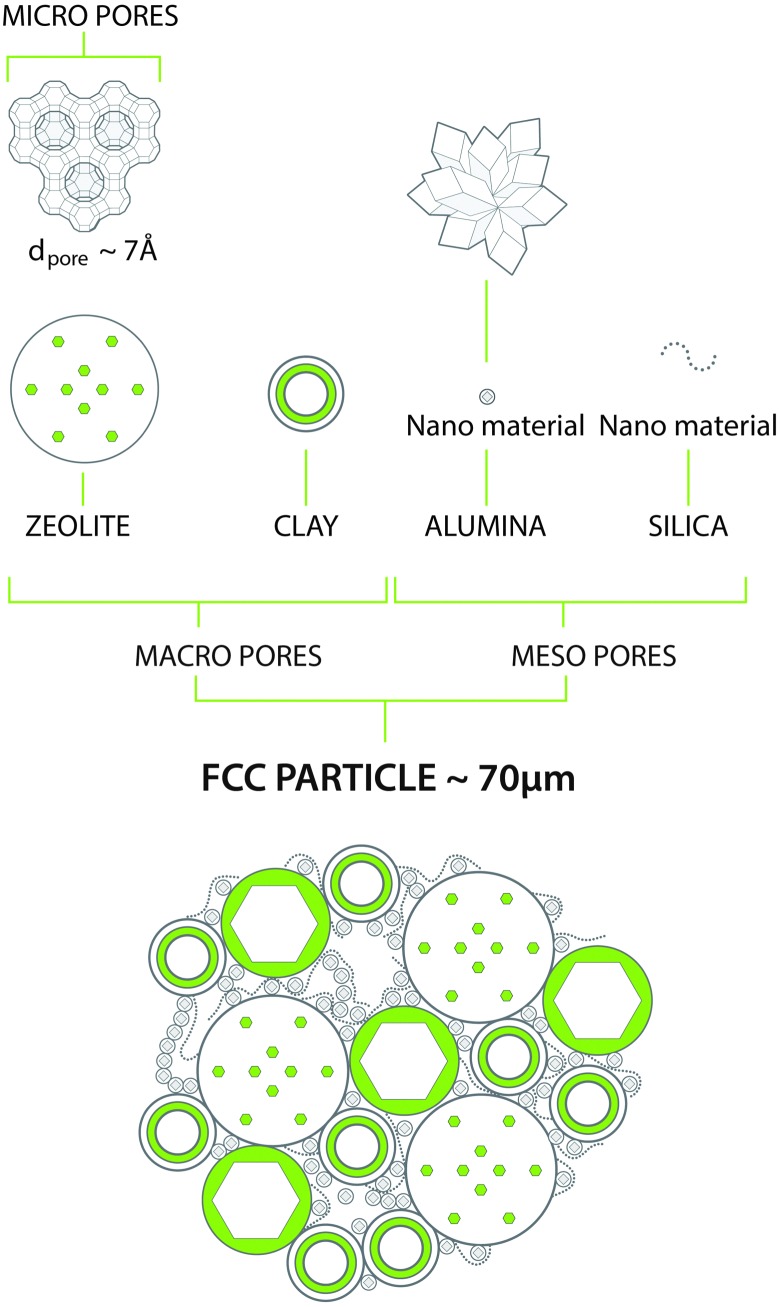
The above demands can be met in a catalyst system that combines a number of components, as depicted in Fig. 7. As described above, the main active component is a zeolite, usually a stabilized form of zeolite Y. This material contains an internal porous structure in which acid sites are present, which can convert larger molecules to the desired gasoline range molecules. Clay is added as filler, but also for heat-capacity reasons. Various alumina and silica sources are used to produce a meso- and macroporous matrix that allows access to, and pre-cracks the larger molecules in the feedstocks. In addition, these components are used to bind the system together. Additional components may comprise specific metal traps for trapping Ni and V. The components are typically mixed in aqueous slurry, and then spray-dried to form more or less uniform spherical particles that can be fluidized in the regenerator.
Fig. 7. Typical chemical and structural composition of a FCC particle. Artwork by RSK Communication.
3.2. Reactions
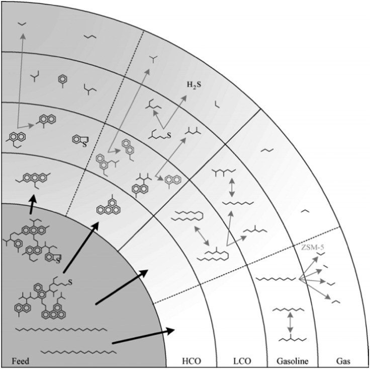
Fig. 8, reproduced from the work of Dupain et al.,32 provides a schematic overview of the reactions occurring in the conversion of FCC feedstocks to gasoline range or gas products. It is clear that the conversion occurs in stages, and gasoline is not the primary reaction product, which should be obvious, since the large molecules in the feedstock cannot enter the (∼7.3 Å) pores of zeolite Y. Rather, the large molecules are pre-cracked in the matrix on their way to the zeolites. The cracking reactions are likely a combination between thermal and catalytic reactions, in which the catalytic reaction becomes more important as the molecules get smaller. The catalytic cracking reaction is acid-catalyzed.
Fig. 8. Consecutive cracking reactions of complex feedstock leading to the final FCC products. (Reproduced from ref. 32 with permission, Copyright Elsevier, 2005).
Acidity can be found both at the surface of matrix particles (for instance, Brønsted acidity at silica-alumina interfaces, or Lewis acidity at Al2O3 surfaces), or in the zeolite. The basic structure for zeolites is a tetrahedrally linked silicate. In some lattice positions, the silicon is replaced by aluminum. Since aluminum is present as a trivalent cation, this induces a local negative charge in the lattice, which can be compensated with a proton to form a Brønsted acid site. Lewis acid sites can be formed when the aluminum sites are coordinatively unsaturated when the framework is damaged (e.g. by steaming).
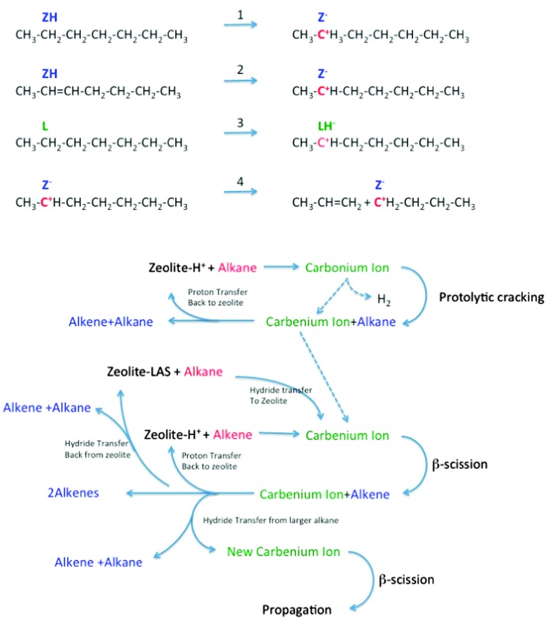
The subject of the cracking mechanism was discussed from the early days of catalytic cracking.33 It is now generally accepted that catalytic cracking involves the formation of carbenium ions.34 As depicted in Fig. 9, there is variety of ways these can be created:35,36
Fig. 9. Reaction network in zeolite-assisted cracking of hydrocarbon molecules. Reaction 1: proton transfer from zeolite Brønsted site to alkane to form carbonium ion. Reaction 2: proton transfer from zeolite to alkene to form carbenium ion. Reaction 3: hydride transfer from alkane to zeolite to form carbenium ion. Reaction 4: Beta scission of a carbenium ion to form a new carbenium ion and an alkene.
(1) Brønsted acid sites can donate a proton to an alkene. This alkene must than have been formed by thermal cracking beforehand. Dupain et al. describe that the initial stages of the FCC process involve mostly thermal (radical) cracking on the outer surface.32
(2) Lewis acid sites can abstract a hydride from an alkane, and the same can occur on strong Brønsted sites (forming dihydrogen).
(3) Alternatively, a Brønsted acid site can donate a proton to an alkane, forming a penta-coordinated carbonium ion. When the carbonium ion cracks protolytically (monomolecular, Haag–Dessau), an alkane and a carbenium ion remain.37
Isomerization reactions can yield branched molecules, in which the tertiary carbenium ions are more stable. The carbenium ions formed in steps 1–3 crack through β-scission, forming a smaller alkene and a smaller carbenium ion. Hydride abstraction from a larger alkane molecule allows the smaller carbenium ion to desorb from the acid site as an alkane, leaving a new larger carbenium ion on the zeolite acid site to propagate the reaction. Alternatively, the carbenium ion can donate the proton back to the acid site, and desorb as an alkene.
Corma et al. 34 conclude that both pathways, involving initial carbenium ion formation on Lewis sites and initial carbonium ion formation on Brønsted sites, occur in parallel.
3.3. FCC catalyst testing
One of the major problems in designing improved FCC catalysts is that it is very difficult to scale down the commercial FCC process with its short residence time and rapid deactivation processes. The feedstocks are complex and contain various impurities that can have a major effect on performance, such as Conradsen carbon, metals like Ni and V, oxygenates, and nitrogen- and sulfur-containing molecules. Resid feedstocks require a different operation than VGO, and diesel- or propylene-selective applications again are completely different.38
Over the years, various more or less standard methods have been developed for testing FCC catalysts. The first was the “MAT”-test, or Micro Activity Test, according to ASTM D-3907. In this test, a small sample of catalyst is tested in fixed bed. Conversion can be influenced by changing the catalyst-to-oil (CTO) ratio. The test has various drawbacks,38 but has nevertheless been very popular over the years. The test contacts the catalyst and feed for prolonged periods, during which deactivation of the FCC catalyst proceeds, and coke- and temperature profiles may develop over the catalyst bed. As a result of the prolonged exposure to feedstock, also the amount of coke deposited on the catalyst material may be unrealistic. The same holds for the observed gas selectivities.
The major drawbacks, concerning contact time and feed vaporization were addressed in various protocols.39,40 Kayser41 developed the so-called ACE (Advanced Cracking Evaluation) units, a catalytic fixed fluid bed system, in which a small catalyst sample (typically about 1 g) is fluidized in a gas stream, and a brief pulse of atomized VGO is passed through the fluidized bed at 538 °C (1000 °F). Another solution capable of handling the heavier feedstock is the Short Contact Time Resid Test, described by Imhof et al. 42 MAT and its refinements (e.g. SCT-MAT and AUTOMAT43) and ACE protocols can show ranking differences amongst each other, but also with pilot plant results.
To overcome this, more realistic simulations or even downscaled versions of the riser reactor, like Pilot Riser Units (PRU), have to be applied. The closest approximation on lab scale may be the Micro-riser simulation based on a coiled reactor developed by Dupain et al.,32 and the Micro-downer developed by Corma et al.,44 a moving bed system with short contact time, which also allows testing with heavier feedstocks.
While FCC catalyst testing is already complicated, the protocol will also have to take into account the deactivation of the catalyst during its lifetime of cracking and regeneration cycles. The deactivation of the catalyst is caused by steaming during the regeneration and assisted by the presence of metals like Ni and V (but also Fe, Na and Ca). Deactivated commercial catalysts may contain thousands of ppms of Ni and V, depending on the operation. Mitchell Impregnation (MI)45 is used to deposit Ni and V on the catalyst particle, usually prior to steaming. The metals are impregnated throughout the catalyst particle, which is maybe (in part) correct for V, but certainly not for Ni. Simple steaming of the catalyst (with or without metals) at increased temperatures mimics the effect of the regenerator in vary crude way.
More realistic procedures mimic the cracking-regeneration cycles, e.g. cyclic propane steaming (CPS),48 in which the catalysts are exposed to multiple cycles of (propane) cracking, stripping and steaming prior to the actual activity tests. A more elaborate deactivation procedure is the cyclic deactivation (CD) procedure,49 in which actual feedstock cracking, depositing metals every cycle, is combined with regeneration for many (up to over 50) cycles to create a more realistic metals profile. Improvements are the two-step CD (2s-CD) and advanced CPS protocols, as described by Psarras et al. 50
3.4. Zeolite framework stabilization
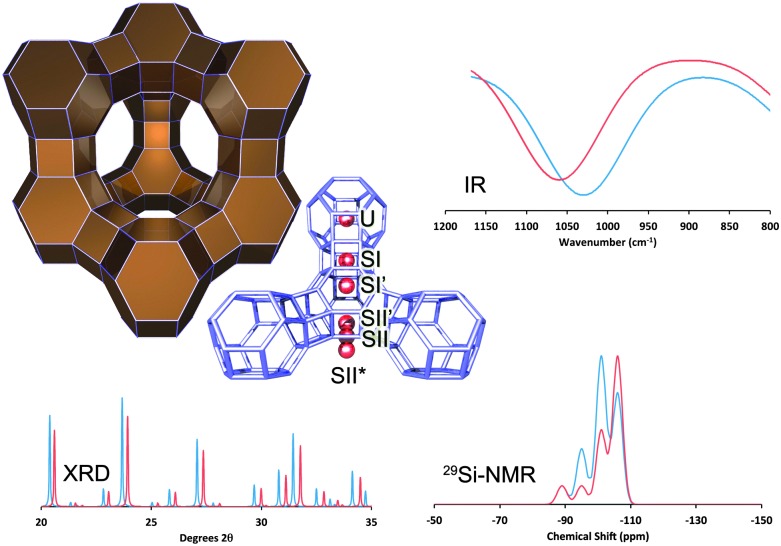
As mentioned above, the main cracking component in FCC catalysts responsible for the production of gasoline-range molecules is zeolite Y.19 The structure of zeolite Y, shown in Fig. 10, has a 3-D pore system, in which pores of ∼7.3 Å connect larger (13 Å in diameter) cages, which are known as the supercages of this zeolite.
Fig. 10. The structure of zeolite Y (Faujasite), with the most relevant ion-exchange sites highlighted. The effect of RE-introduction: XRD: comparing RE-stabilized (blue) with non-stabilized Y-zeolite (red), we observe a shift to lower angles (i.e. larger unit cell size, lower SAR, less dealumination), as well as higher crystallinity in the RE-stabilized material; IR: we observe a shift to lower frequency (lower SAR, less dealumination) for the RE-stabilized form; NMR: we observe larger contributions from Si-species with multiple Al-neighbors (i.e., a lower SAR, less dealumination). All spectra are simulated based on literature data from Roelofsen46 and Scherzer et al. 47 .
The addition of solid acids to the catalyst improves both the conversion as well the product selectivity towards gasoline. The original FCC catalyst contained clay, and later amorphous silica-alumina and silica-magnesia. The advent of zeolite-based catalytic cracking was seen shortly after their discovery at Union Carbide,20,21 in the early 1960's. Zeolite Y combines high surface area/pore volume solid acidity (both Brønsted and Lewis) with sufficient room to allow bimolecular (carbenium ion) cracking. The preparation of the zeolite is relatively simple, no organic Structure Directing Agents (SDAs) or even autoclaves are required. However, the as-prepared zeolite is not very stable towards hydrothermal conditions. The stability can be improved by controlled steaming and washing/leaching cycles (to make the so-called ultra stable Y, or US-Y).
A well-known way to improve the effectiveness of the zeolite (i.e. to retain activity longer) is to exchange part of the counter-ions with rare earth (RE) ions. There is a lot of literature on the effect of RE ions on zeolite stability and reaction characteristics. A large body of work in this area was already performed in the 1970's and 1980's.
For example, Rees et al. 51 show that the exothermic peak in differential thermal analysis, which is interpreted as a collapse of the framework, shifts towards higher temperature for RE-exchanged faujasite versus Na-exchanged faujasite. This framework collapse occurs in the range of 800–1000 °C, so outside of the temperature range relevant for FCC. Nevertheless, the effect is an indication for increased lattice thermal stability.
Flanigen et al. 52 provide an assignment of the IR vibrations observed for zeolite Y. Roelofsen et al. 46 explain that the symmetric stretch vibration at around 790 cm–1 is the most suited to derive the framework silicon-to-aluminum ratio, shortened as SAR, because other IR peaks are more sensitive to the type and amount of cations in the framework, crystallinity, as well as water content. The peak frequency of the IR band at around 790 cm–1 has found to be linearly proportional to the Al/(Al + Si)-ratio.
Rabo et al. 53 describe two IR peaks related to hydroxyl groups in RE-Y. The first peak, at 3640 cm–1, shows strong hydrogen bonding with water, benzene and ammonia, and can thus be interpreted as a Brønsted acid site exposed in the supercage. The other OH-vibration, centered at 3524 cm–1, does not bind with ammonia or benzene, and is thus hidden inside the sodalite cage. Rabo et al. assume these hydroxyls are associated with OH-groups retained between two RE-cations as an electrostatic shield.
Roelofsen et al. 46 investigated the dealumination of zeolite Y with varying loading of RE2O3 (mixed rare earths) with IR, XRD, and 29Si MAS NMR. They find a good correlation between the framework SAR derived from IR and from 29Si MAS NMR. However, the correlation with the SAR derived from the unit cell size using the Breck–Flanigen relation54 does not hold in this case. The unit cell size is significantly larger than would be expected from the Breck–Flanigen relation. This indicates that the unit cell size is not a good indicator for lattice stabilization.
A variety of authors studied the stability of RE-exchanged zeolite Y in the 1960's and 1970's, mostly based on IR-analyses. Scherzer et al. 47 conclude that framework vibrations shift to higher frequencies, and the XRD unit cell size decreases, upon increased severity of the thermal treatment. In both cases there is more or less linear dependence of the effect with the RE-loading. In a subsequent paper, Scherzer and Bass55 look at the OH-stretching region of the same samples. They conclude that bands at 3600 and 3700 cm–1 indicate that the framework is dealuminated. Bands at 3650 and 3600 cm–1 are shown to be acidic (from interaction with ammonia, pyridine, and sodium hydroxide). They also observed a band at 3540 cm–1, which they ascribe to OH groups attached to lanthanum ions, although there also appears to be a framework band in the same IR region.
Fallabella et al. 56 study the effects of using different RE-ions in the ion exchange process of zeolite Y. The introduction of RE cations brought about no significant changes in the structural region of the zeolites. However, in the hydroxyl region, a band ranging from 3530 to 3498 cm–1 was observed.
This band, attributed to OH groups interacting with RE-cations (see also Scherzer and Bass55), is shifted to higher wavenumbers as the ionic radius of the cations increases. This hydroxyl is not acidic (or at least not active in catalysis), as it resides in the sodalite cages. The authors do note a clear effect of the radius of the RE-ion on the acidity as probed with pyridine and lutidine. Pyridine is capable of detecting both Brønsted and Lewis acid sites, whereas lutidine can only interact Brønsted acid sites due to sterical hindrances generated by the methyl groups. In their study, Dysprosium falls outside the plotted correlation, possibly because remaining chloride ions create extra activity.
Van Bokhoven et al. 57 report that high-charge octahedral extra-framework Al in US-Y, as well as La3+ ions in the ion exchange positions in La(x)NaY induce local polarization of the Al-atoms in the lattice. In addition, a long-range effect is observed which causes the T–O–T angles to increase (and thus the unit cell size to increase). The authors thus assume that although the type of ion is different, the origin of the enhanced activity in US-Y and RE-Y is identical. Most authors claim that rare earth elements stabilize the zeolites by moving into the hexagonal prisms (site S-I), and retaining the framework Al by some form of electrostatic interaction. Excess rare earth migrates from the hexagonal prism into the supercage (site S-II), and forms strong Brønsted acid sites in connection with framework Al.
Du et al. 58 claim that the ionic radius of different RE elements has an effect on the stability of the RE-Y zeolite and the framework stability increases with decreasing ionic radius for the set Ho3+, Dy3+, Nd3+, La3+. Ce3+ does not seem to move into the S-I positions, because under the conditions applied by Du et al. the cerium gets oxidized to Ce4+, and forms a larger complex that cannot migrate into the sodalite cages.
Schüßler et al. 59 investigated the nature and location of La-species in faujasite with a combination of techniques, including DFT calculations. In order to make full periodic calculations possible, they selected the rhombohedral primitive cell of faujasite. This reduces the number of framework atoms by a factor of 4, from 576 to 144. The authors find small amounts of [La(OH)]2+ and [La(OH)2]+-species in the S-II sites, but claim the majority of the La3+ is present in the sodalite cages in multinuclear OH-bridged aggregates. The formation of the hydroxylated clusters leads to the formation of Si–OH–Al groups at a distance to the La-clusters. However, the authors claim that isolated La3+ species in the S-II site are also able to polarize secondary and tertiary C–H bonds and thus activate alkanes, and point to these species as responsible for the enhanced activity and hydrogen transfer of RE-exchanged zeolites.
Noda et al. 60 performed a combination of temperature programmed desorption (TPD) of NH3 with DFT cluster calculations. They examined Ba-, Ca-, and La-exchanged zeolite Y and observe an increase in catalytic activity for all ion-exchanged zeolites with the Ba ones producing the lowest activity. They ascribe the formation of stronger acid sites to a removal of OH-sites in the sodalite cages and hexagonal prisms, and strengthening of the supercage-OH sites by a polarization effect induced by the cations.
From the above, it is clear that the presence of RE-cations in the structure provide some form of stabilization, to the extent that more aluminum is retained in the lattice as observed with IR and NMR. XRD unit cell size analysis does not correlate with IR and NMR measurements in the normal way for RE-containing zeolite Y.
The effect of the presence of RE in the lattice on performance is dramatic. Plank et al. 61 already in the early 1960's noted an appreciable increase in activity (more than 100 times as active as amorphous silica-alumina's) when using RE-stabilized Y zeolites, although they compared their materials to amorphous SiO2–Al2O3 and Na–Y. Although the activity increase is desirable, the incorporation of RE also increases the rate of hydrogen transfer, which leads to a less desirable drop in research octane number and olefinicity in the LPG range. Fallabella et al. 62 define a hydrogen transfer (HT) index derived from the ratio of different reaction rate constants in the cracking of cyclohexene, which correlates with the atomic ratio of the RE-ion and the acidity. Lemos et al. 63 studied heptane cracking on RE-exchanged Y-zeolites, and observed mainly paraffinic cracking products. The cracking activity seems to correlate with strong protonic acidity, as derived by reactivity comparison.
4. Improvements in FCC catalyst materials
4.1. General trends
Even though the FCC process has been with us for over 70 years now, the process is still being developed further. Changes in the demand for products, and changes in the feedstock drive constant development. Fletcher64 lists the following challenges for FCC catalysis:
• LCO maximization (i.e. diesel flexibility);
• Petrochemical feedstock maximization (i.e. propylene);
• Flue gas emissions control; and
• Enhanced metals tolerance.
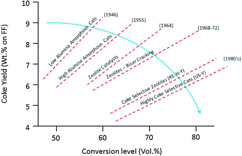
On the one hand, conventional feedstocks are becoming heavier. Resid cracking in FCC gained popularity in the early 1990's, and has gained importance since. Heavier feedstocks imply that larger, more aromatic molecules need to be cracked, which calls for improved accessibility and improved metals tolerance. At the same time, there is a drive to increase activity, but at the same time limit the amount of coke produced to the absolute minimum required for heat balance of the unit. This is a continuous challenge in FCC since the early days, and various improvements have been made over the decades, as illustrated in Fig. 11.
Fig. 11. Effect of subsequent developments in active components on conversion and coke level. Redrawn from ref. 65.
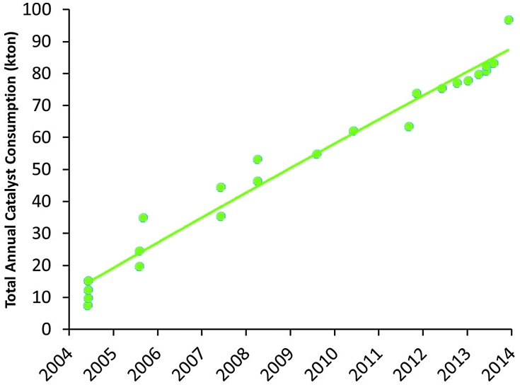
Apart from the conversion of heavier feedstocks, we have recently also seen an increased application of relatively light, paraffinic shale oil as the feedstock to the cracker. So the traditional feedstock of FCC, namely VGO, is replaced more and more by both heavier and lighter feedstocks. At the same time, a similar effect can be observed on the product side. Where (aviation) gasoline was the desired product for the initial FCC units, we have seen an increased demand for propylene over the last two decades. Propylene is the raw material for polypropylene, and the FCC unit can be one of the main sources to form propylene (the other would be steam cracking of naphtha). Propylene can be produced in the FCC unit as a product mostly of secondary cracking of gasoline range molecule, usually by specific additives containing ZSM-5 zeolite. Fig. 12 lists the market size for FCC catalyst specifically targeting propylene production, which has risen from about 10 000 metric tons per year in 2005 to almost 90 000 metric tons of catalyst in 2014.
Fig. 12. Development of the market for propylene-selective FCC catalysts (based on Albemarle market data).
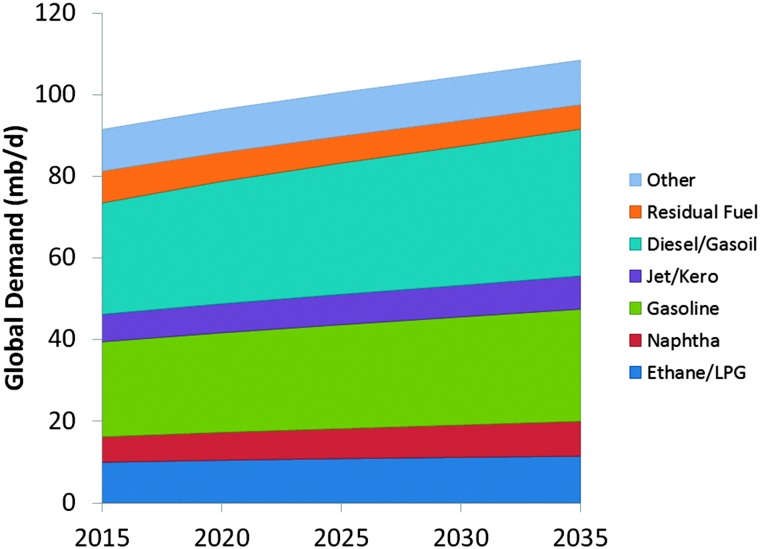
The development of specific FCC-propylene capacity follows the demand for olefins.66 It illustrates the clear expected increase in the propylene demand, which cannot be absorbed by steam cracking alone, and has to come from the FCC unit. On the other hand, as shown in Fig. 13, the world market for gasoline seems to flatten out, and developing countries and even the USA show an increasing demand for diesel as a transportation fuel.
Fig. 13. Projected evolution of the market for selected oil products. Color-coding: ethane/LPG: dark blue; naphtha: red; gasoline: green; jet/kero: purple; diesel/gasoil: blue; residual fuel: orange; other: light blue. Data taken from ref. 67.
The compiled information, based on data from the OPEC World Oil Outlook 2013,67 shows the ratio between gasoline and diesel demand over the next decades is projected to change in favor of diesel. Historically, the USA had a surplus in diesel, and the EU had a surplus in gasoline, which could be traded.68 With the new gasoline/diesel demand ratios predicted for the next decades, this is no longer possible, and this will no doubt have an impact on the desired products from the FCC unit as the main conversion process. The two developments combined require a shift from gasoline as the main product to both higher- and lower-boiling products, which is not possible at the same time.
4.2. Increasing propylene selectivity
Propylene is a minor product (<5% product yield) in normal FCC operation, but selectivity towards propylene can be enhanced by selectively cracking gasoline range molecules. Although increasing the riser temperature, increasing the catalyst-to-oil ratio, and increasing the residence time will increase the propylene yield,69 these options are limited. Corma et al. 70 show for cracking over Y-zeolites, that although propylene yield increases with conversion, propane yield increases faster, so the alkene/alkane ratio decreases at higher conversion. So rather than olefins, coke, dry gas and paraffinic LPG will be produced preferentially through so-called over-cracking. This is because the wide pore system of FAU allows for bimolecular cracking and hydrogen transfer reactions. In order to selectively produce lower olefins, refiners apply additives containing zeolite ZSM-5.66,71,72 These additives, complete FCC catalysts in themselves, usually contain ZSM-5 as the only active zeolite, in loadings of 25–50%. Combination of Y-zeolites and ZSM-5 in one catalyst is also possible, but removes (some) flexibility for the refiner. It is also possible to base the entire conversion on ZSM-5 based catalysts in dedicated processes, such as DCC,73 which operates at higher temperature than the conventional FCC process, and converts heavy feedstocks such as VGO, vacuum resid, or VGO mixed with DeAsphalted Oil, into light olefins or iso-olefins.
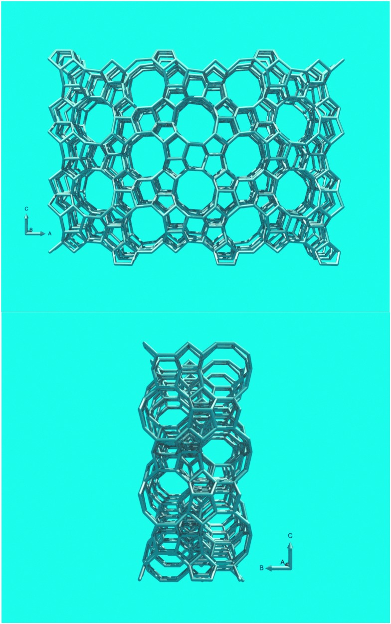
In this review paper, we will exclusively focus on ZSM-5-containing additives. Argauer and Landolt first reported ZSM-5, this structure shown in Fig. 14, as a synthetic molecular sieve in 1972.22 Although Kokotailo et al. solved the structure of ZSM-5 already in 1978,74 recent work has shed new light on this material. Even though zeolite ZSM-5 was first described as a synthetic material, a natural mineral form (named Mutinaite) also exists as it was discovered in Antarctica adjacent to deposits of natural zeolite Beta.75 Zeolite ZSM-5 can be prepared both in the presence and absence of organic SDAs. The typical SDA molecule is tetrapropylamine (TPA), which can be located in the pores of the synthetic material.76 Materials with a silica-to-alumina ratio (i.e., molar SiO2/Al2O3 ratio) up to about 25 can be synthesized without SDA, for higher silica-to-alumina ratios typically an SDA is required. The essentially all-silica form, known as silicalite, has a slightly different structure than the low-SAR material, it has a monoclinic unit cell, whereas the low SAR material crystallizes in an orthorhombic cell. The framework is exactly the same for both phases. The structure of ZSM-5 consists of a 3D pore system circumscribed by 10 T-atoms. The pores are slightly elliptical and have diameters of 5.1–5.6 Å. The structure has a straight 10-MR pore along the [010]-direction, and a zig-zag 10-MR pore along the [100]-direction. The pores intersect, and molecules (of the correct dimensions) can reach any point in the pore system from any other point. ZSM-5 normally crystallizes in lozenge- or coffin-shaped crystals that are frequently twinned.
Fig. 14. (Top) Structure of zeolite ZSM-5, viewed along the 10-MR straight channels. (Bottom) View along the zig-zag channels.
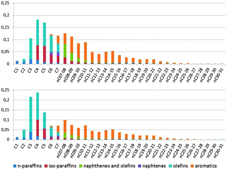
The limited room in the pore system of zeolite ZSM-5 compared to the supercages in zeolite Y implies that it is much more difficult to accommodate the larger bimolecular transition states. As a result, the secondary cracking of gasoline range molecules in ZSM-5 will produce more olefins. This is illustrated in Fig. 15.
Fig. 15. A comparison of the total products from the same runs as depicted in Fig. 4. The graphs are combinations of the GC × GC plot for total liquid product, PIANO analysis of the naphtha fraction, and GC analysis of the gases. Top: Products from a normal cracking run. Bottom: Products with ZSM-5 containing additive added to the catalyst. Color-coding: n-paraffins: dark blue; iso-paraffins: red; naphthenes and olefins: green; naphthenes: purple; olefins: blue; aromatics: orange.
Just like the primary cracking zeolites, also zeolite ZSM-5 is unstable towards the harsh environments of the FCC process. Dealumination by repeated contact with steam in the regenerator dislodges the aluminum from its framework position, thus removing the active acid sites, and in the process destroying the zeolite lattice. Although a partial destruction of the zeolite lattice may improve the diffusion characteristics of the zeolite by creating access to the interior through mesopores, this also creates larger pores, and hence the opportunity for bimolecular cracking.
To increase the stability of zeolite ZSM-5, a treatment with phosphorous is often applied. The trick has been used in ZSM-5 for various applications apart from FCC, such as methanol-to-olefins (MTO) conversion, alkylation, and ethanol dehydration.77 A very recent review on phosphorus promotion of zeolites covers the synthesis, characterization and catalysis aspects of phosphated ZSM-5.78 A variety of phosphorous sources has been used over the years to achieve the desired stabilization. For example, Xue et al. 77 mention organo-phosphorus compounds, such as trimethyl phosphite ((CH3O)3P) and others, and inorganic compounds, such as phosphoric acid (H3PO4) and ammonium phosphates ((NH4)3PO4, (NH4)2HPO4, (NH4)H2PO4) and others. Given the scale of the operation and ease of handling (e.g. by-products), especially the inorganic compounds are of relevance to FCC catalyst manufacturing.
The overall interaction between the phosphorous species and the zeolite lattice seems to be relatively independent of the phosphate source, although the overall effect of the treatment on activity strongly depends on parameters like Al/P ratio, Si/Al ratio, zeolite crystal size, and activation conditions.77,79 When phosphate species are introduced in a way that allows them to enter the pores and react with the bridging hydroxyls of the Si–OH–Al active sites in the zeolites, an adduct forms in which the phosphate ions force the aluminum in an octahedral coordination. This process, which is reversible under treatment with hot water, eliminates the bridging hydroxyls and thus the Brønsted acidity of the zeolite.78 However, when elution with hot water can be avoided during heat treatment, the octahedral Al–POx-species is more stable, and the lattice integrity is maintained to a larger extent then for untreated zeolites. Excess phosphorus used during the treatment will deposit on the external surface of the zeolite ZSM-5 crystals as a polyphosphate. If any aluminum is dislodged during the thermal treatment, it will very likely react with the available phosphate, and form an amorphous aluminophosphate. It should be noted that the ZSM-5-containing additive will generally also contain an alumina binder, which will react with excess phosphate to form an aluminophosphate species that may be beneficial for binding the system.
The effect of the treatment with phosphate on macroscopically observable parameters is
(1) Enhanced stability of the zeolite lattice;
(2) A decrease in the formation of bulky isomers;
(3) Formation of increased amounts of lights olefins in FCC, but also in MTO and ethanol dehydration; and
(4) A decrease in coke formation.
In view of the mechanistic relations described above, the latter two seem to hint at decreased hydrogen transfer, and the second seems to indicate decreased room in the lattice for the formation of bulky intermediates.
The phosphate treatment usually involves impregnation of solutions of phosphate sources, typically H3PO4, or the less acidic ammonium phosphates, followed by drying (70–120 °C) and calcination (450–650 °C) for 1 to 6 h. Although generally the catalysts will be exposed to steam after they were stabilized, some authors describe phosphate treatment after initial steaming. This may lead to the formation of extra-framework aluminum (EFAL) and hydroxyl nests, and dislodged aluminum still partially connected to the lattice.
Various characterization techniques have been used to study phosphated zeolites.78 XPS shows enhanced P-concentration at the surface of larger zeolite crystals, possibly because the initial stage P-species react with surface Si–OH groups before they can enter the pores. The optimal loading for the phosphate treatment seems to be an Al/P-ratio of about unity, although care must be taken to avoid diffusion problem during the impregnation stage. Excess of phosphate will remain on the external surface of the zeolite ZSM-5 crystals. Upon P-treatment, a decrease of porosity/surface area is observed, which is correlating with P-content. A decrease in surface area/porosity can be attributed to pore blockage by P-species, aggregation of zeolite crystals by the action of external polyphosphate, or dealumination.
Although porosity and accessibility are initially decreased, the bridging hydroxyl groups (and thus the acidity) appear to remain available at this stage. The zeolite crystals appear to lose some crystallinity after the calcination treatment following the phosphorous impregnation, but this could be due to scattering of the X-rays by P-species in the pores.
Although the Si/Al ratio as observed with 29Si MAS NMR seems to increase, this may just be caused by changes in the coordination spheres of the Si- or Al-species in the lattice, and not necessarily by removal of the framework Al. Depending on conditions for the calcination, the phosphate species may coordinate to the aluminum, and thus break the Si–OH–Al bridges. Although this would lower the number of strong acid sites, the Al–O–P(OH)3 and Si–OH species formed when this happens may lead to new acid sites, and partially connected Al may form additional Lewis acid sites.
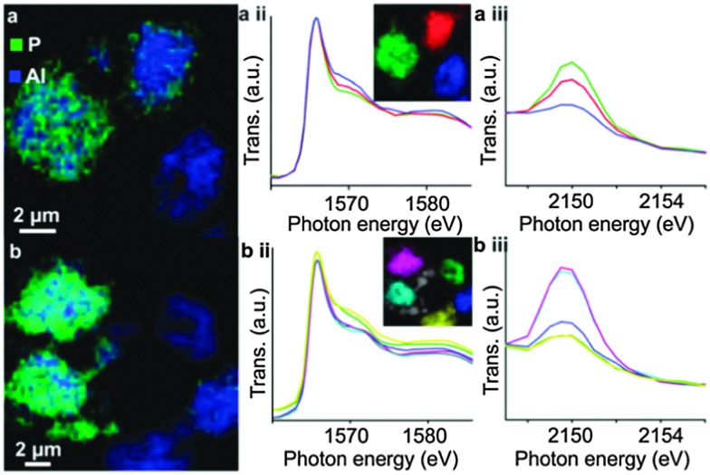
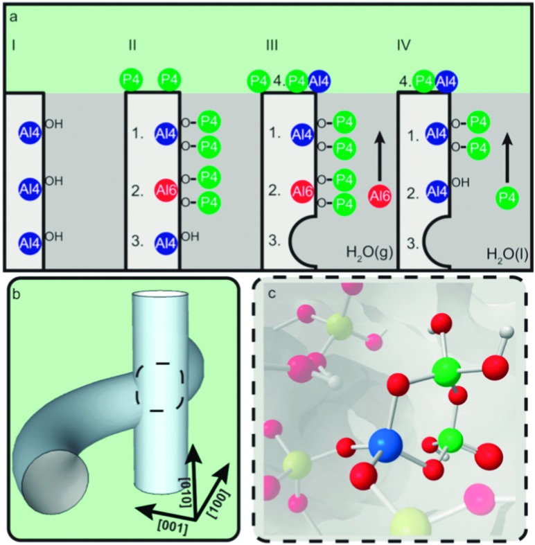
Upon phosphate treatment, the typical resonances for tetrahedral framework Al seem to decrease in 27Al MAS NMR. This does not necessarily mean that the Al is dislodged from its framework position. By using combined spectroscopy and scanning transmission X-ray microscopy (STXM), van der Bij et al. observed that there are two different interactions between the phosphate and aluminum (Fig. 16). Extra-framework aluminum reacts with the P-sources to form an extra-framework crystalline ALPO phase. When there is no EFAL to react with, the P reacts with framework Al, seriously distorting its coordination, but without forming EFAL species. These distorted sites were more or less immune to hydrothermal treatment. Excess phosphate was found on the external surface of the zeolite crystals.
Fig. 16. Chemical maps of phosphate-activated zeolite clusters, constructed from Al and P K-edge spectra stacks for two different samples. Blue color denotes Al, red denotes P, resolution is 60 × 60 nm. (a-ii) and (b-ii) Al K-edge XANES spectra; (a-iii) and (b-iii) P K-Edge XANES spectra, spectra in (ii) and (iii) colored according to the color in the inset. (Reproduced from ref. 80, Copyright PCCP Owner Societies, 2014).
Upon heat treatment, van der Bij et al. observed the formation of stable –(SiO)3–x–Al–(PO)x– type species (see Fig. 17), in other words SAPO species are connected to the framework, but with Al no longer in its original framework position.
Fig. 17. Schematic representation of the effect of phosphate on the stability of ZSM-5. (a) Stabilization effect of phosphorus on the framework of zeolite H-ZSM-5. (I) Unmodified H-ZSM-5 with three schematically drawn tetrahedrally coordinated framework aluminum (TFAl) atoms. (II) Phosphated and calcined H-ZSM-5, showing (1) local SAPO interfaces, (2) phosphates that induce a sixfold coordination on TFAl and (3) non-interacting TFAl. (III) During steam treatment non-interacting TFAl (3) is expelled from the framework and migrates to the surface where it reacts with phosphates to form AlPO4 (4). (1) Local SAPO interfaces and (2) physically coordinated phosphate aluminum are less affected, keeping aluminum fixed in the framework. (IV) Washing with hot water removes the physically coordinated phosphorus, returning six-coordinate aluminum (2) back into its original form as TFAl atoms, leading to acid site retrieval. (b) Part of the 3D channel system of H-ZSM-5 showing the straight and sinusoidal pores and their intersection. (c) Local silicon-alumino-phosphate (SAPO) interface located at channel intersections decrease the allowed dimensions of adsorbed species. (Reproduced with permission from ref. 81, Copyright Wiley-VCH, 2014).
The exact structure and position of these clusters, as well as mechanisms to form acid sites around these cluster remains as yet unsolved, although it is suggested that the bulky SAPO-species impede the formation of carbenium ions, and thus successfully suppress the bimolecular mechanism, resulting in an improved propylene selectivity for the treated samples.
4.3. Zeolites with hierarchical pore systems
Until recently, the job of operators working with an FCC unit was to make gasoline. Improved vehicle efficiency has led to a drop in the demand for gasoline in the USA, a trend that is more than likely to continue in view of the expected further efficiency increases demanded by greenhouse reduction emission limits. This implies the gasoline-to-diesel ratio in the refined product changes in favor of diesel, and the FCC unit, the main conversion unit in a large number of refineries, will have to respond. Hansen et al. 82 describe this can be tackled by a number of operational changes, such as minimizing the diesel fraction in the FCC feedstock, changing cutpoints and reducing the cracking severity. It is also possible to change the FCC catalyst to a more diesel-selective catalyst. Hansen et al. 82 describe that one option is to lower the zeolite content and increase matrix activity. However, this leads to an increased coke formation. They describe a series pathway as one of the cracking pathways: as conversion increases, first LCO, then gasoline, and finally LPG reach a maximum yield, and they propose that mass transfer limitations determine the outcome of this complex inter-conversion network to a great extent.
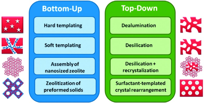
There are a number of ways to introduce a hierarchical pore structure, in which mesopores and micropores are connected, in zeolites. A review on hierarchical zeolites is presented by Li et al.,83 while other recent reviews on hierarchical zeolites are those by Na et al., Moliner, and Serrano et al. 84–86 Li et al. 83 describe, as summarized in Fig. 18, two approaches: bottom up, in which the hierarchical zeolite is synthesized directly from a silica-alumina gel, and top-down, in which existing zeolites are post-treated. In the bottom up-approach, extra-crystalline, hard, templates such as carbon black, 3-D ordered mesoporous carbon, or carbon aerogel can be used (e.g., ref. 87 and 88).
Fig. 18. Bottom-up and top-down approaches to hierarchical mesoporous zeolites. (Reproduced with permission from ref. 83, Copyright Wiley-VCH, 2014.).
The zeolites form within the structure of the hard template, which is then burnt off to create mesoporosity. Adaptations of the more standard templates, which introduce mesopore-structure direction in the same molecule, are called soft-templating. Here, different functionalities are combined in one template molecule that direct for micropores and mesopores. For instance, Ryoo et al. 89 describe hierarchical zeolites from randomly stacked MFI nanolayers, which are created by using special bifunctional organic structure directing agents. Rimer et al. 90 influence the crystallization kinetics by applying zeolite growth modifiers (ZGM), organic molecules that impede the growth of specific zeolite crystal planes. The conversion of amorphous cell walls of MCM-41 or SBA-15 type mesoporous materials towards crystalline zeolite structures (such as TUD-C,91 or zeolite Y encapsulated in TUD-192) is also considered bottom-up.
In the top-down approach to achieve hierarchical zeolites, the zeolites are post-treated after synthesis. The easiest way to introduce mesoporosity is by dealumination, which can be achieved by steaming and chemical treatments, such as acid leaching or reaction with EDTA or other chelating agents that remove the resulting extra-framework alumina. This approach was used in the development of Dow's 3DDM mesoporous mordenite catalyst for the production of cumene,93 and is also the basis of US-Y zeolites that are used in many applications nowadays.
Clearly, dealumination leads to a lower number of acid sites and at least an initial loss of framework integrity. However, these disadvantages are more than offset by the creation of new types of acidic sites and enhanced diffusion properties.94 The increased mesoporosity may give rise to increasing rates in bimolecular and oligomeric reaction pathways that require large transition states.95 Separating this effect from the modified acidity per site in explaining activity and selectivity differences can be a challenge. Janssen et al. provide a good insight in the formation of the mesopores in zeolite Y by applying 3D transmission electron microscopy (TEM) in combination with nitrogen physisorption and mercury porosimetry measurements.96 They find a large part of the mesopores in cavities within the crystal, and the creation of an interconnecting system of cylindrical mesopores requires special treatments.
Another way of producing mesopores is by desilication. Initial work in this field was published by Groen et al. 97,98 and expanded upon by Pérez-Ramírez et al. 99,100 The authors stress the need for a sustainable route, and note that most bottom-up approaches make use of exotic ingredients or larger amounts of organic templates than the original materials. Top-down approaches typically have low yields because they leach away either alumina or silica, and thus give rise to waste-streams. The authors note that a typical base leaching may remove as much as 30% of the parent material.101 They propose to use the silica-rich waste stream as a raw material in the original synthesis of the zeolite, thereby closing the material loop.99
Li et al. 102 compare mesoporous mordenites made with different synthesis methods. They applied soft and hard templating, as well as a combination of acid leaching and base treatment. Only the combination of acid leaching and base leaching yielded a material with improved accessibility and strong acidity, leading to optimal performance in the isomerization of 2-methyl-2-pentene and the alkylation of benzene with benzyl alcohol.
Park et al. 103 describe ZSM-5 based catalysts with hierarchical pore systems prepared with soft templating. When compared to normal ZSM-5 catalysts in the cracking of gas oil, they observe higher overall activity, and higher yield of lower olefins like propylene and butylene. The catalysts contain intracrystalline mesopores. The author assume that pre-cracking of larger molecules inside the mesopores provides the molecules that can be cracked inside the MFI micropores to give the desired products. Normal ZSM-5 would require conversion of gasoline range molecules to form the desired olefins, whereas the mesoporous catalysts described by the authors have similar or better gasoline yields compared to normal ZSM-5. However, the catalytic performance was tested on pure zeolite samples. The addition of matrix and binder, as well as the presence of a main Y-zeolite based FCC catalyst in the catalyst system, may cause the observed benefits to change, among others because this would supply a large concentration of gasoline molecules. The conversion and selectivity to propylene observed for the hierarchical ZSM-5 samples described by the authors is not high enough to warrant use by itself (see e.g. the performance characteristics of the DCC process104).
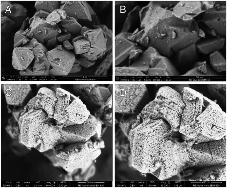
Hansen et al. 82 describe the introduction of uniform mesopores in the size range of about 4 nm, or about 6 times larger than the micropores in the host lattice of the zeolite (see Fig. 19), by a post-synthesis chemical treatment.83,105 We will expand a bit on this work, as it directly concerns an application in FCC. The authors observe a lower bottoms yield at constant coke, and improved middle distillate over bottoms selectivity in ACE testing. A similar effect is seen for the gasoline over LPG selectivity, since the optimum in the series pathway network is shifted to higher molecular weight. The post-synthesis treatment in this technology appears to amount to a re-crystallization of the zeolite in alkali (pH 9–11) in the presence of cetyl-trimethyl-ammonium-bromide (CTAB) at 150 °C. The starting zeolite in the original process already has a quite high silica-to-alumina ratio of about 30, lower SAR zeolites apparently need an acid pretreatment before they are suitable for post-treatment.106 Carbon residue from the template is removed by careful calcination at 550 °C. Following the treatment, the authors do not observe any octahedrally coordinated Al in the NMR spectrum, and terminal silanol vibrations at 3740 cm–1 also disappear, both indicating a lattice without too many irregularities. The vibration of the Brønsted acid site at 3640 cm–1 seems to increase compared to the parent material, as does a vibration at ∼3540 cm–1, on which the authors do not comment. TPD of ammonia shows that the mesostructured material has about the same number of acid sites as normal zeolite US-Y. The zeolites were tested after being introduced in FCC-matrices, and steam-deactivated. At constant conversion, lower bottoms- and coke-make, and higher gasoline and middle distillate yields are observed.
Fig. 19. FE-SEM images from untreated (top) and mesostructured (bottom) zeolite Y crystals. Scale bars: (a) 1 μm; (b and c) 500 nm; (d) 200 nm. (Reproduced with permission from ref. 83, Copyright Wiley-VCH, 2014).
García-Martínez et al. 107 describe a test with a commercial quantity of the material in a refinery. They tested the E-cat from the refinery in a FCC test unit before and at the end of the trial, and report lower coke make, higher LCO make and lower bottoms for the catalyst containing hierarchical zeolites.
4.4. New zeolites in fluid catalytic cracking
Although it is clear that improved mesoporosity in FCC catalysts improves the performance, this does not imply that ultra-large-pore zeolites are necessarily good active ingredients in FCC catalysts.108 In the cracking of model reactants like n-hexane, for instance, MCM-41 performs much poorer than zeolite US-Y. In the cracking of larger molecules, like gas oil cracking, the difference is smaller, but the low thermal stability of MCM-41 prevents its application under the severe FCC process conditions.
Early work by Derouane and co-workers109 explains this effect. The authors describe the role of the curvature of the zeolite pore surface and explain that the interaction between molecules and the zeolite surface is strongest when the radius of the molecule and the surface curvature are similar. At this exact fit, a number of phenomena are described that have a direct effect on the performance, e.g. a supermobility instead of Knudsen diffusion. The increased interaction leads to increased concentration of reactants near the acid sites, and expresses itself macroscopically as increased apparent acid strength. This implies that the 3D structure of the zeolite and its effect on sorption equilibria can play a large role in reaction kinetics; they directly influence the observed rate of reaction, especially when the sorption energetics are magnified by the surface curvature.110 This implies that the decreased rate of cracking of n-hexane in MCM-41 as compared to zeolite US-Y does not necessarily mean that the acid sites in MCM-41 are weaker than those in zeolite US-Y.
Apart from zeolite Y and ZSM-5, other zeolites have been tested in FCC catalysis. Zeolite Beta, for instance, has been studied extensively. Although economics and thermal stability have thus far prevented the application of zeolite Beta in large-scale FCC processes, it is known111–113 that (P-stabilized111) zeolite Beta improves C4-yields. Bonetto et al. describe an optimal crystallite size for stability, activity and selectivity for zeolite Beta in gas oil cracking.112 Mavrovouniotis et al. ascribe the higher olefinicity in the gases for zeolite Beta to a lower hydrogen transfer activity.113
The issue of cost and stability returns for many of the new structures proposed for FCC applications. Quite often, complicated organic SDAs, or exotic framework constituents (e.g. Ge and Ga), or fluoride-assisted syntheses are required to even synthesize (new) zeolite structures. These do not translate well to the scale of operation, catalyst consumption and the severity of the FCC process. Nevertheless, we will discuss some recent developments in the paragraphs below.
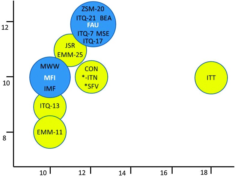
Fig. 20 gives an overview of some of the new zeolites tested in FCC as a function of their pore diameters. When examining the medium pore size zeolite MCM-22,114 Corma et al. observed little activity in the cracking of larger molecules. When using it in an additive similar to zeolite ZSM-5 additives, zeolite MCM-22 produces less gases (lower loss in gasoline yield), but with higher olefinicity (so higher propylene and butylene selectivity than ZSM-5). ZSM-5 is more active, though. ITQ-13115 with a 3D 9-MR × 10-MR pore system, presents acid sites that are similar in strength to those of ZSM-5, or stronger. The specific pore structure induces an increased yield of propylene in VGO cracking.
Fig. 20. New zeolites tried in FCC applications, ranked according to the size of their pore systems. Many of the new zeolites have mixed pore systems, allowing them to show performance in between the conventional zeolites ZSM-5 and Y.
Zeolite ITQ-7116 has a pore system similar to zeolite Beta, yet a higher gasoline yield and improved olefin selectivity are observed in FCC cracking, where an ITQ-7 containing additive was used.117 The authors conclude that the specific structure and tortuosity of the pore system favors β-scission over protolytic cracking and limits hydrogen transfer reactions.
Zeolite ZSM-20118 and ITQ-21119 both have structures that resemble zeolite Y, and pore openings that are similar in size to zeolite Y. Their cracking characteristics are similar to zeolite Y, except for a higher gas (LPG) and propylene yield but lower gasoline olefinicity in ITQ-21. Zeolite ZSM-20 shows good thermal stability compared to zeolite Y, but this does not directly translate into higher activity.
In their description of the new zeolite IM-5, Corma et al. 120,121 apply various cracking and isomerization tests (i.e., n-decane hydroisomerization–cracking, m-xylene isomerization–disproportionation, and n-hexadecane isodewaxing) and adsorption tests to study the pore morphology and suitability of the structure for cracking reactions. The structure is described as having 10-MR pores with side pockets, and performance of the material in some cases is close to ZSM-5, possibly with improved thermal stability.
Moliner et al. 122 describe the synthesis of ITQ-39, a new zeolite with a three-directional channel system with interconnected large (12-MR) and medium pores (10-MR). The zeolite performs well in the alkylation of benzene to cumene. The authors claim the material would be a good additive for FCC since its pore system behaves as an intermediate between zeolites ZSM-5 and Beta. The silica-germanate ITQ-33, from the same group123 is another zeolite with a mixed pore system, in this case an intersecting 18-MR–10-MR system. This material was compared to ITQ-17, a material with the same composition but only 12-MR pores, as well as zeolite Beta (3D 12-MR pores). Cracking experiments were performed with 1,3-diisopropylbenzene (DIPB) and 1,3,5-triisopropylbenzene (TIPB), i.e. relatively large molecules that do not easily fit in small pores (DIPB can diffuse through 12-MR pores, TIPB cannot). The authors conclude the material behaves like a 12-MR, i.e. it has a medium-strong acid site strength. The material was also tested in VGO cracking, yielding more middle distillates than zeolite US-Y or Beta at the same conversion.124 A catalyst mixture of ITQ-33 and ZSM-5 yielded more middle distillate as well as significantly more propylene than zeolite US-Y, even when the US-Y was also tested with ZSM-5 additive. Economics and stability of the material may impede its widespread application, though.
There are other new or fairly recently described materials that could be of use for FCC, but these have not been extensively discussed, such as the 11-MR systems JU-64 (JSR125) and EMM-25,126 and the 12-MR system MCM-68 (MSE127). Other structures with mixed pore systems include EMM-11 (10-8MR),128 and the 10-MR/12-MR systems SSZ-57 (*SFV129) and CIT-1/SSZ-26/SSZ-33/EMM-22 (CON130–132).
5. Changes in feedstock and new applications of FCC catalysts
5.1. Co-processing biomass-derived oxygenates with FCC catalysts
Due to growing awareness of depleting crude oil resources, rising CO2 levels, global warming and securing energy supply it would be advantageous to use biomass-derived feedstock in existing petroleum refineries.133 As petroleum refineries are already in place the use of this infrastructure for the production of fuels and base chemicals, such as propylene, from biomass requires – in principle – relatively little investment costs. An attractive, and already explored option is the co-processing of biomass-derived oxygenates with petroleum-derived fractions, such as VGO.
FCC of biomass-derived oxygenates gives products with higher hydrogen content than the starting biomass-based feedstock by removing oxygen as carbon monoxide as well as carbon dioxide, next to an increased amount of water. In addition, higher amounts of carbon deposits are found on the FCC catalyst material, which then can be burned off in the regeneration to produce process heat. Alternatively, the coke deposits formed by co-processing biomass with VGO during FCC can be converted into synthesis gas (CO + H2), which can be used elsewhere in the oil refinery. Another important issue relates to the significant content of water in biomass-derived oxygenates, which may not dissolve into VGO, although some options have been discussed by Corma and co-workers.134
In this article we focus on the catalytic cracking of biomass-derived feedstocks mixed with petroleum-derived feedstocks making use of real-life FCC catalyst materials. This topic has been the subject of several review articles and we refer here the reader to the excellent articles of Huber & Corma and Stocker for the required background and the various possibilities for catalytic cracking of lignocellulosic- and triglycerides-based feedstocks.135,136 Examples include sugars (glucose and xylose), sugar alcohols (e.g. xylitol and glycerol), lignin as well as vegetable oils. Other more recent review papers are of the hands of Al-Sabawi and co-workers137 and Kubicka and Kikhtyanin.138
Active research groups include those of e.g. Schuurman & Mirodatos [e.g. ref. 139–142], Kersten & van Swaaij [e.g. ref. 143–145], Naik & Kumar [e.g. ref. 146 and 147], Corma [e.g. ref. 134 and 148] and Lappas & Vasalos [e.g. ref. 149 and 150].
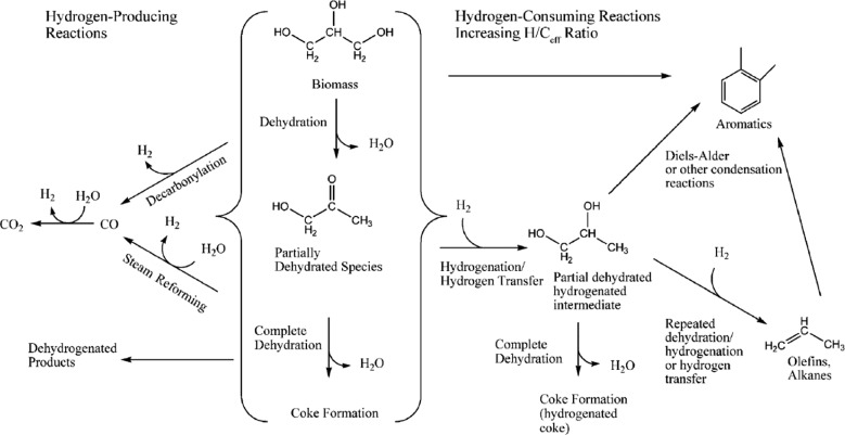
Fig. 21 summarizes the different reaction pathways for the catalytic cracking of biomass-derived oxygenates, which involves, according to Corma et al.,134 five different classes of reactions: (a) dehydration reactions, producing water; (b) cracking of large oxygenated biomass-based molecules into smaller molecules; (c) hydrogen-producing reactions; (d) hydrogen-consuming reactions; and (e) production of larger molecules by carbon–carbon bond formation. Although the FCC process in principle does not require hydrogen it can be produced through steam reforming and water–gas shift reactions as well as dehydrogenation and decarbonylation of biomass-derived molecules.
Fig. 21. Reaction pathways for the catalytic cracking of biomass-derived oxygenates. Reproduced with permission from ref. 135, Copyright Wiley-VCH, 2007.
A seminal mechanistic contribution in this field of research originates from the group of Schuurman and Mirodatos, who have explored the 14C technique – known to discriminate fossil carbon from bio-carbon since fossil fuel is virtually free of 14C, while biofuel contains the present-day amount of 14C – to determine how the carbon from the co-processed biomass re-distributes in the range of FCC products formed. This has been done by co-processing hydro-deoxygenated (HDO) bio-oil with VGO feedstock over an E-cat FCC catalyst. It was found that the bio-carbon was mainly concentrated in the gas fraction (10.6%) and in the coke deposits (15.8%), while the gasoline produced contains only around 7% of the bio-carbon. In other words, it was found that co-processing leads to a bio-carbon impoverished gasoline, and a bio-carbon enriched LPG product slate. Such an uneven bio-carbon distribution can be explained by the changes in the cracking routes during co-processing, arising essentially from the competitive adsorption of the polar oxygenated molecules and non-polar hydrocarbon molecules in the mesopore space of the FCC catalyst material. The HDO bio-oil molecules are preferentially cracked and deoxygenated into light gases, which seems to inhibit the production of bottom, LCO and gasoline from the VGO feedstock. The larger coke formation, which was noted to be richer in bio-carbon, could originate from the re-polymerization of phenolic compounds. Another part of the increased coke formation may originate from the depletion in hydrogen due to water formation.
A detailed study on the catalytic cracking of various bio-oil model compounds, which could be co-processed in an FCC unit, has been performed by Sedran and co-workers.151,152 This group has studied, making use of an E-cat FCC catalyst, the influence of various functional groups in biomass-derived molecules on the catalytic conversion, selectivity and coke levels, and compared them to those obtained for thermal cracking of the very same model compounds. More in particular, they have investigated the following biomass-derived model compounds: methanol (MEL), acetic acid (ACET), methyl acetate (MACET), furfural (FUR), 3-methyl-2-pentanone (MP), 2-hidroxy-3-methylcyclopenenone (HMCP), phenol (PHE), 2,6-dimethoxyphenol (SYR) and 1,2,4-trimethoxybenzene (TMBENZ). Table 1 summarizes the results of the thermal and catalytic cracking, including the conversion, as well as the yields of hydrocarbons, oxygenates, H2, CO2, CO, H2O and coke deposits.
Table 1. Thermal and catalytic conversion of various biomass-derived model compounds when using an E-cat FCC catalyst and a reaction temperature of 500 °C in a fixed bed laboratory reactor for 60 s. The selectivity is expressed as a distribution in wt% of the hydrocarbon products analysed. SiC was used as inert material in the reactor to simulate thermal cracking, while nr in the table implies not reported values.
| Model compound | Thermal or catalytic cracking | Conversion (%) | Yields (wt%) |
|||||||
| Hydrocarbons | Oxygenates | H2 | CO2 | CO | H2O | Coke | Unknown | |||
| Methanol | SiC | 22.6 | 0.2 | 5.4 | 2.4 | 0.8 | nr | 13.6 | 0.2 | nr |
| E-cat | 60.8 | 7.1 | 4.0 | 3.5 | 12.2 | nr | 27.0 | 5.5 | 1.7 | |
| Acetic acid | SiC | 45.0 | 10.4 | 5.0 | 17.5 | 8.2 | nr | 3.6 | 0.3 | nr |
| E-cat | 50.4 | 4.2 | 5.2 | 6.6 | 22.9 | nr | 9.9 | 1.6 | nr | |
| Methyl acetate | SiC | 95.3 | 0.4 | 81.6 | 5.2 | 3.0 | nr | 4.7 | 0.4 | nr |
| E-cat | 95.1 | 0.9 | 54.5 | 3.7 | 22.2 | nr | 6.4 | 7.4 | nr | |
| Furfural | SiC | 21.6 | 5.3 | 0.7 | 6.7 | 1.1 | nr | 6.8 | 1.0 | nr |
| E-cat | 78.2 | 32.1 | 9.0 | 5.7 | 9.6 | 1.8 | 12.8 | 7.2 | nr | |
| 3-Methyl-2-penta-none | SiC | 24.9 | 0.3 | 17.9 | 0.6 | 1.2 | nr | 3.1 | 0.1 | 1.7 |
| E-cat | 79.6 | 37.6 | 20.7 | 0.5 | 1.1 | nr | 13.7 | 5.9 | nr | |
| 2-Hidroxy-3-methyl-cyclopentenone | SiC | 37.7 | 5.0 | 14.4 | 3.7 | 1.9 | nr | 10.0 | 0.7 | 2.0 |
| E-cat | 84.5 | 14.0 | 9.4 | 8.1 | 35.7 | 1.2 | 2.3 | 12.8 | 1.0 | |
| Phenol | SiC | 8.2 | 0.2 | nr | 1.1 | 4.0 | nr | 2.8 | 0.1 | nr |
| E-cat | 54.9 | 34.9 | 2.0 | 1.6 | 4.0 | nr | 8.0 | 4.4 | nr | |
| Syringol | SiC | 56.7 | 0.4 | 39.0 | 3.0 | 7.5 | nr | 6.0 | 0.8 | nr |
| E-cat | 75.0 | 2.1 | 32.5 | 4.1 | 22.9 | nr | 4.9 | 8.5 | nr | |
| Trimethoxy-benzene | SiC | 97.1 | 57.8 | 3.4 | 2.3 | 32.9 | 0.3 | nr | 0.4 | nr |
| E-cat | 95.7 | 47.1 | 0.2 | 2.3 | 29.8 | 0.3 | nr | 16.0 | nr | |
It can be concluded from Table 1 that the catalytic cracking activity decreases in the order: TMB > MACET > HMPC > FUR > SYR > MET > PHE > ACET. These conversion levels are, with some exceptions (e.g. TMB), always higher for the catalytic cracking as compared to thermal cracking. Deoxygenation reactions, taking place via dehydration and decarboxylation, results in the production of CO2/CO and H2O, and was very important in all cases, but was very dominant for ACET, MACET, HMPC, SYR and TMB. Deoxygenation reactions were always much lower in the thermal conversions than in the catalytic conversions. The reverse was (almost) the case for coke deposit formation. The reaction products were also very different, ranging from mainly aromatics in the gasoline range for methanol and TMB, to C4-hydrocarbons of olefinic nature for PHE and SYR.
In a follow-up study, Bertero and Sedran have converted a raw and thermally processed pine sawdust bio-oil over an E-cat FCC catalyst and compared their findings with a synthetic bio-oil composed of MEL, ACET, MACET, FUR, HMCP, PHE, SYR and TMBENZ.153 It was found that with this biomass-derived feedstock mainly C4 olefins, oxygenates and coke were formed. In contrast, the synthetic bio-oil produced lesser hydrocarbons and more oxygenates and coke than the sawdust-derived feedstock. Thermal treatment of the raw bio-oil lead to an increased amount of hydrocarbons, and a decreased amount of coke deposits. As a side conclusion it was stated that the behavior of bio-oils over FCC-based catalysts could not be well-described by using mixtures of model compounds, indicating the need for real-life testing, including the use of a commercial FCC catalyst.
Within this context, it is important to refer to the very recent work of Petrobras, who have co-processed raw bio-oil and gasoil in an FCC unit making use of an E-cat FCC catalyst. De Rezende Pinho and co-workers have made use of a bio-oil, produced from the fast pyrolysis of pine woodchips, together with standard VGO in a 150 kg h–1 FCC demonstration-scale unit.154 When 10% bio-oil was co-processed, LPG, gasoline and LCO with similar product yields was obtained in comparison with the base VGO feedstock. Increasing this co-processing to levels of 20% bio-oil lead to some product quality deterioration. Very interesting experiments, complementing those of Fogassy and co-workers,142 were conducted with 14C isotopic labeled feedstock to determine the bio-carbon content in the FCC products. As mentioned above, the 14C isotopic analysis performed allowed distinguishing biomass-derived carbon from fossil carbon in the catalytic cracking products; naphtha (gasoline), LCO (diesel range) yield and bottoms. It was found that for 10% bio-oil in the feed, 2% bio-carbon was found in the total liquid product, while for 20% bio-oil in the feed, between 3 and 5% was found, while the bio-carbon in the LCO and bottoms was respectively 5 and 6%. Furthermore, a high amount of phenolic compounds was detected in the naphtha produced by the FCC process, while most of the oxygen present in the bio-oil was removed as water. Another interesting observation was the fact that less coke deposits were formed at this demonstration-scale production plant as anticipated based on literature data making use of lab-scale testing units. These differences should be attributed to the differences in scales as larger scales tend to improve the product qualities due to a better contact between catalyst and feedstock. These results show that co-processing of bio-oils in FCC is technically feasibly at the level of a demonstration plant making use of a practical E-cat FCC catalyst.
The KiOR company has recently explored the commercialization of their catalytic pyrolysis technology making use of FCC catalysts intimately mixed with finely grinded lignocellulosic biomass at a production facility in Columbus (MS, USA).155–157 KiOR uses equipment from the paper industry to dry and grind the biomass, which is fed into a modified FCC reactor loaded with a zeolite-based catalyst, performing the actual pyrolysis process. KiOR then separates the pyrolysis oil from the other reaction products and removes O2 by hydrogenation, using purchased H2. The resulting product is then distilled into fuels through standard oil refining technology. Unfortunately, the industrial activities of KiOR, which started around 2012, had to be stopped due to financial problems at the end of 2014.158
Within this context it is important to mention other commercial approaches of producing biomass-based fuels in a refinery, such as the one developed by Neste/Albemarle. The Neste process (NexBTL) deoxygenates fatty acids to yield alkanes and propane (i.e. no fatty acid esters or glycerol are produced) in a catalytic hydrogenolysis process using a proprietary set of catalysts. The process is used in plants in Porvoo, Singapore and Rotterdam, at nearly 2 million tpa capacity.159,160 Kalnes et al. describe a process which combines a deoxygenation stage with an isomerization stage to achieve the same conversion of fatty acids to diesel range alkanes.161
5.2. Processing tight oil and shale oil
One of the challenges facing especially USA-based FCC Units is the increasing use of tight oils. The oils are generally relatively light, and contain low amounts of sulfur and nitrogen and nickel and vanadium. Although all these parameters are generally good for FCC operation, there are also a number of drawbacks to using tight oils. Tight oil cracking gives high naphtha and LPG yields, but these are generally paraffinic, which makes it more difficult to reach octane number targets for the gasoline pool. This needs to be corrected by units outside the FCC complex, such as isoparaffin–olefin alkylation and reforming.162 Because the feedstock contains low Conradsen carbon residue, and low aromatics, it is also more difficult to control the coke deposition and thus the unit heat balance. One could say in some aspects that the feed is too easy to crack. The high naphtha and LPG yields can disturb the distillation units and gas plants after the FCC unit, thus limiting the FCC throughput. Although the feed is low on the normal impurities (S, N, Ni and V), tight oils generally contain increased levels of Na, Ca, and Fe.163 Especially the iron can lead to problems,164 since iron deposits on the outside of the FCC particles, forming lumps on the outer surface which can block the pores (as demonstrated by Meirer et al., see extended discussion below165). Na will of course potentially block the acid sites in the zeolite. The challenges described above can partly be addressed through process changes, and by the addition of additional VGO or resid feedstock to the unit. It is also evident that catalyst flexibility and tolerance to the specific contaminants need to be built into the FCC catalysts.162,163
5.3. FCC catalysts in other refinery applications
Thermal coking is a process used in refineries to convert the heaviest part of the crude, the “bottom of the barrel” into useful products. Three major processes exist in present day refineries: delayed coking, fluid coking, and flexicoking. Because the feedstocks used by refineries are getting heavier, the coker units are utilized more heavily, and may become limiting in refinery operations. Therefore, improvements have been developed to the processes. One of these is to introduce a catalyst-containing additive to the coker feed, and thus transform the thermal coking into (at least partially) a catalytic process. The catalysts applied in this technology are derived from FCC catalysts, since these show a high activity and selectivity to hydrocarbon under similar operating conditions (low pressure, low hydrogen partial pressure), the size requirements are similar, and they can easily and cost-effectively be tailored to meet a variety of demands. Catalysts proposed for this application thus comprise a combination of building blocks found in FCC catalysts (i.e., zeolite, matrix, clay and binder), but not necessarily all of them. This allows control of the cracking/coking ratio and the quality of both hydrocarbon products as well as the coke.166,167
6. Developments in FCC catalyst characterization
During the last two decades we have seen the merge between spectroscopy and microscopy leading to the conception of different micro-spectroscopy approaches.168 These promising characterization techniques now find their way in the field of heterogeneous catalysts, including the characterization of FCC catalysts at the single particle level. It is interesting to observe that at various synchrotron radiation facilities single catalyst particle characterization tools are now becoming available making it possible to compare bulk characterization data with single catalyst particle analysis. A similar trend can be found at analytical companies, which have introduced in recent years a variety of Raman, UV-Vis, IR and fluorescence microscopes, often in combination with microscopy accessories, including scanning/transmission electron microscopy (SEM/TEM) and atomic force microscopy (AFM).
In the following paragraphs, we describe the possibilities and limitations of these micro-spectroscopy techniques, as applied to FCC catalyst materials, for shedding new insight in the 2D and/or 3D distribution of (a) metal poisons, (b) acid sites, (c) pore network accessibility and connectivity and (d) ultra-structures, including the zeolite and different matrix components (i.e., clay, silica and alumina).
6.1. X-ray-based characterization methods
Ruiz-Martinez et al. 169 have used a combined characterization set-up, comprising μ-X-ray fluorescence (XRF), μ-X-ray absorption near edge spectroscopy (XANES) and μ-X-ray diffraction (XRD), developed at the I18 beamline of the Diamond Light Source. This set-up allows to investigate for the same FCC catalyst particle the 2-D distribution of metal poisons, such as Ni and V, their oxidation state, as well as the presence of the different ultra-structures embedded in the FCC catalyst particle.
The 2D spatial resolution is 5 μm. This approach is illustrated in Fig. 22 for a fresh FCC and an E-cat catalyst particle. As one can expect, the fresh FCC catalyst particle did not contain any appreciable amount of Ni and V, to be detected by the μ-XRF method. Interestingly, high quality XRD patterns could be obtained by the μ-XRD approach, which allowed distinguishing between the diffraction patterns of zeolite Y, clay and boehmite. Moreover, the relative intensity of the diffraction peaks, as well as their exact position, can be used to determine the relative contribution of zeolite Y, as well as the Si/Al ratio of the embedded zeolite aggregates.
Fig. 22. Combined μ-XRF/μ-XANES/μ-XRD data of a single FCC catalyst particle in its fresh state (top) and deactivated state (bottom). Left: μ-XRF 2D chemical maps of Ni (a and g) and V (b and h). Right: μ-XRD 2D chemical maps of zeolite Y (c and i), clay/mullite (d and j), boehmite/γ-alumina (e and k). Far right: 2D reconstructions of the Si/Al ratio for the fresh (f) and deactivated (l) FCC catalyst particle. (Reproduced with permission from ref. 169, Copyright Wiley-VCH, 2013.).
From Fig. 22c one can conclude that zeolite Y is a randomly distributed, although the embedded zeolite material is not entirely homogeneously present in the catalyst matrix, and some hot spots of high amounts of zeolite Y are found. Furthermore, when considering the Si/Al ratio it can be noticed that this value is rather homogeneous across the entire catalyst particle. In strong contrast, the results for the E-cat catalyst particle are entirely different from those of the fresh FCC particle. First of all, it is obvious from Fig. 22g and h that both Ni and V are present as metal poisons, and that Ni (in green) is present in an egg-shell distribution, whereas V (in blue) penetrates deeper into the inner parts of the FCC catalyst particle. μ-XANES confirmed that V and Ni were mainly present in respectively their 5+ and 2+ oxidation state. Finally, μ-XRD revealed that the diffraction patterns of zeolite Y were much less intense as in the case of the fresh FCC catalyst particle. Furthermore, a distorted egg-shell distribution could be observed for both the relative intensities of zeolite Y (Fig. 22i) and the Si/Al ratio (Fig. 22l). Furthermore, the Si/Al ratio values are much higher than those observed for the fresh FCC catalyst particle (Fig. 22f), indicating that severe dealumination has taken place during metal poisoning, and subsequent catalyst regeneration.
Meirer and co-workers170 have been using element-specific X-ray nano-tomography to investigate the 3D structure of a whole individual FCC catalyst particle at high spatial resolution and in a non-invasive manner. This was done by using a full-field X-ray absorption mosaic nano-tomography set-up at beamline 6.2 of the Stanford Synchrotron Radiation Lightsource, providing better than 30 nm 2D spatial resolution. With this instrumentation it was possible to map the relative spatial distribution of the metal contaminants, Ni and Fe, and correlate these distributions to porosity and permeability changes of an E-cat catalyst particle. Both Ni and Fe were found to accumulate in the outer layers of the catalyst particle, although Ni was found to penetrate in the deeper layers than Fe, effectively decreasing the porosity by clogging the macropores and thereby restricting access into the catalyst particle. This is illustrated in Fig. 23, which shows the permeability calculation of a sub-volume of the E-cat particle of 16.6 × 16.6 × 10 μm3 in size, in which Fe is found in lower concentrations than at the outer catalyst surface, while Ni is more concentrated at the top of the selected sub-volume (Fig. 23b). By simulating the fluid flow through this sub-volume, two distinct effects could be revealed. First, the authors observed a constriction of flow where Ni is present, indicated by the high velocity (red area, Fig. 23c) fluid flow through small cross sectional areas. Elsewhere in the region, with little to no Ni, flow is less inhibited (blue streamlines, Fig. 23c). Secondly, there were areas with large Ni content, which were totally inaccessible because the Ni is clogging some macropores completely.
Fig. 23. X-ray nanotomography study of an E-cat catalyst particle, revealing the relative spatial distributions of Ni and Fe and their effect on the macropore structure and accessibility. A sub-volume of 16.6 × 16.6 × 10 μm3 was selected (b) out of the entire catalyst particle of 44.8 × 52.7 × 51.2 μm3 in size (a), including the relative Fe and Ni distributions. Permeability calculation was applied on this sub-volume (c). Mass transport through the sub-volume along the selected axis (red arrow) is visualized using the velocity field of the fluid. The streamlines indicate the magnitude of the velocity field where red represents the highest velocity (i.e., where the pore space constriction is the largest) and blue indicates the lowest velocity. (Reproduced with permission from ref. 170, Copyright American Chemical Society, 2015).
Another observation made possible by this X-ray nano-tomography study was that valleys and nodules at the outer surface of the FCC catalyst particle were observed, which are similar to those seen in surface topography studies of E-cat samples. Fe was found to be distributed along these valleys and nodules, showing the largest amounts in the top 1 μm outer layer of the E-cat catalyst particle.
The X-ray nano-tomography work of FCC catalyst particles was recently expanded in two papers correlating 3D Fe and Ni contamination with porosity and pore connectivity in individual FCC particles, showing how gradual pore clogging could explain the progressive deactivation of FCC catalysts due to metal poisoning.165 This was done by making use of a unique set of four FCC catalyst particles: i.e., a fresh FCC catalyst particle and three E-cat catalyst particles with increasing metal loading. The latter three particles were obtained by performing a density separation step on a well-characterized E-cat sample. In a subsequent step, X-ray nano-tomography was used to quantify in the changes in single-particle macroporosity and pore connectivity for these four FCC catalyst particles and correlate them with Fe and Ni deposition. Both Fe and Ni were found to be gradually incorporated almost exclusively in the near-surface regions of the FCC catalyst particles, severely limiting the macropore accessibility as metal concentrations increase. Because macropore channels can be regarded as “transportation highways” of the pore network, blocking them prevents crude oil feedstock molecules from reaching the catalytically active domains. Consequently, metal deposition reduces the catalytic conversion with increasing time on stream because the internal pore volume, although itself unobstructed, becomes largely inaccessible. Furthermore, it was found that metal accumulation at the near-surface regions plays a role in FCC catalyst particle agglutination.171 This was concluded based on a detailed analysis of the concentration distribution of Fe and Ni in a system of agglutinated FCC catalyst particles. It was found that the interfaces between the agglutinated catalyst particles have metal concentrations above the average near-surface concentrations, suggesting that the surface accumulation of Fe and Ni could lead to increased particle clustering, hence decreased cracking activity.
Bare and co-workers172 have been studying E-cat catalyst particles at both the ensemble and single particle level making use of a combination of X-ray micro- and nano-tomography as well as μ-XRF and μ-XRD. The X-ray micro- and nano-tomography were performed at respectively beamline 2-BM of the Advanced Photon Source and the X8C beamline of the National Synchrotron Light Source, whereas μ-XRF and μ-XRD data were acquired at beamline ID-D of the Advanced Photon Source. X-ray micro-tomography was used to determine the average size and shape, and their respective distributions, of over 1200 individual E-cat catalyst particles. As shown in Fig. 24a it was found that a large fraction of the E-cat particles contained large internal voids, which certainly affect the particles' density, including their accessibility, and catalytic activity. Fig. 24d shows the equivalent diameter of the internal voids within these E-cat catalyst particles, illustrating that most of them are in the range of 5–15 μm, whereas still several can even exceed the 25 μm size. 2-D transmission X-ray microscopy images of both situations are shown in respectively Fig. 24b and c.
Fig. 24. (a) Single slice of the X-ray micro-tomogram of E-cat particles inside a polyimide tube, which is the circle around the image. The E-cat catalyst particles have a range of shapes and sizes, and some are hollow. Some of them are indicated by the red circles in the image; (b and c) 2D transmission X-ray microscopy images of sections of two E-cat particles showing different sizes of internal voids, which are the dark colored regions in the images; and (d) equivalent diameter of internal voids in the set of E-cat catalyst particles as investigated with X-ray micro-tomography. (Reproduced with permission from ref. 172, Copyright Wiley-VCH, 2014).
X-ray nano-tomography revealed, in addition to these large micrometer-sized pores, voids in the sub-micrometer range, with macropores as small as 100 nm in diameter. Furthermore, the method was able to resolve different ultra-structures, such as clay, TiO2, and La-stabilized zeolite Y.
The μ-XRF measurements performed by the authors revealed that Ni was preferentially located on the exterior of the E-cat particles, while V was more deposited throughout the catalyst particle, confirming the observations of Ruiz-Martinez et al. 169 Finally, the measured μ-XRD patterns allowed the identification of the zeolite La–Y aggregates present, including the determination of the lattice parameters of zeolite Y, providing direct insight in the dealumination degree of the material.
Da Silva et al. 173 used a combination of phase-contrast X-ray micro-tomography and high-resolution ptychographic X-ray tomography to investigate a model FCC catalyst body, consisting of a mixture of 5% La2O3-exchanged zeolite Y and metakaolin, at the single particle level. The two types of tomographic methods have been performed at the TOMCAT and cSAXS beamlines of the Swiss Light Source. Fig. 25 illustrates the results as obtained with ptychographic X-ray tomography operating at a 3D spatial resolution of 39 nm. Fig. 25a shows a vertical slice of the electron-density tomogram for the FCC catalyst body. The two distinct material phases present can be clearly distinguished, and the upper and some lateral parts that appear brighter indicate some re-deposition of materials during the focused ion beam (FIB) milling of this model FCC catalyst particle.
Fig. 25. Ptychographic X-ray nano-tomography data on a model FCC catalyst body consisting of 5% La2O3-exchanged zeolite Y and metakaolin. (a) Vertical section from the middle of the electron-density tomogram. Both materials are indicated by the arrows and could be identified via their different electron density. (b) Some selected axial sections of the phase-contrast tomogram. The colored squares at the top-left corner correspond to the positions of the colored lines in (a). (c–f) 3D rending of metakaolin in blue, zeolite Y in red, and pores in light blue. (g and h) Two orthogonal sections from the middle of the tomogram, some enclosed pores are shown in blue. The scale bars are 1 μm. (Reproduced with permission from ref. 173, Copyright Wiley-VCH, 2015).
Fig. 25b presents a selection of axial sections for different vertical positions of the tomograms obtained, with the different colored squares reflecting different heights in the catalyst body shown in Fig. 25a. The top region is mostly metakaolin with only few spots of zeolite material, whereas the deeper parts contain more zeolite material. The zeolites are round and porous, whereas the metakaolin is more square-shaped, and these differences in morphology also lead to the formation of interparticle pores of irregular shapes. By taking into account the mass density differences between 5% La2O3-exchanged zeolite Y and metakaolin it has been possible to obtain the 3D rendering of both components, as shown in Fig. 25c–f. Here, the metakaolin clay, zeolite and pores are colored in blue, red and light blue, respectively. As the spatial resolution of the ptychographic X-ray tomography method is in the same range as that of mercury porosimetry, this methodology has been applied on the model FCC catalyst material under investigation. It was found that there was a fairly good agreement with the pore diameter range as probed with the local and global characterization method.
Kalirai et al. have recently used synchrotron-based multi-element XRF tomography with a large array Maia detector to investigate the 3-D distributions of metal poisons (i.e., Fe, Ni, V and Ca) and structural markers (i.e., La and Ti) within individual, intact and industrially deactivated FCC catalyst particles at two different catalytic life-stages.174 This study was performed making use of the recently developed set-up at the PO6 beamline at the Petra III synchrotron (DESY, Hamburg, Germany). It was found that for all metal poisons under study there is a radial concentration gradient where there is a maximum near the surface of the catalyst particle, gradually decreasing towards the particle's interior. Correlation analysis of the metal poisons revealed that Fe, Ni and Ca are highly correlated, particularly at the particle's exterior, where they form a shell around the FCC catalyst particle. V clearly penetrates further into the particle. This is illustrated in Fig. 26. However, no spatial correlation was found for V with La, hinting that V does not specifically interact with the zeolite domains and is present near the Al2O3-based matrix components of the catalyst particle.
Fig. 26. Comparison of clustering masks for the metal poisons Fe, Ni, V and Ca for an individual E-cat FCC catalyst particle for the correlation pairs Fe/Ni, Fe/V and Fe/Ca as determined with X-ray micro-fluorescence tomography. (Redrawn from ref. 174).
6.2. Visible and infrared light-based characterization methods
Buurmans, Ruiz-Martinez and coworkers175 have developed a set of selective staining reactions, which are catalyzed by Brønsted acid sites, making it possible to localize zeolite aggregate domains with a confocal fluorescence microscope. More specifically, various thiophene and styrene derivatives could be oligomerized selectively within the pores of zeolites Y and ZSM-5 embedded in an FCC catalyst matrix. As the resulting probe molecule oligomers have a distinct optical spectrum in the visible region of the spectrum, it was possible to excite the oligomers formed with an appropriate laser excitation in a confocal fluorescence microscope with a 2D spatial resolution of 500 nm. This selective staining approach is illustrated in Fig. 27 for two fresh FCC catalyst particles, one containing zeolite Y, whereas the other one was devoid in zeolite material. Clearly, green spots in the size of 2 μm or smaller could be discerned, which were clearly absent in the FCC catalyst particle containing no zeolite Y. Based on this selective staining approach three industrially relevant deactivation methods, namely steaming (ST), two-step cyclic deactivation (CD) and Mitchel impregnation-steam deactivation (MI), have been evaluated, and compared with both fresh FCC and E-cat samples.
Fig. 27. Confocal fluorescence microscopy images showing the visualization of zeolite Y aggregate domains within an FCC catalyst particle with (a and b) and without (c and d) zeolite material. The images were obtained after reaction with thiophene (green) at 373 K and subsequent staining with Nile Blue (red) at 298 K. Images b and d are magnified views of the highlighted areas in a and c, respectively. (Reproduced with permission from ref. 175, Copyright Macmillan Publishers, 2011).
A statistical analysis of the fluorescence microscopy data obtained for the two sets of FCC catalyst materials (labeled as FCC1 and FCC2), originating from two different manufacturing routes, are shown in Fig. 28. By comparing the fluorescence intensity values for the FCC1 and FCC2 catalyst batches, the reliability of the staining method has been verified. The fluorescence microscopy images for the fresh and deactivated FCC1 and FCC2 catalyst batches were very similar, as was there average fluorescence intensities. Interestingly, the fluorescence intensity trend follows the order: Fresh > ST > CD > MI. Because sufficiently strong Brønsted acid sites are needed for the formation of fluorescent carbocations upon e.g. thiophene oligomerization, this means that the amount of strong acid sites has decreased following the severity of the applied deactivation method. The sustained accessibility of the internal volume was confirmed with a staining reaction with the unreactive Nile Blue, which is too large to enter the zeolite pores. Furthermore, it was found that the E-cat sample has a fluorescence intensity, hence acidity, value in between that of the CD and MI FCC catalyst particles.
Fig. 28. Statistical analysis of the confocal fluorescence microscopy data obtained after thiophene selective staining for two different batches of FCC catalyst particles (FCC1 and FCC2, in orange and purple, respectively), which have been subjected to different degrees of deactivation; i.e., fresh, two-step cyclic deactivated (CD), Mitchell impregnated-steam deactivated (MI). For comparison, data for an E-cat sample have been added to the diagram in black. The fluorescence mean intensities and their corresponding standard errors have been determined from the statistical analysis of at least 150 zeolitic domains in the confocal fluorescence microscopy images of the different batches of FCC catalyst samples. (Reproduced with permission from ref. 175, Copyright Macmillan Publishers, 2011).
These findings have been corroborated by catalytic cracking activity measurements, as well as bulk XRD, IR spectroscopy after pyridine adsorption, TPD of ammonia and N2 physisorption measurements. These additional bulk characterization data on the two sets of FCC catalyst batches confirmed that the developed confocal fluorescence microscopy data are in line with the observed Brønsted acidity trends. Finally, the advantage of developed single particle analysis approach is that the average fluorescence intensity per individual FCC catalyst particle can be determined. This is shown in Fig. 29. It was found that the range of fluorescence intensities observed for the E-cat sample is wider than for CD and MI combined, reflecting the large interparticle heterogeneity in terms of age, Brønsted acidity and catalytic activity within an industrial E-cat sample. Interestingly, a similar wide range in fluorescence intensity, hence Brønsted acidity, was also observed for fresh FCC catalyst particles.
Fig. 29. Interparticle Brønsted acidity mapping for seven FCC1 catalyst particles, which have been subjected to different degrees of deactivation; i.e., fresh, two-step cyclic deactivated (CD), Mitchell impregnated-steam deactivated (MI), and their comparison with the mapping results of seven E-cat catalyst particles. (Reproduced with permission from ref. 175, Copyright Macmillan Publishers, 2011).
In a follow-up manuscript, Buurmans and co-workers176 have extended their selective staining approach of FCC catalyst particles for the determination of reactive zeolite ZSM-5 and Y aggregates within single FCC catalyst particles making use of 4-fluorostyrene and 4-methoxystyrene as probe molecules. Both styrene derivatives have different oligomerization reactivities, 4-fluorostyrene preferentially visualizing strong Brønsted acid sites, whereas 4-methoxystyrene as staining molecule reveals both weak and strong Brønsted acid sites.
It was found that the zeolite ZSM-5 aggregates are 1–5 μm in size and are inhomogeneously distributed within the FCC matrix. Fresh as well as three distinct laboratory-deactivated catalyst particles were studied upon reaction with the two styrene derivatives. When comparing these four sets of zeolite ZSM-5-containing FCC catalyst particles the Brønsted acidity decreases in the order: fresh > steamed > CD > MI. In the case of ZSM-5 as zeolite material, the same activity trends were obtained for 4-methoxy- and 4-fluorostyrene as probe molecule. However, this was not the case for the zeolite Y-containing FCC catalyst particles. It was found that these FCC catalyst particles show lower fluorostyrene intensity values upon reaction with 4-fluorostyrene, suggesting that not every acidic site within the catalyst particles has sufficient strength to convert 4-fluorostyrene into fluorescent carbocations. In other words, a large fraction of the Brønsted acid sites could be visualized with the less-demanding 4-methoxystyrene, while only a small fraction is observed upon reaction with 4-fluorostyrene. This observation is indicative for the higher Brønsted acid site diversity in FCC catalyst particles containing zeolite Y as compared to FCC catalyst particles containing zeolite ZSM-5. This conclusion is corroborated by ammonia TPD results on the same set of FCC catalyst materials. Indeed, the ammonia TPD curve for the FCC catalyst containing ZSM-5 shows a more well-defined pattern, which corresponds well with the more homogeneous Brønsted acid strength deduced from the confocal fluorescence microscopy experiments.
Sprung and Weckhuysen177 refined the confocal fluorescence microscopy approach for single FCC catalyst particles, containing ZSM-5, and determined the size, distribution, orientation and amount of zeolite ZSM-5 aggregates within binder material. More specifically, by making use of the anisotropic nature of zeolite ZSM-5 crystals and its interaction with plane-polarized laser light it turned out to be possible to distinguish between zeolite ZSM-5 aggregates and the various binder materials (i.e., alumina, silica and clay) after staining the FCC catalyst particles with 4-fluorostyrene as a probe molecule. It was found that the amount of detected fluorescent light corresponds to about 15 wt% of zeolite material, whereas statistical analysis of the emitted fluorostyrene light indicated that a large number of ZSM-5 domains appeared in small sizes of ∼0.015–0.25 μm2, representing single zeolite crystals or small aggregates thereof. On the other hand, the highest amount of the zeolite ZSM-5 material within the FCC matrix was aggregated into larger domains (ca. 1–5 μm2) with more or less similarly oriented zeolite crystallites.
Unfortunately, the confocal fluorescence microscopy approach described above cannot resolve sub-micrometer zeolite domains in great detail, and does also not provide any quantitative information about catalytic activity of the individual zeolite aggregates dispersed within the FCC matrix. For this purpose, single molecule fluorescence microscopy can be called in as a very sensitive and informative method. Ristanovic and co-workers178 have very recently reported the first application of single-molecule fluorescence microscopy and the required data analysis methods to quantitatively investigate Brønsted acidity and related catalytic activity in a single FCC catalyst particle containing ZSM-5. The approach developed in this work has a 2D spatial resolution of 30 nm; the approach and related results are summarized in Fig. 30.
Fig. 30. (a) Schematic of the single-molecule fluorescence approach developed for visualizing reactivity within a single FCC catalyst particle, containing zeolite ZSM-5 domains, which are depicted in red. (b) Formation of the fluorescent products (red) upon oligomerization of non-fluorescent furfuryl alcohol (black) on a Brønsted acid site. (c) The geometry of the analyzed focal slices and denoted focal depths. The inner regions of the FCC catalyst particles, depicted in gray, were not included in the data analysis. (d) A wide-field fluorescence micrograph of an FCC particle recorded during the oligomerization of furfuryl alcohol. The white circles indicate localized fluorescence bursts originating from the fluorescent products. (e) A photo-trajectory of a representative single catalytic turnover, indicated with a white arrow in (d). (f) A cluster analysis of the zeolite ZSM-5 domains size within a single FCC catalyst particle has been applied on different SOFI images, in this case one taken at a focal depth of 1 μm. (g) Histogram of the zeolite domains size distribution originating from the SOFI image in (f). (h) SOFI image of a selected 1 μm2 region of interest indicating the fluorescent zeolite domains. (i) Catalytic turnover rate as a function of average brightness in the SOFI image, calculated for 65 individual zeolite domains. (Reproduced with permission from ref. 178, Copyright Wiley-VCH, 2015).
To selectively study the zeolite ZSM-5 domains within the FCC catalyst particles the oligomerization of furfuryl alcohol was used as a selective probe reaction. The 532 nm laser light can excite the fluorescent oligomers formed from the non-fluorescent furfuryl alcohol monomers when brought in contact with Brønsted acid sites. The individual fluorescent reaction products are detected with a very sensitive detector and a typical fluorescence trajectory of an individual hotspot can be visualized (Fig. 30e). Fig. 30d shows a 2D wide-field fluorescence micrograph of an FCC particle, in which the white circles indicate localized fluorescence bursts originating from the fluorescent oligomerization products. In a next step, a statistical analysis procedure has been developed to obtain accumulated reactivity maps for Brønsted acid domains present within the FCC catalyst particles. An example of a so-called SOFI map is shown in Fig. 30f, which has been obtained for a focal depth of 1 μm. Interestingly, these SOFI maps allow to determine the aggregate sizes of the zeolite ZSM-5 domains and Fig. 30g shows a histogram of the zeolite domains distribution. It can be seen that most of the zeolite ZSM-5 domains are well-dispersed and range in their size between 0 and 0.2 μm2.
This is in good agreement with the zeolite ZSM-5 dispersion data described earlier by Sprung and Weckhuysen,177 although the single molecule fluorescence microscopy study now allows to obtain much higher spatial resolution, as illustrated in Fig. 30h. Another advantage of the single molecule spectroscopy approach is that it enables to put reactivity numbers on the visualized zeolite ZSM-5 aggregates. More specifically, the intensity map in Fig. 30h reveals the presence of zeolite aggregate domains, which have almost no reactivity towards furfuryl alcohol, whereas other zeolite aggregate domains are much more reactive. As a consequence, one can plot the SOFI brightness of distinct zeolite ZSM-5 domains as a function of their measured turnover rates. This approach is shown in Fig. 30i, which indicates that the most active zeolite ZSM-5 domains differ approximately an order of magnitude in reactivity when compared to the less active zeolite ZSM-5 domains. These reactivity differences should be related to differences in the framework aluminum content of the embedded zeolite domains and/or local accessibility differences.
Another powerful chemical imaging technique, namely IR microscopy with a 2D spatial resolution of 10 μm, has been explored by Buurmans et al. 179 and applied on single FCC catalyst particles containing zeolite Y, either in their fresh or deactivated state. By investigating a population of 15 FCC catalyst particles, after adsorption of pyridine, it has been possible to evaluate both Brønsted and Lewis acidity at the single particle level. Comparable acidity trends have been obtained as with bulk pyridine transmission IR spectroscopy and they follow the same reactivity order as described before when using confocal fluorescence microscopy; i.e., Fresh > ST > CD > MI. In other words, the IR microscopy data corroborate the data obtained with confocal fluorescence microscopy, indicating that it is now possible to reliably access Brønsted acidity within FCC catalyst particles at the single particle level. Moreover, the single FCC catalyst particle IR study revealed large interparticle heterogeneities in both Brønsted and Lewis acidity within the different FCC catalyst batches. Interestingly, and in line with the data described in Fig. 29, E-cat catalyst particles possess a significantly wider variety in Brønsted acidity as compared to CD and MI FCC catalyst particles, which may be explained by the age distribution in the E-cat.
6.3. Correlative characterization methods
Ideally one would like to link reactivity differences to information on the ultra-structures of the different components present within a single FCC catalyst particle. This has recently become possible by using an integrated laser and electron microscope (iLEM) as a chemical imaging method, as demonstrated by Karreman and co-workers,180 and by combining fluorescence microscopy with Focused Ion Beam-Scanning Electron Microscopy (FIB-SEM) imaging, as explored by Buurmans, De Winter, and co-workers.181,182 The iLEM technique combines the strength of a regular fluorescence microscope with that of a transmission electron microscope (TEM), but now performed in one set-up. It enables the rapid identification of fluorescent domains after applying a selective staining procedure and subsequent investigation of these regions with superior spatial resolution as provided by TEM.
To make this possible FCC catalyst particles containing zeolite Y has been first stained taking 4-fluorostyrene as probe molecule, followed by embedding the stained FCC catalyst particles within a resin. In a next step thin sections of the FCC material have been made and placed on a TEM grid. In a first step fluorescence microscopy images have been collected to determine the relative fluorescence of specific domains in the sliced FCC catalyst particles, followed by a detailed TEM analysis of the ultra-structures, which show (in different degrees) fluorescence upon staining, or simply are not fluorescent. The iLEM method, as applied to a fresh FCC catalyst particle, allowed the identification of areas mainly consisting of zeolite Y, present as structures with dimensions of a few hundred nanometers that display a very strong structural resemblance to pure zeolite Y, which became fluorescent after catalyst staining. Electron diffraction patterns confirmed the presence of zeolite Y. Other areas, which did not show any appreciable fluorescence upon catalyst staining, consisted of matrix material and for example plate-like components, assumed to be clay particles, as well as amorphous material could be observed. Finally, areas with intermediate fluorescence intensity upon catalyst staining revealed the presence of a mixture of zeolite, clay and amorphous material. To further explore the iLEM method an FCC catalyst material hydrothermally deactivated with steam has been investigated. In contrast to fresh FCC catalyst particles, steamed FCC catalyst particles showed much lower fluorescence intensity. Furthermore, the steam treatment also affected the zeolite Y structure as a large fraction of the crystals was damaged and appeared macroporous. Electron diffraction experiments indicated that in addition to the diffraction maxima of zeolite Y, also small γ-Al2O3 crystallites were present.
In a follow-up study, Karreman et al. 183 have systematically investigated a large set of iLEM images obtained for stained FCC catalyst particles, either fresh or steamed, as well as stained E-cat catalyst particles. This enabled the identification of a wide variety of ultra-structures, which are summarized in Fig. 31. In addition to the expected undamaged zeolite and clay domains, which are exclusively present in the fresh FCC catalyst particles, also mesoporous, macroporous, clotted and severed zeolite domains could be discerned. Furthermore, it was found that next to amorphous regions also fragments and damaged clay domains can be present. Fig. 32 illustrates the advantage of the iLEM method by focusing on the presence of clotted zeolites, which occur almost exclusively in E-cat catalyst particles. One can notice that in the outer surface region of the red-colored fluorescent E-cat catalyst particle there is a region which has a clear ultra-structure, but which is non-fluorescent.
Fig. 31. Representative TEM images of various structural features observed in fresh and steamed FCC catalyst particles, as well as E-cat catalyst particles. (Reproduced with permission from ref. 183, Copyright Wiley-VCH, 2013).
Fig. 32. (a) Fluorescence microscopy/TEM overlay image of a brightly fluorescing FCC particle slice. (b) Zoom-in of (a) in which the black rectangle shows the periphery of the particle, which is not fluorescent. (c) TEM imaging of the area boxed in (b) confirming the presence of a rim of clotted zeolites surrounding this FCC catalyst particle. (Reproduced with permission from ref. 183, Copyright Wiley-VCH, 2013).
This non-fluorescent layer is about 1 μm thick, and a further zoom-in revealed that it consists of 200–500 nm-sized crystallites. It was assumed that these clotted zeolite crystals, with very low or no Brønsted acidity, are poisoned with metals, such, as Fe, Ni or V, as one may expect from the higher described X-ray micro- and nano-tomography studies.
In an analogous manner, Buurmans, de Winter and co-workers have first stained the zeolite domains within individual FCC catalyst particles by making use of 4-fluorostyrene as probe molecule, followed by subsequently FIB-milling the catalyst particle, followed by imaging the porosity network with SEM.181,182 Fig. 33 shows a snapshot of the porous network of an FCC catalyst particle, including a fluorescence microscopy image, illustrating that both zeolite domains and porosity can be imaged, and both types of information can be correlated.
Fig. 33. (a) SE SEM image of an FCC catalyst particle. (b) BSE SEM image; (c) confocal fluorescence microscopy image (λ ex = 561 nm, detection 570–620 nm, false color image) and (d) overlay of the BSE SEM image with the confocal fluorescence microscopy image for the particle depicted in (a) after milling away a 7 μm thick slice using the FIB. (e) Three-dimensional reconstruction of the porous network in a volume of 24.6 × 12.1 × 2.0 μm of an FCC particle, constructed from the combination of a number of FIB-SEM images. Macropores are shown in blue, the external surface is shown in yellow. Reproduced from ref. 181.
From the detailed iLEM characterization study Karreman and co-workers have proposed a model for the functional and structural degradation of zeolite Y crystals in FCC and E-cat catalyst particles. This is summarized in Fig. 34. FCC catalyst particles have a different deactivation route than E-cat catalyst particles. In the case of an E-cat catalyst particle, deactivation occurs mostly through fragmentation and/or decrystallization of zeolite crystals and the formation of meso- and macropores (Fig. 34, right hand side). Furthermore, the observed “clotting” of mesoporous zeolites (Fig. 34, left hand side) is limited to E-cat materials. In contrast, steam deactivation strongly induces the severing of the zeolite Y crystals, while the formation of fragments in these samples is very rarely observed. The latter indicates that the formation of fragments is a phenomenon reserved for the harsh industrial catalytic cracking conditions.
Fig. 34. Model for the functional and structural degradation of zeolite Y crystals in FCC catalyst particles in an industrial catalytic cracking unit. The right placed red arrow indicates the relative change in fluorescence intensity measured for each ultra-structure feature. (Reproduced with permission from ref. 183, Copyright Wiley-VCH, 2013).
Although the zeolite degradation model, described in Fig. 34, suggests a continuous process of FCC catalyst particle degradation, various degradation stages were observed throughout the sections of the E-cat samples investigated. The structural diversity within the E-cat catalyst particles was not limited to the presence of different domains as fragments, macroporous and mesoporous zeolites, as well as amorphous material, were formed scattered throughout the thin sections of the catalyst particles. Different stages of catalyst deactivation occurred within close proximity of each other as zeolite degradation can either occur in homogeneous domains within the catalyst particle, or in a more heterogeneous manner, where neighboring zeolite crystals can vary in their exact structure. In other words, the degradation of zeolite Y crystals is a non-synchronous process, which varies in onset and progression from zeolite to zeolite within a single E-cat catalyst particle.
7. Concluding remarks and look into the future
The review presented here indicates that research in FCC catalysts and processes is very much alive, in spite of the fact that this important catalytic process is close to 75 years old. Recent changes in the availability of feedstocks, including renewables and tight oils, and longer-term trends in the demand for propylene, gasoline, and middle distillates require further developments in both catalyst and process. A plethora of new spectroscopic and microscopic tools utilizing ultraviolet-visible and infrared light, hard and soft X-rays, electrons, and, very importantly, combinations of the techniques on the exact same sample spots in integral catalyst particles have recently increased fundamental understanding of the catalyst considerably. Detailed analyses of the pore structure, metal deposition, and zeolite deactivation have been published. Resolution in the analytical techniques applied on integral particles is approaching the nanometer-range, which will allow a more detailed analysis of the interaction between the matrix and the zeolite, and a complete analysis of the pore system in the micro- and mesopore range. In situ characterization techniques will yield fundamental insights in the chemistry and dynamics of the process during individual cracking and regeneration cycles, and will increase our understanding of the deactivation of the catalyst as a function of metal deposition, steaming, and coke-laydown.
It is extremely important to create a clear connection between the macroscopic world of catalyst testing and real-unit performance and the microscopic world. The present microscopic and spectroscopic tools rely on the analysis of a limited number, often not more than a handful, of FCC catalyst particles, whereas the industrial performance takes place at many orders of magnitude larger. This gap needs to be bridged and proper tools will have to be developed to make this possible. These insights will allow us to fine-tune the catalyst performance in the directions required by the large-scale trends in raw material availability and product demands, as summarized in Table 2.
Table 2. Challenges in the field of FCC catalysts and related responses.
| Challenge | Response |
| Heavier feedstocks (resid conversion) | Improve accessibility of the matrix |
| Hierarchical pore design | |
| Better stability to poisons | |
| Selectivity towards propylene | Dedicated process and catalysts |
| Use of new selective zeolites | |
| Selectivity towards middle distillates | Matrix activity |
| Controlled acidity in zeolite hydrocracking | |
| Biomass conversion | Resistance to specific poisons (e.g. alkaline metals) and the high acidity of bio-oils |
| Tight oil conversion | Resistance to specific poisons and fracking additives |
Since FCC is one of the largest catalytic processes in the world, any improvement in the process efficiency (e.g. coke make) will be multiplied by extremely large factors. For instance, burning coke from FCC amounts to at least 100 million tons of CO2 per year. Research into FCC catalysts and processes, as well as analytical methods, especially those that investigate real commercial catalysts, preferably under operando conditions, therefore remains highly relevant.
Acknowledgments
The authors would like to extend their gratitude to Drs Jens Dalluge, Hendrik van der Bij, Piet Vroonland and Arnaud Abee of Albemarle Catalysts' Analytical Research and Quality group for their assistance in preparing Fig. 5 and 15. The authors would also like to thank Dr Gerbrand Mesu of Albemarle's Bayport R&D facility for providing Fig. 3, and for valuable discussions on FCC catalysis. This work is supported by the NWO Gravitation program, Netherlands Center for Multiscale Catalytic Energy Conversion (MCEC) and a European Research Council (ERC) Advanced Grant (no. 321140).
Biographies

E. T. C. Vogt
Eelco Vogt studied chemistry at Utrecht University (The Netherlands). He received his PhD from the same university in 1988 and has since then worked for Albemarle Catalysts (previously Akzo Nobel Catalysts) for almost 27 years in various R&D-management functions. He has worked on fluid catalytic cracking, hydroprocessing, hydrocracking, biomass conversion and various other processes, and was Albemarle's Global Director for Catalyst R&D from 2006 through 2009. He is currently a distinguished advisor in catalysts R&D at the Albemarle's Amsterdam R&D center. Since 2014, he is also professor by special appointment at Utrecht University, focusing on Catalysis of Refinery Processes.

B. M. Weckhuysen
Bert Weckhuysen received his master degree in chemical and agricultural engineering from Leuven University (Belgium) in 1991. After obtaining his PhD from Leuven University in 1995 under the supervision of Prof. Robert Schoonheydt, he has worked as a postdoc with Prof. Israel Wachs at Lehigh University (USA) and with Prof. Jack Lunsford at Texas A&M University (USA). Weckhuysen is since 2000 full professor inorganic chemistry and catalysis at Utrecht University (The Netherlands). His research interests are in the development of spectroscopy and microscopy techniques for elucidating the working and deactivation principles of catalytic solids.
References
- Oil Gas J., 2013, 2 59.
- Letzsch W., Hart's Fuel, 2010, http://www.hartfuel.com/f.catalyst.html, accessed February 2015 Scherzer J., Octane-Enhancing Zeolitic FCC Catalysts: Scientific and Technical Aspects, Marcel Dekker, New York, 1990, p. 157 Niccum P. and Northrup R., Proceedings 2006 NPRA meeting, Salt Lake City, paper AM-06-18.
- American Chemical Society, The Houdry Process – A National Historic Landmark, 1996, http://www.acs.org/content/dam/acsorg/education/whatischemistry/landmarks/houdry/the-houdry-process-catalytic-conversion-commemorative-booklet.pdf, accessed February 2015.
- Burton W. M. J. Ind. Eng. Chem. 1918;10:484–486. [Google Scholar]
- Bertsch McGrayne S., Prometheans in the Lab, New York, 2002. [Google Scholar]
- McAfee A. M. J. Ind. Eng. Chem. 1915;7:737–741. [Google Scholar]
- Speight J. G., The Chemistry and Technology of Petroleum, 4th edn, 2006. [Google Scholar]
- Thayer A. M. Chem. Eng. News. 2013:64–68. [Google Scholar]
- Reichle A. D. Oil Gas J. 1992:41–48. [Google Scholar]
- Reichle A. D., Proceedings 1992 NPRA National meeting, New Orleans, 1992, p. AM-92-13.
- Murphree E. V., Brown C. L., Fischer H. G. M., Gohr E. J., Sweeney W. J. Ind. Eng. Chem. 1943:768–773. [Google Scholar]
- Lewis W. K. and Gilliland E. R., US Pat., 2,498,088, 1950.
- American Chemical Society, The Fluid Bed Reactor – A National Historic Chemical Landmark, 1998, https://www.acs.org/content/dam/acsorg/education/whatischemistry/landmarks/fluidbedreactor/fluid-bed-reactor-commemorative-booklet.pdf, accessed February 2015.
- Campbell D. L., Martin H. Z., Murphree E. V. and Tyson C. W., US Pat., 2,451,804, 1948.
- Lovink H. J., FCC Catalysts Symposium, Taormina, Sicily, Italy, 1991. [Google Scholar]
- Biswas J., Maxwell I. E. Appl. Catal. 1990:197–258. [Google Scholar]
- Shankland R. Adv. Catal. 1954:271–434. [Google Scholar]
- Avidan A. A. Oil Gas J. 1992:52–67. [Google Scholar]
- Baerlocher Ch., McCusker L. B. and Olson D. H., Atlas of Zeolite Framework Types, Elsevier, Amsterdam, 2007, http://www.iza-structure.org/databases, accessed July 2015. [Google Scholar]
- Breck D. W., US Pat., 3,130,007, 1964.
- Reichle A. D. Chem. Eng. Prog. 1990:70–74. [Google Scholar]
- Argauer R. J. and Landolt G. R., US Pat., 3,702,886, 1972.
- Venuto P. B. and Habib T. E., Fluid catalytic cracking with zeolite catalysts, Marcel Dekker, New York, 1979. [Google Scholar]
- Scherzer J., Octane-Enhancing Zeolitic FCC Catalysts: Scientific and Technical Aspects, Marcel Dekker, New York, 1990. [Google Scholar]
- Murcia A. A. Oil Gas J. 1992:68–71. [Google Scholar]
- Murphy J. R. Oil Gas J. 1992:48–58. [Google Scholar]
- Fu J., Kim S., Rodgers R. P., Hendrickson C. L., Marshall A. G., Ma X., Sakanishi K., Isoda T., Mochida I. Energy and Fuels. Fuel. 2006;1997;2076:661–667. 329–339. [Google Scholar]
- ADF2013, Theoretical Chemistry, Vrije Universiteit, Amsterdam, The Netherlands.
- http://www.povray.org, accessed February 2015.
- Altgelt K. H. and Boduszynksi M. M., Composition and Analysis of Heavy Petroleum Fractions, Marcel Dekker, Inc., New York, 1994. [Google Scholar]
- Gary J. H. and Handwerk G. E., Petroleum refining, technology and Economics, 3rd edn, New York, 1994, pp. 66, 102 and 144. [Google Scholar]
- Dupain X., Makkee M., Moulijn J. A. Appl. Catal., A. 2006;297:198–219. [Google Scholar]
- Greensfelder B. S., Voge H. H., Good G. M. Ind. Eng. Chem. 1949;41:2573–2584. [Google Scholar]
- Corma A., Planelles J., Sánchez-Marín J., Tomás F. J. Catal. 1985;93:30–37. [Google Scholar]
- Kotrel S., Knözinger H., Gates B. C. Microporous Mesoporous Mater. 2000;35–36:11–20. [Google Scholar]
- Corma A., Orchillés A. V. Microporous Mesoporous Mater. 2000;35–36:21–30. [Google Scholar]
- Haag W. O. and Dessau R. M., Proceedings of the 8th International Congres on Catalysis, Berlin, 1984, vol. 2, p. 305. [Google Scholar]
- Corma A., Savanaud L. Catal. Today. 2013;218–219:107–114. [Google Scholar]
- Wallenstein D., Harding R. H., Witzler J., Zhao X. Appl. Catal., A. 1998;167:141–155. [Google Scholar]
- O'Connor P. and Hartkamp M., in Preprints of ACS Meeting, Los Angeles, 1988, pp. 656–662. [Google Scholar]
- Kayser J. C., US Pat., 6,069,012, 1998.
- Imhof P., Baas M., Gonzales J. A. Catal. Rev. 2004;46:151–161. [Google Scholar]
- Psarras A. C., Iliopoulou E. F., Nalbandian L., Lappas A. A., Pouwels C. Catal. Today. 2007;127:44–53. [Google Scholar]
- Corma A., Melo F. V., Sauvanaud L., Carriat J. Y. Appl. Catal., A. 2002;232:247. [Google Scholar]
- Mitchell B. R. Ind. Eng. Chem. Prod. Res. Dev. 1980;19:209–213. [Google Scholar]
- Roelofsen J. W., Mathies H., de Groot R. L., van Woerkom P. C. M., Angad Gaur H. Stud. Surf. Sci. Catal. 1988;28:337–344. [Google Scholar]
- Scherzer J., Bass J. L., Hunter F. D. J. Phys. Chem. 1975;79:1194–1199. [Google Scholar]
- Boock L. T., Petti T. F., Rudesill J. A. Am. Chem. Soc., Div. Fuel. Chem. 1995;40:421–426. [Google Scholar]
- Gerritsen L. A., Wijngaards H. N. J., Verwoert J., O'Connor P. Catal. Today. 1991;11:61–72. [Google Scholar]
- Psarras A. C., Iliopoulou E. F., Kostaras K., Lappas A. A., Pouwels C. Microporous Mesoporous Mater. 2009;120:141–146. [Google Scholar]
- Li C.-W., Rees L. V. C. Zeolites. 1986;6:60–65. [Google Scholar]
- Flanigen E. M., Khatami H. and Szymanski H. A., in Molecular Sieve Zeolites-I, Adv. Chem. Ser., 1971, vol. 101, pp. 201–229. [Google Scholar]
- Rabo J. A., Angell C. L. and Schomaker V., Proceedings of the IVth International Congress on Catalysis, Moscow, 1968, pp. 966–993. [Google Scholar]
- Breck D. W. and Flanigen E. M., Molecular Sieves, London, 1968, p. 47. [Google Scholar]
- Scherzer J., Bass J. L. J. Phys. Chem. 1975;79:1200–1205. [Google Scholar]
- Falabella Sousa-Aguiar E., Doria Camorim V. L., Zanon Zotin F. M., Correa dos Santos R. L. Microporous Mesoporous Mater. 1998;25:25–34. [Google Scholar]
- van Bokhoven J. A., Roest A. L., Koningsberger D. C., Miller J. T., Nachtegaal G. H., Kentgens A. P. M. J. Phys. Chem. B. 2000;104:6743–6754. [Google Scholar]
- Du X., Gao X., Zhang H., Li X., Liu P. Catal. Commun. 2013;35:17–22. [Google Scholar]
- Schüßler F., Pidko E. A., Kolvenbach R., Sievers C., Hensen E. J. M., van Santen R. A., Lercher J. A. J. Phys. Chem. C. 2011;115:21763–21776. [Google Scholar]
- Noda T., Suzuki K., Katada N., Niwa M. J. Catal. 2008;259:203–210. [Google Scholar]
- Plank C., Hawthorne E., Rosinky W. Ind. Eng. Chem. Prod. Res. Dev. 1964;3:165–169. [Google Scholar]
- Fallabella Sousa-Aguiar E., Triguero F. E., Zanon Zotin F. M. Catal. Today. 2013;218–219:115–122. [Google Scholar]
- Lemos F., Ramoa Ribeiro F., Kern M., Gianetto G., Guisnet M. Appl. Catal. 1988;39:227–238. [Google Scholar]
- Fletcher R. Hydrocarbon Eng. 2011:39–43. [Google Scholar]
- Naber J.E., Barnes P.H. and Akbar M., Petroleum refining conference, Tokyo, 1988.
- Knight J., Mehlberg R. Hydrocarbon Process. 2011:91–95. [Google Scholar]
- Organisation of the Petroleum Exporting Countries, World Oil Outlook 2013.
- Benazzi E.. Gasoline and diesel imbalances in the Atlantic Basin: Part 1, 2011, http://www.digitalrefining.com/data/articles/file/1113573754.pdf, accessed February 2015.
- Hamada R. and Watabe M., More Propylene in FCC Units, 2008, http://www3.kfupm.edu.sa/catsymp/docs/18SymposiumPapers/07JGC.pdf, accessed February 2015.
- Corma A., Martínez-Triguero J., Valencia S., Benazzi E., Lacombe S. J. Catal. 2002;206:125–133. [Google Scholar]
- Degnan T. F., CHitnis G. K., Schipper P. H. Microporous Mesoporous Mater. 2000;35–36:245–252. [Google Scholar]
- Biswas J., Maxwell I. E. Appl. Catal. 1990:1–18. [Google Scholar]
- Li Z., Shi W., Wang X., Jiang F. ACS Symp. Ser. 1994;571:33–42. [Google Scholar]
- Kokotailo G. T., Lawton S. L., Olson D. H., Meier W. M. Nature. 1978;272:437–438. [Google Scholar]
- Vezzalini G., Quartieri S., Galli E., Alberti A., Cruciani G., Kvick A. Zeolites. 1997;19:323–325. [Google Scholar]
- van Koningsveld H., van Bekkum H., Jansen J. C. Acta Crystallogr. 1987;B43:127–132. [Google Scholar]
- Xue N., Olindo R., Lercher J. J. Phys. Chem. C. 2010;114:15763–15770. [Google Scholar]
- Van der Bij H. E., Weckhuysen B. M. Chem. Soc. Rev. 2015 doi: 10.1039/C5CS00109A. [DOI] [PMC free article] [PubMed] [Google Scholar]
- Van der Bij H. E., Phosphatation of Zeolites: A Combined Spectroscopy, Microscopy and Catalysis Study, PhD thesis, Utrecht University, 2014. [Google Scholar]
- van der Bij H. E., Weckhuysen B. M. Phys. Chem. Chem. Phys. 2014;16:9892–9903. doi: 10.1039/c3cp54791d. [DOI] [PubMed] [Google Scholar]
- van der Bij H. E., Meirer F., Kalirai S., Wang J., Weckhuysen B. M. Chem. – Eur. J. 2014;20:16922–16932. doi: 10.1002/chem.201404924. [DOI] [PubMed] [Google Scholar]
- Hansen A., Humphries A., McGovern S. and Speronello B., PTQ Catalysis, 2014, 37–41, http://www.eptq.com/view_article.aspx?intAID = 1320, accessed February 2015.
- Li K., Valla J., García-Martínez J. ChemCatChem. 2014;6:46–66. [Google Scholar]
- Na K., Choi M., Ryoo R. Microporous Mesoporous Mater. 2013;166:3–19. [Google Scholar]
- Moliner M. ISRN Mater. Sci. 2012:789525. [Google Scholar]
- Serrano D. P., Escola J. M., Pizarro P. Chem. Soc. Rev. 2013;42:4004–4035. doi: 10.1039/c2cs35330j. [DOI] [PubMed] [Google Scholar]
- Fan W., Snyder M. A., Kumar S., Lee P.-S., Yoo W. C., McCormick A. V., Penn R. L., Stein A., Tsapatsis M. Nat. Mater. 2008;7:984–991. doi: 10.1038/nmat2302. [DOI] [PubMed] [Google Scholar]
- Wang Z., Dornath P., Chang C.-C., Chen H., Fan W. Microporous Mesoporous Mater. 2013;181:8–16. [Google Scholar]
- Choi M., Na K., Kim J., Sakamoto Y., Terasaki O., Ryoo R. Nature. 2009;461:246–250. doi: 10.1038/nature08288. [DOI] [PubMed] [Google Scholar]
- Lupulescu A. I., Rimer J. D. Angew. Chem., Int. Ed. 2012;51:3345–3349. doi: 10.1002/anie.201107725. [DOI] [PubMed] [Google Scholar]
- Wang J., Yue W., Zhou W., Coppens M.-O. Microporous Mesoporous Mater. 2009;120:19–28. [Google Scholar]
- Hamdy M. S., Mul G. ChemCatChem. 2013;5:3156–3163. [Google Scholar]
- Garcés J. M., Olken M. M., Lee G. J., Meima G. R., Jacobs P. A., Martens J. A. Top. Catal. 2009;52:1175–1181. [Google Scholar]
- Holm M. S., Taarning E., Egeblad K., Christensen C. H. Catal. Today. 2011;168:3–16. [Google Scholar]
- Kung H. H., Babitz S. M., Miller J. T., Haag W. O., Snurr R. Q. Top. Catal. 2000;10:59–64. [Google Scholar]
- Janssen A. H., Koster A. J., de Jong K. P. J. Phys. Chem. B. 2002;106:11905–11909. [Google Scholar]
- Groen J. C., Peffer L. A. A., Moulijn J. A., Pérez-Ramírez J. Microporous Mesoporous Mater. 2004;69:29. [Google Scholar]
- Groen J. C., Moulijn J. A., Pérez-Ramírez J. Ind. Eng. Chem. Res. 2007;46:4193–4201. [Google Scholar]
- Verboekend D., Pérez-Ramírez J. ChemSusChem. 2014;7:753–764. doi: 10.1002/cssc.201301313. [DOI] [PubMed] [Google Scholar]
- Verboekend D., Vilé G., Pérez-Ramírez J. Cryst. Growth Des. 2012;12:3123–3132. [Google Scholar]
- Verboekend D., Pérez-Ramírez J. Catal. Sci. Technol. 2011;1:879–890. [Google Scholar]
- Li X., Prins R., van Bokhoven J. A. J. Catal. 2009;262:257–265. [Google Scholar]
- Park D. H., Kim S. S., Wang H., Pinnavaia T. J., Papapetrou M. C., Lappas A. A., Triantafyllidis K. S. Angew. Chem., Int. Ed. 2009;48:7645–7648. doi: 10.1002/anie.200901551. [DOI] [PubMed] [Google Scholar]
- Yujian L., Jun L., Huiping T., Yun X., Liuzhou Z. China Pet. Process. Petrochem. Technol. 2011;13:1–5. [Google Scholar]
- García-Martínez J., Xiao C., Cychosz K. A., Li K., Wan W., Zou X., Thommes M. ChemCatChem. 2014;6:3110–3115. [Google Scholar]
- García-Martínez J., Johnson M., Valla J., Li K., Ying J. Y. Catal. Sci. Technol. 2012;2:987–994. [Google Scholar]
- García-Martínez J., Li K., Krishnaiah G. Chem. Commun. 2012;48:11841–11843. doi: 10.1039/c2cc35659g. [DOI] [PubMed] [Google Scholar]
- Corma A., Grande M. S., Gonzalez-Alfaro V., Orchilles A. V. J. Catal. 1996;159:375–382. [Google Scholar]
- Derouane E. G., André J. M., Lucas A. A. J. Catal. 1988;110:58–73. [Google Scholar]
- Derouane E. G., André J.-M., Lucas A. A. Chem. Phys. Lett. 1987;137:336–340. [Google Scholar]
- Xie C. X., Zhao J., Pan H. F., Ning S.-K. Petrochemical Technol. 2002;31:691–695. [Google Scholar]
- Bonetto L., Camblor M. A., Corma A., Pérez-Pariente J. Appl. Catal. 1992;82:37–50. [Google Scholar]
- Mavrovouniotis G. M., Cheng W. C., Peters A. W. ACS Symp. Ser. 1994;571:16. [Google Scholar]
- Corma A., Martínez-Triguero J. J. Catal. 1997;165:102–120. [Google Scholar]
- Castañeda R., Corma A., Fornés V., Martínez-Triguero J., Valencia S. J. Catal. 2006;238:79–87. [Google Scholar]
- Corma A., Díaz-Cabañas M. J., Fornés V. Angew. Chem., Int. Ed. 2000;39:2346–2349. [PubMed] [Google Scholar]
- Corma A., Martínez-Triguero J., Martínez C. J. Catal. 2001;197:151. [Google Scholar]
- Haas A., Harding D. A., Nee J. R. D. Microporous Mesoporous Mater. 1999;28:325–333. [Google Scholar]
- Corma A., Díaz-Cabañas M. J., Martínez-Triguero J., Rey F., Rius J. Nature. 2002;418:514–517. doi: 10.1038/nature00924. [DOI] [PubMed] [Google Scholar]
- Corma A., Martínez-Triguero J., Valencia S., Benazzi E., Lacombe S. J. Catal. 2002;206:125–133. [Google Scholar]
- Corma A., Chica A., Guil J. M., Llopis F. J., Mabilon G., Perdigón-Melón J. A., Valencia S. J. Catal. 2000;189:382–394. [Google Scholar]
- Moliner M., González J., Portilla M. T., Willhammar T., Rey F., Llopis F. J., Zou X., Corma A. J. Am. Chem. Soc. 2011;133:9497–9505. doi: 10.1021/ja2015394. [DOI] [PubMed] [Google Scholar]
- Moliner M., Díaz-Cabañas M.J., Fornés V., Martínez C. and Corma A., Zeolites and Related Materials: Trends, Targets and Challenges; Proceedings of 4th International FEZA Conference, Studies in Surface Science and Catalysis, part A, vol. 74, 2008, pp. 155–160.
- Corma A., Díaz-Cabañas M. J., Jordá J. L., Martínez C., Moliner M. Nature. 2006;443:842–845. doi: 10.1038/nature05238. [DOI] [PubMed] [Google Scholar]
- Xu Y., Li Y., Han Y., Song X., Yu J. Angew. Chem., Int. Ed. 2013;52:5501–5503. doi: 10.1002/anie.201300846. [DOI] [PubMed] [Google Scholar]
- Willhamar T., Structural study of zeolites utilizing novel electron crystallographic methods – A voyage into the world of zeolite structures, Doctoral thesis, Stockholm University, Stockholm, 2013. [Google Scholar]
- Dorset D. L., Weston S. C., Dhingra S. S. J. Phys. Chem. B. 2006;110:2045–2050. doi: 10.1021/jp0565352. [DOI] [PubMed] [Google Scholar]
- Strohmaier K. G., Dorset D. L. and Kennedy G. J., US Pat., 8,545,799 B2, 2013.
- Baerlocher Ch., Weber T., McCusker L. B., Palatinus L., Zones S. I. Science. 2011;333:1134–1137. doi: 10.1126/science.1207466. [DOI] [PubMed] [Google Scholar]
- Lobo R. F., Davis M. E. J. Am. Chem. Soc. 1995;117:3766–3779. [Google Scholar]
- Lobo R. F., Pan M., Chan I., Li H. X., Medrud R. C., Zones S. I., Crozier P. A., Davis M. E. Science. 1993;262:1543–1546. doi: 10.1126/science.262.5139.1543. [DOI] [PubMed] [Google Scholar]
- Burton A. W., PCT Pat. Appl., WO2013028303 (A1), 2013.
- Primo A., Garcia H. Chem. Soc. Rev. 2014;43:7548–7561. doi: 10.1039/c3cs60394f. [DOI] [PubMed] [Google Scholar]
- Corma A., Huber G., Sauvanaud L., O'Connor P. J. Catal. 2007;247:307–327. [Google Scholar]
- Huber G. W., Corma A. Angew. Chem., Int. Ed. 2007;7184:46. doi: 10.1002/anie.200604504. [DOI] [PubMed] [Google Scholar]
- Stöcker M. Angew. Chem., Int. Ed. 2008;47:9200–9211. doi: 10.1002/anie.200801476. [DOI] [PubMed] [Google Scholar]
- Al-Sabawi M., Chen J., Ng S. Energy Fuels. 2012;26:5355–5372. [Google Scholar]
- Kubicka D., Kikhtyanin O. Catal. Today. 2015;243:10–22. [Google Scholar]
- Domine M. E., van Veen A. C., Schuurman Y., Mirodatos C. ChemSusChem. 2008;1:179–183. doi: 10.1002/cssc.200700049. [DOI] [PubMed] [Google Scholar]
- Fogassy G., Thegarid N., Toussaint G., van Veen A. C., Mirodatos Y., Schuurman C. Appl. Catal., B. 2010;96:57–66. [Google Scholar]
- Fogassy G., Thegarid N., Schuurman Y., Mirodatos C. Energy Environ. Sci. 2011;4:5068–5076. [Google Scholar]
- Fogassy G., Thegarid N., Schuurman Y., Mirodatos C. Green Chem. 2012;14:1367–1371. [Google Scholar]
- Kumar S., Lange J. P., van Rossum G., Kersten S. R. A. Ind. Eng. Chem. Res. 2014;53:11668–11676. [Google Scholar]
- de Miguel Mercader F., Groeneveld M. J., Kersten S. R. A., Way N. W. J., Schaverien C. J., Hogendoors J. A. Appl. Catal., B. 2010;96:57–66. [Google Scholar]
- Kersten S. R. A., Wang X. Q., Prins W., van Swaaij W. P. M. Ind. Eng. Chem. Res. 2005;44:8773–8785. [Google Scholar]
- Naik D. V., Kumar V., Prasad B., Poddar M. K., Behera B., Bal R., Khatri O. P., Adhikari D. K., Garg M. O. RSC Adv. 2015;5:398–409. [Google Scholar]
- Naik D. K., Kumar V., Prasad B., Behera B., Atheya N., Adhikari D. K., Nigam K. D. P., Garg M. O. Ind. Eng. Chem. Res. 2014;53:18816–18823. [Google Scholar]
- Huber G. W., O'Connor P., Corma A. Appl. Catal., A. 2007;239:120–129. [Google Scholar]
- Lappas A. A., Bezergianni S., Vasalos I. A. Catal. Today. 2009;145:55–62. [Google Scholar]
- Thegarid N., Fogassy G., Schuurman Y., Mirodatos C., Stefanidis S., Iliopoulou E. F., Kalogiannis K., Lappas A. A. Appl. Catal., B. 2014;145:161–166. [Google Scholar]
- Bertero M., Sedran U. Catal. Today. 2013;212:10–15. [Google Scholar]
- Bertero M., de la Puente G., Sedran U. Renewable Energy. 2013;60:349–354. [Google Scholar]
- Bertero M., Sedran U. Bioresour. Technol. 2013;135:644–651. doi: 10.1016/j.biortech.2012.11.070. [DOI] [PubMed] [Google Scholar]
- de Rezende Pinho A., de Almeida M. M. B., Leal Mendes F., Loureiro Ximenes V., Carlos Casavechia L. Fuel Process. Technol. 2015;159:131. [Google Scholar]
- http:/www.kior.com, accessed July 2015.
- Bridgewater A. V. Biomass Bioenergy. 2012;38:68–94. [Google Scholar]
- Chem. Eng. News, 2013, 91, http://cen.acs.org/articles/91/i45/Race-Create-Pyrolysis-Biofuels-Hot.html, accessed July 2015.
- Chem. Eng. News, 2014, 92, http://cen.acs.org/articles/92/i46/Bankruptcy-KiOR.html, accessed July 2015.
- Snåre M., Mäki-Arvela P., Simakova I. L., Myllyoja J., Murzin D. Yu. Russ. J. Phys. Chem. B. 2009;3:1035–1043. [Google Scholar]
- Petroleum Economist, 2012, November, http://www.petroleum-economist.com/Article/3099682/Europe-sets-out-new-road-for-biofuels.html, accessed July 2015.
- Kalnes T., Marker T., Shonnard D. R. Int. J. Chem. React. Eng. 2007;5:A48. [Google Scholar]
- Shackleford A., Garcia A., Pan S., Gallogly R. Hydrocarbon Process. 2014:77–81. [Google Scholar]
- Yaluris G. and Kramer A., AFPM annual meeting, Orlando, 2014, p. AM-14-26. [Google Scholar]
- Bryden K. J., Habib Jr. E. T., Topete O. A. Hydrocarbon Process. 2013:59–64. [Google Scholar]
- Meirer F., Kalirai S., Morris D., Soparawalla S., Liu Y., Mesu G., Andrews J. C., Weckhuysen B. M. Sci. Adv. 2015;1:e1400199. doi: 10.1126/sciadv.1400199. [DOI] [PMC free article] [PubMed] [Google Scholar]
- Etter R. G. and Quiñones A. R., US Pat. Appl., 2013/0213859A1, 2013.
- Mesu J. G., Lane P. A. and Nickell R. A., WO PCT Appl., 2015/021225A1, 2015.
- Buurmans I. L. C., Weckhuysen B. M. Nat. Chem. 2012;4:873–886. doi: 10.1038/nchem.1478. [DOI] [PubMed] [Google Scholar]
- Ruiz-Martinez J., Beale A. M., Deka U., O'Brien M. G., Quinn P. D., Mosselmans J. F. W., Weckhuysen B. M. Angew. Chem., Int. Ed. 2013;52:5983–5987. doi: 10.1002/anie.201210030. [DOI] [PMC free article] [PubMed] [Google Scholar]
- Meirer F., Morris D. T., Kalirai S., Liu Y., Andrews J. C., Weckhuysen B. M. J. Am. Chem. Soc. 2015;137:102–105. doi: 10.1021/ja511503d. [DOI] [PMC free article] [PubMed] [Google Scholar]
- Meirer F., Kalirai S., Nelson Weker J., Liu Y., Andrews J. C., Weckhyusen B. M. Chem. Commun. 2015;8097–8100:51. doi: 10.1039/c5cc00401b. [DOI] [PMC free article] [PubMed] [Google Scholar]
- Bare S. R., Charochak M. E., Kelly S. D., Lai B., Wang J., Chen-Wiegart Y.-C. K. ChemCatChem. 2014;6:1427–1437. [Google Scholar]
- Da Silva J. C., Mader K., Holler M., Haberthur D., Diaz A., Guizar-Sicairos M., Cheng W.-C., Shu Y., Raabe J., Menzel A., Van Bokhoven J. A. ChemCatChem. 2015;7:413–416. doi: 10.1002/cctc.201402925. [DOI] [PMC free article] [PubMed] [Google Scholar]
- Kalirai S., Boesenberg U., Falkenberg G., Meirer F., Weckhuysen B. M. ChemCatChem. 2015 doi: 10.1002/cctc.201500710. [DOI] [PMC free article] [PubMed] [Google Scholar]
- Buurmans I. L. C., Ruiz-Martinez J., Knowles W. V., van der Beek D., Bergwerff J. A., Vogt E. T. C., Weckhuysen B. M. Nat. Chem. 2011;3:862–867. doi: 10.1038/nchem.1148. [DOI] [PubMed] [Google Scholar]
- Buurmans I. L. C., Ruiz-Martinez J., van Leeuwen S. L., van der Beek D., Bergwerff J. A., Knowles W. V., Vogt E. T. C., Weckhuysen B. M. Chem. – Eur. J. 2012;18:1094–1101. doi: 10.1002/chem.201102949. [DOI] [PubMed] [Google Scholar]
- Sprung C., Weckhuysen B. M. Chem. – Eur. J. 2014;20:3667–3677. doi: 10.1002/chem.201303549. [DOI] [PubMed] [Google Scholar]
- Ristanovic Z., Kerssens M. M., Kubarev A. V., Hendriks F. C., Dedecker P., Hofkens J., Roeffaars M. B. J., Weckhuysen B. M. Angew. Chem., Int. Ed. 2015;54:1836–1840. doi: 10.1002/anie.201410236. [DOI] [PMC free article] [PubMed] [Google Scholar]
- Buurmans I. L. C., Soulimani F., Ruiz-Martinez J., van der Bij H. E., Weckhuysen B. M. Microporous Mesoporous Mater. 2013;166:86–92. [Google Scholar]
- Karreman M. A., Buurmans I. L. C., Geus J. W., Agronskaia A. V., Ruiz-Martinez J., Gerritsen H. C., Weckhuysen B. M. Angew. Chem., Int. Ed. 2012;51:1428–1431. doi: 10.1002/anie.201106651. [DOI] [PubMed] [Google Scholar]
- Buurmans I. L. C., Catalyst particles for fluid catalytic cracking visualized at the individual particle level by micro-spectroscopy., PhD thesis, Utrecht University, 2011. [Google Scholar]
- de Winter D. A. M., Focused Ion Bean –Scanning Electron Microscopy Applied To Electrically Insulating Materials, PhD thesis, Utrecht University, 2015. [Google Scholar]
- Karreman M. A., Buurmans I. L. C., Agronskaia A. V., Geus J. W., Gerritsen H. C., Weckhuysen B. M. Chem. – Eur. J. 2013;19:3846–3859. doi: 10.1002/chem.201203491. [DOI] [PubMed] [Google Scholar]


