Abstract
Supercapacitors are electrochemical devices which store energy by ion adsorption on the surface of a porous carbon. They are characterized by high power delivery. The use of nanoporous carbon to increase their energy density should not hinder their fast charging. However, the mechanisms for ion transport inside electrified nanopores remain largely unknown. Here we show that the diffusion is characterized by a hierarchy of time scales arising from ion confinement, solvation, and electrosorption effects. By combining electrochemistry experiments with molecular dynamics simulations, we determine the in-pore conductivities and diffusion coefficients and their variations with the applied potential. We show that the diffusion of the ions is slower by 1 order of magnitude compared to the bulk electrolyte. The desolvation of the ions occurs on much faster time scales than electrosorption.
Introduction
When a fluid is confined in a porous medium, its transport properties may drastically change. The diffusion coefficients are generally lower than in the bulk liquid,1,2 although unexpected dynamic effects and collective reorganizations3 are also observed. For example, water molecules move in a collective way inside carbon nanotubes.4 Enhancements of the diffusion coefficients have been observed by simulation for confined ionic liquids.5,6 Supercapacitors are electrochemical energy storage devices in which the charge is stored by reversible adsorption of the ions from an electrolyte on high-surface-area porous carbon electrodes.7 For the latter, nanoporous materials are now widely used to enhance the energy density of the devices.8,9 Surprisingly, the presence of large concentrations of ions in a highly confined environment does not alter the power density much, with charging times remaining on the order of 10 seconds.10 Although the dynamics of charging has been studied using in situ analytical techniques,11−13 the experimental information remains on the macroscopic scale, for example, whether an ion type has a larger mobility than the other. Molecular dynamics is a simulation technique which provides the trajectories of the molecules versus time and, thus, is a unique tool for probing the transport mechanisms. The difficulty in the case of supercapacitors is to account for the constant potential electrodes with complex geometries,14,15 so that only a few computational studies of the dynamics of charging have been reported.6,16,17
The system we consider consists in organic ions (1-butyl-3-methylimidazolium, BMIM+, and hexafluorophosphate, PF6–) dissolved in acetonitrile (ACN), at a concentration of 1.5 mol L–1. The electrodes are made of nanoporous carbon with an average pore size of 0.9 nm. We perform both electrochemistry experiments and equilibrium molecular dynamics simulations to determine the capacitance of the system and the resistance of the electrolyte inside the pores. Compared to our previous works,18,19 the use of an organic solvent-based electrolyte allows us to perform the simulations at room temperature, thus facilitating the comparison between the two methods. A good agreement is obtained, thereby justifying the use of the molecular-scale information provided by the simulations to understand the importance of confinement and electrosorption effects on the dynamics of the ions. In particular, we determine the characteristic times for the adsorption/desorption of the ions on the surface, for their desolvation inside the pores, and for their diffusion from one pore to another. These results open tracks for optimizing ion-transfer properties of porous carbon electrodes.
Methods
Electrochemistry Experiments
BMIM-PF6 ionic liquid (Solvionic, France) and ACN (Acros organic, France) were used as purchased. They were mixed at room temperature, yielding an ionic concentration of 1.5 mol L–1. Carbide-derived carbon (CDC) powder (Y-Carbon, USA) was prepared by chlorination of TiC powder at 1100 °C which corresponds to a pore size of 0.9 nm, as reported elsewhere.10,20 Pore size distributions of CDC powder were obtained from Ar-isotherms using a NLDFT model (NOVAe SERIES software, QUANTACHROME, USA). Active films were made by mixing 95 wt % CDC with 5 wt % polytetrafluoroethylene (PTFE) binder. Once calendered, 8 mm diameter electrodes electrodes were cut. The active film thickness was around 300 μm, with a weight loading of 15 mg cm–2. Active films were laminated onto treated aluminum current collectors,21 and two layers of 25 μm-thick porous PTFE were used as a separator. A silver wire was used as a pseudoreference electrode, for monitoring the negative and positive electrode potentials, separately during the cell cycling. Cell assembly was done in a glovebox under an argon atmosphere (<1 ppm of O2 and H2O content) in 3 electrode Swagelok cells. Cyclic voltammetry tests were carried out between 0 and 2.7 V, at a scan rate of 5 mV s–1. Electrochemical impedance spectroscopy measurements were made at various bias potentials (defined from the cyclic voltammograms), using a sinusoidal signal of ±5 mV amplitude. Electrochemical tests were achieved using a multichannel VMP3 potentiostat/galvanostat (Bio-Logic, France).
Carbon electrode impedance was modeled using a combination of series resistance (bulk electrolyte) and an impedance based on the transmission line model previously described by de Levie, which is refined by replacing capacitances by constant phase elements.22,23 In this model, carbon pores are considered to be identical in shape (cylindrical), with the same length and diameter. The impedance Z of the transmission line shown in the Figure S1 can be calculated as
| 1 |
where Rbulk is the ionic resistance in the electrolyte; Rpore and Cpore are, respectively, the resistance and the capacitance of one element of the transmission line; τ = RporeCpore is the associated time constant; ω = 2πf is the angular frequency where f varies from 200 kHz to 10 mHz and ι2 = −1. Finally, α is a dispersion factor (α = 1 or 0 for the limiting cases of ideal capacitive and resistive behaviors, respectively).
Molecular Dynamics Simulations
The simulation cell consists of an electrolyte composed of BMIM-PF6, a typical ionic liquid,24 dissolved in ACN (384 ion pairs for 3584 solvent molecules, i.e. a concentration of 1.5 mol L–1), and CDC-based electrodes containing 3649 carbon atoms each (a snapshot is provided in Figure S2). The ions and molecules are represented by a coarse-grained model in which the cations and the ACN molecules have three interactions sites, while anions require only one.25,26 All the force field parameters are similar as the ones used in our previous study with graphite electrodes.27 The structure of the carbon electrode was obtained by Palmer et al. using quenched molecular dynamics28 (the initial and final temperatures were respectively of 1.5 × 10⁴ and 0.66 × 10⁴ K, with a quenching rate of 2.5 × 10¹² K s–1). It was shown to match with an experimental structure of a CDC synthesized at 1,200 °C, with an average pore size of 0.9 nm. It is modeled as a perfect conductor, i.e., the potential difference ΔΨ is imposed between the two electrodes following the approach detailed in ref (29). Two-dimensional periodic boundary conditions are imposed, and only the electrolyte species are allowed to move in the simulations. Repulsive walls are put on each side of the nonperiodic dimension of the simulation cell in order to prevent the molecules from exiting. The time step for integrating the equations of motion is 2 fs. After equilibrating the systems at 298 K (the same temperature as in experiments in order to avoid temperature effects), we performed long equilibrium molecular dynamics simulations in order to gather trajectories of more than 13 ns in the microcanonical ensemble, for ΔΨ = 0, 1, or 2 V.
The accessible volume inside the electrode was determined for each species using a grid. Each subvolume in which at least the center of mass of one molecule was present during our simulation was considered as accessible. For the ions, the accessible volume equals 20% of the total volume of the electrode.
Results
Capacitance
Figure 1a shows the cyclic voltammograms of the cell assembled with two symmetric porous carbon electrodes. The full cell, as well as both the negative and positive electrodes taken separately, shows a capacitive signature with a rectangular shape evidencing a charge storage mechanism by ion adsorption on the carbon surface.7 The measured gravimetric capacitances (calculated from the cell capacitance and the weight of carbon per electrode) are of 85 F g–1 for each electrode. In the simulations, the integral capacitance of the full cell is simply calculated from the ratio of the accumulated charge at the positive electrode and the applied potential. With a setup consisting of two porous carbons it is not possible to extract single-electrode capacitances because the potential drop between each electrode and the bulk electrolyte is unknown,19 but if we assume that the two interfaces have similar capacitances we obtain values of 110 F g–1. The good agreement between experiments and simulations is remarkable given the complexity of the systems (for example, the effect of field penetration,31 which would lower the capacitance, is not taken into account in our model); it indicates that the latter accurately describes the electrolyte inside the electrodes.
Figure 1.
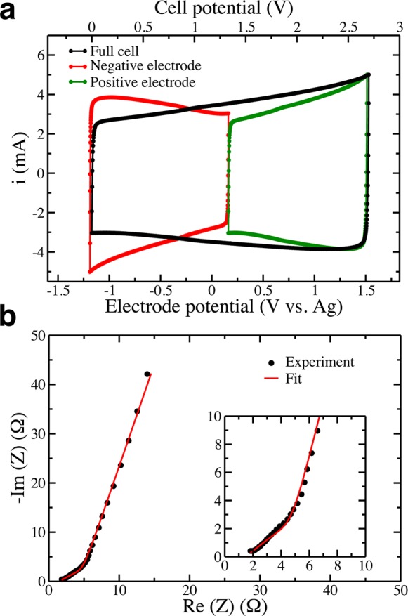
(a) Cyclic voltammograms and (b) Nyquist plot of the impedance of a supercapacitor cell assembled with two electrodes based on 0.9 nm average pore size carbide-derived carbon (CDC), in an electrolyte composed of BMIM-PF6 dissolved in ACN. Electrode potentials are reported with respect to a Ag reference electrode. For the cyclic voltammograms the potential scan rate is 5 mV s–1, while for the impedance the potential is set to 0.4 V/Ag, and frequencies are sampled from 200 kHz to 10 mHz (inset: zoom of the high-frequency region).
In-Pore Resistivity and Diffusion Coefficients
The Nyquist plot of the impedance, recorded at 0.4 V with respect to a Ag reference electrode, is shown in Figure 1b. It corresponds again to a typical capacitive behavior, with a linear trend for both the real and imaginary parts of the capacitance in the intermediate frequency range, followed by a sharp (quasi-vertical) increase in the imaginary part of the impedance at low frequency. By fitting the data using de Levie’s transmission line model22,23 (Figure S1), it is possible to extract a resistivity for the electrolyte confined inside the porous carbons. A value of 60 Ω cm is obtained at 0.4 V/Ag which is in the same range as that of the bulk electrolyte (around 27 Ω cm at 298 K). The small value obtained seems to indicate a fast ionic transport inside the electrodes. Impedance diagrams were recorded at other potentials under stationary conditions, yielding similar values for the in-pore electrolyte resisitivity (Figure 2), apparently showing that the transport mechanism is not affected by the change of composition in the electrode within the potential range explored.
Figure 2.
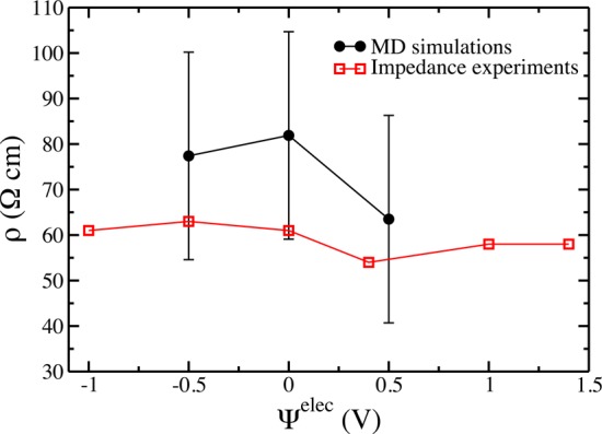
Variation of the calculated and experimental in-pore resistivities with the electrode potential.
Although knowing the in-pore resistivity brings very useful information, it cannot straightforwardly be translated into microscopic-based quantities such as residence times or diffusion coefficients. Indeed, the resistivity is the inverse of the conductivity, which is a collective quantity. Unlike the recent example of the diffusion of hydrocarbons in nanoporous kerogens,32 strong correlations are expected between the ions due to their strong Coulombic interactions. The conductivity depends on the displacement of all the ions inside the pores and thus on their concentrations and the volume they occupy. In molecular dynamics simulations, it is possible to calculate the mean-square displacement (MSD) of each ion i individually from the difference of its position ri between two times t1 and t2 along a trajectory,
| 2 |
Here we will consider the displacements along the x and y coordinates only, and we note the corresponding quantities as δri⊥ and ri, because the electrode/electrolyte interface is perpendicular to the z coordinate. Ensemble averages of the MSD of the cations inside the electrode for the various potentials are shown in Figure 3a; similar plots are obtained for the anions. Unlike bulk liquids, in which a linear régime is quickly reached, they show nontrivial features. Due to the disordered structure of the porous carbon, which can be seen as a sponge with strongly interconnected pores, the ions sample various environments as they diffuse33 and thus have different characteristic MSDs. For short times, this leads to a nonlinear variation of the MSD with time that is typical of a subdiffusive behavior, unlike in the bulk liquid where the variation is almost immediately linear. Inside the pores, displacements >40 Å2 need to be reached before the linear régime occurs. A typical length scale of the carbon structure is its average pore size, which is p̅ ≈ 9 Å in the present case.28 The associated displacement, taking into account the dimensionality of the MSD, is ≈54 Å2, which is shown as a horizontal dashed line on Figure 3a. Therefore, the linear régime likely corresponds to a diffusion process from pore to pore. It is possible to calculate an associated effective diffusion coefficient using
| 3 |
where d = 2 is the dimensionality
of the MSD and SCi(t) = 1 if
the ion remains continuously inside the electrode between 0 and t, while SC(t) = 0 otherwise.
The brackets denote the ensemble average over all the ions of type
α. Ψelec is the potential of the electrode;
it is not an absolute potential since we can only control the applied
potential ΔΨ in the simulations.14,29 We set  by convention.
Figure 3.

(a) MSD versus time for the cations inside electrodes held at various potentials. The dashed line corresponds to a length scale characteristic of the average pore size. (b) Variation of the in-pore effective diffusion coefficients with the electrode potential. In the bulk electrolyte the diffusion coefficients of the ions are Dbulk ∼ 10–5 cm2 s–1 at 298 K. (c) Variation of the in-pore ionic concentrations (per gram of carbon electrode) with the electrode potential.
The results for both ion types are shown in Figure 3b. The in-pore effective diffusion coefficients are lower than the bulk diffusion coefficients by slightly more than 1 order of magnitude (Dbulk ∼ 10–5 cm2 s–1 for the ions at 298 K).34 They show a nontrivial potential dependence, which is difficult to analyze given the strong composition changes occurring inside the electrodes with the applied potentials, which are shown in Figure 3c. Indeed, the screening of the Coulombic interaction allows for the formation of a superionic state in which ions with similar charges can approach much closer than in the bulk electrolyte.18,35 For example, at −1 V there is a ratio of 6.6 between the concentrations of cations and anions. If we focus on the positive potentials side, the diffusion coefficients of the anions progressively decrease, as a result of the stronger attraction to the surface, which will be quantified in the next section. On the contrary, cations diffuse faster for low potentials because they are less confined.33 However, their diffusion coefficients reach a maximum before decreasing again. This is probably due to a steric effect: At 1 V, the surfaces of the pores are now filled with anions, resulting in a limitation of the accessible volume for cations.
We do not observe a variation of the diffusion coefficients with potential by several orders of magnitude, as was recently reported by Kondrat et al.6 In their case, the simulated system consisted in a pure ionic liquid electrolyte and an ideal slit pore electrode. They observed drastic changes in structure/composition of the adsorbed fluid with the applied potential: Slowly diffusing ordered structures were formed by the ions at null and large potentials, while at intermediate voltages they adopted a disordered structure in which their diffusion coefficients were even larger than in the bulk electrolyte. In our case the ions are less concentrated in the electrode due to the presence of solvent molecules, and the complex topology of the carbon electrodes does not allow for the formation of long-range ordered structures. As a consequence, the structural changes, and hence the diffusion coefficients variations, are much more continuous for the electrode potentials we consider.
At first sight, the decrease in the diffusion coefficients with respect to the bulk is large compared to the measured in-pore resistivity (which is smaller than the bulk one by a factor of 2 only). Indeed, the electrical conductivity is generally estimated from the diffusion coefficients using the Nernst–Einstein equation. However, it is valid for strongly diluted electrolytes only. Here the liquid inside the pores has a high concentration of ions, and the accessible volume Velec inside the electrodes, and not the total volume of the electrode, should be taken into account36 (Figure S3). In addition, for nonzero potentials, the quantities of adsorbed cations/anions strongly differ. We therefore need to compute the electrical conductivity directly, using
| 4 |
where the two sums run respectively over the number of time intervals Nt used to calculate the autocorrelation function and all the ions N in the simulation cell, qi is the charge of ion i, β = 1/kBT with kB the Boltzmann constant and T the temperature. Velec is the volume occupied by the ions inside the electrode. SDi is a discontinuous presence function, which takes a value of 1 if an ion is present in the electrode at time tj and 0 otherwise.
Unlike the diffusion coefficients for which it is possible to average over the ions, the conductivity is a collective quantity. The statistics for the ensemble average in eq 4 are hence much smaller, even when performing long simulations. A well-defined linear régime could therefore be observed for the lower applied potentials only (Figure S4), from which we could determine in-pore resistivities ρ = 1/σ. The corresponding values are compared to the experimental ones in Figure 2. The agreement is good, which shows that the dynamics of the ions is accurate in the simulations.
Adsorption Lifetimes
In our previous work,33 we have shown that it is possible to characterize the degree of confinement of the ions inside the electrodes. We identified four different adsorption types, defined as edge, plane, hollow, and pocket sites upon increasing the coordination of the molecular species by carbon atoms from the electrode. In ACN-based electrolytes, the ions are mostly adsorbed on plane sites,33 so that we will focus on the dynamics of adsorption in these sites.
We define a plane-adsorption characteristic function hCi(t). It equals one if a given ion i remains continuously adsorbed on a plane site from time 0 to t and zero otherwise. The kinetics of departure from plane-adsorption sites can then be quantified by the time–correlation function:
| 5 |
Here also the brackets denote the ensemble average over all ions of type α. The functions obtained for the anions are shown in Figure 4. They provide the average fraction of ions remaining in plane adsorption sites for at least a time t, which is an interesting information for interpreting the diffusion coefficients. At 0 V, the typical adsorption time is of 150 ps. At negative potentials, the anions play the role of co-ions. The small fraction of ions which can adsorb on the surface leave it very quickly, on the picosecond time scale. On the contrary, at positive potentials, the adsorption lifetime grows very strongly, reaching 1 ns and beyond, thereby explaining the corresponding slow-down for the in-pore diffusion coefficient.
Figure 4.
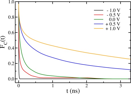
Time–correlation function of the plane-adsorption characteristic function for the anions, at various electrode potentials.
Desolvation Dynamics
A last process worth examining from the dynamical point of view is the desolvation of the ions inside the pores. Indeed, as anticipated from the experimental point of view,10,12 simulations have shown that organic ions partially desolvate inside nanoporous carbons, the extent of desolvation being correlated with the degree of confinement.33,37,38
In order to study how fast the desolvation process occurs, we have isolated the following events during our simulations: (i) entrance of an ion inside the electrode; (ii) switch of an ion from an edge to a plane site, and (iii) switch of an ion from a plane to a hollow site. For each of the observed event, we reset the clock at t* when it occurs. We monitor the solvation number for times before and after the event and average it over all the events. The results are displayed in Figure 5. The desolvation is moderate upon entrance inside the pores, with a coordination number switching on average from 9.5 to 8.5. The effect is larger when an ions changes of confinement site (loss of two solvent molecules when passing from an edge to a plane or from a plane to a hollow site). Note that the average solvation number measured 25 ps after the adsorption on a plane site (7.5) does not match exactly with the one calculated 25 ps before the switch from a plane to a hollow site (6.5) because the plane sites span a wide range of degrees of confinement.33 For each of the events, the change of solvation number occurs on a very short time scale, namely between 1 and 3 ps. This shows that for these organic ions the solvation by the ACN is not very strong and that it is not a limiting step for the overall adsorption process.
Figure 5.
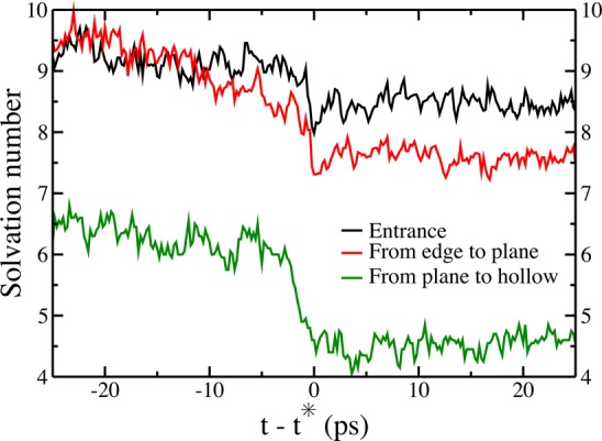
Average coordination number of the anions during typical events inside an electrode held at 1 V (black: entrance of an anion inside the electrode; red: switch from an edge to a plane site; green: switch from a plane to a hollow site). The clock is set to t* = 0 when the event occurs in the simulation.
Conclusion
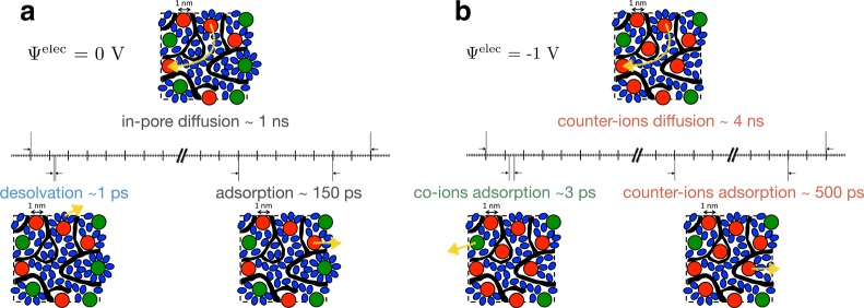
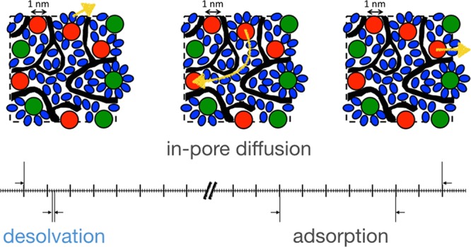
The simulated capacitances and in-pore resistivities agree almost quantitatively with the experimental ones. We can therefore rely on the microscopic description of both the structure and the transport of the electrolyte inside the pores. In particular, we can extract some characteristic times for the dynamic processes described in Figures 3, 4, and 5. These are summarized on Figure 6a for a system at null potential. The shortest time is associated with desolvation (∼1 ps), while the characteristic adsorption time is of ≈150 ps. The in-pore characteristic diffusion time was extracted from Figure 3a as the time such that the MSDs of the ions equal the value associated with the characteristic length scale of the porous network. We obtain a typical value of 1 ns. This means that during its diffusion from one pore to another, an ion will experience several surface adsorption/desorption events, i.e., intermittent dynamics.39 Each of these events will be accompanied by the loss/gain of several solvent molecules in its solvation shell.
Figure 6.
Summary of the various characteristic times extracted from the simulations for electrodes held at 0 V (a) and −1 V (b). The black regions represent the porous carbon; red, green, and blue spheres/ellipses represent adsorbed cations, anions, and acetonitrile molecules, respectively. The characteristic dynamic processes are shown with yellow arrows.
In electrified pores, counterion desorption events become much longer-lived, for example, the characteristic time shown on Figure 6b for cations at Ψelec = −1 V is of ∼500 ps. On the contrary, the few co-ions which approach the surface desorb very quickly. As a consequence, the diffusion of the counterions from pore to pore is noticeably slowed down, by a factor of approximatively 4 at −1 V.
In conclusion, we have shown that the molecular dynamics of ions inside electrified nanoporous electrodes is characterized by a hierarchy of time scales. From the practical point of view, the diffusion is slowed down by 1 order of magnitude compared to the bulk electrolyte due to confinement effects and by an additional factor of 4 for counterions when a potential is applied due to the strong electrostatic attraction with the pore walls. However, these numbers remain sufficiently high for ensuring fast enough charging processes10,16 for efficient supercapacitors. Combined with computational screening methods which can efficiently predict new electrolytes with enhanced properties,40 molecular dynamics simulations provide an accurate way for optimizing simultaneously the energy and power densities of supercapacitors.
Acknowledgments
The research leading to these results has received funding from the European Research Council under the European Union’s Seventh Framework Programme (FP/2007-2013)/ERC grant agreement no. 102539. This work was supported by the French National Research Agency (Labex STORE-EX: grant ANR-10-LABX-0076). We are grateful for the computing resources on JADE and OCCIGEN (CINES, French National HPC) obtained through the projects x2014096728 and x2015096728. We acknowledge PRACE for awarding us access to resource CURIE based in France at TGCC.
Supporting Information Available
The Supporting Information is available free of charge on the ACS Publications website at DOI: 10.1021/jacs.5b07416.
Equivalent circuit (transmission line model) of a porous carbon electrode. Snapshot of the simulation cell. Accessible volume for the electrolyte species inside the electrodes. MSDs for the calculation of the in-pore resistivities (PDF)
The authors declare no competing financial interest.
Supplementary Material
References
- Marry V.; Dubois E.; Malikova N.; Breu J.; Haussler W. J. Phys. Chem. C 2013, 117, 15106–15115. 10.1021/jp403501h. [DOI] [Google Scholar]
- Chiavazzo E.; Fasano M.; Asinari P.; Decuzzi P. Nat. Commun. 2014, 5, 3565. 10.1038/ncomms4565. [DOI] [PMC free article] [PubMed] [Google Scholar]
- Wilson M.; Madden P. A. J. Am. Chem. Soc. 2001, 123, 2101–2102. 10.1021/ja003737x. [DOI] [PubMed] [Google Scholar]
- Hummer G.; Rasaiah J. C.; Noworyta J. P. Nature 2001, 414, 188–190. 10.1038/35102535. [DOI] [PubMed] [Google Scholar]
- Chaban V. V.; Prezhdo O. V. ACS Nano 2014, 8, 8190–8197. 10.1021/nn502475j. [DOI] [PubMed] [Google Scholar]
- Kondrat S.; Wu P.; Qiao R.; Kornyshev A. A. Nat. Mater. 2014, 13, 387–393. 10.1038/nmat3916. [DOI] [PubMed] [Google Scholar]
- Conway B. E.Electrochemical Supercapacitors: Scientific Fundamentals and Technological Applications; Kluwer: New York, 1999. [Google Scholar]
- Simon P.; Gogotsi Y. Nat. Mater. 2008, 7, 845–854. 10.1038/nmat2297. [DOI] [PubMed] [Google Scholar]
- Béguin F.; Presser V.; Balducci A.; Frackowiak E. Adv. Mater. 2014, 26, 2219–2251. 10.1002/adma.201304137. [DOI] [PubMed] [Google Scholar]
- Chmiola J.; Yushin G.; Gogotsi Y.; Portet C.; Simon P.; Taberna P. L. Science 2006, 313, 1760–1763. 10.1126/science.1132195. [DOI] [PubMed] [Google Scholar]
- Richey F. W.; Dyatkin B.; Gogotsi Y.; Elabd Y. A. J. Am. Chem. Soc. 2013, 135, 12818. 10.1021/ja406120e. [DOI] [PubMed] [Google Scholar]
- Tsai W.-Y.; Taberna P.-L.; Simon P. J. Am. Chem. Soc. 2014, 136, 8722–8728. 10.1021/ja503449w. [DOI] [PubMed] [Google Scholar]
- Forse A. C.; Griffin J. M.; Merlet C.; Bayley P. M.; Wang H.; Simon P.; Grey C. P. J. Am. Chem. Soc. 2015, 137, 7231–7242. 10.1021/jacs.5b03958. [DOI] [PMC free article] [PubMed] [Google Scholar]
- Merlet C.; Pean C.; Rotenberg B.; Madden P. A.; Simon P.; Salanne M. J. Phys. Chem. Lett. 2013, 4, 264–268. 10.1021/jz3019226. [DOI] [PubMed] [Google Scholar]
- Vatamanu J.; Vatamanu M.; Bedrov D. ACS Nano 2015, 9, 5999–6017. 10.1021/acsnano.5b00945. [DOI] [PubMed] [Google Scholar]
- Pean C.; Merlet C.; Rotenberg B.; Madden P. A.; Taberna P.-L.; Daffos B.; Salanne M.; Simon P. ACS Nano 2014, 8, 1576–1583. 10.1021/nn4058243. [DOI] [PubMed] [Google Scholar]
- He Y.; Huang J.; Sumpter B. G.; Kornyshev A. A.; Qiao R. J. Phys. Chem. Lett. 2015, 6, 22–30. 10.1021/jz5024306. [DOI] [PubMed] [Google Scholar]
- Merlet C.; Rotenberg B.; Madden P. A.; Taberna P.-L.; Simon P.; Gogotsi Y.; Salanne M. Nat. Mater. 2012, 11, 306–310. 10.1038/nmat3260. [DOI] [PubMed] [Google Scholar]
- Pean C.; Daffos B.; Merlet C.; Rotenberg B.; Taberna P.-L.; Simon P.; Salanne M. J. Electrochem. Soc. 2015, 162, A5091–A5095. 10.1149/2.0151505jes. [DOI] [Google Scholar]
- Largeot C.; Portet C.; Chmiola J.; Taberna P. L.; Gogotsi Y.; Simon P. J. Am. Chem. Soc. 2008, 130, 2730–2731. 10.1021/ja7106178. [DOI] [PubMed] [Google Scholar]
- Portet C.; Taberna P.-L.; Simon P.; Flahaut E.; Laberty-Robert C. Electrochim. Acta 2005, 50, 4174–4181. 10.1016/j.electacta.2005.01.038. [DOI] [Google Scholar]
- de Levie R. Electrochim. Acta 1963, 8, 751–780. 10.1016/0013-4686(63)80042-0. [DOI] [Google Scholar]
- de Levie R. J. Electroanal. Chem. Interfacial Electrochem. 1989, 261, 1–9. 10.1016/0022-0728(89)87121-9. [DOI] [PMC free article] [PubMed] [Google Scholar]
- Zhao W.; Leroy F.; Heggen B.; Zahn S.; Kirchner B.; Balasubramanian S.; Muller-Plathe F. J. Am. Chem. Soc. 2009, 131, 15825–15833. 10.1021/ja906337p. [DOI] [PubMed] [Google Scholar]
- Roy D.; Maroncelli M. J. Phys. Chem. B 2010, 114, 12629–12631. 10.1021/jp108179n. [DOI] [PubMed] [Google Scholar]
- Edwards D. M.; Madden P.; McDonald I. Mol. Phys. 1984, 51, 1141–1161. 10.1080/00268978400100731. [DOI] [Google Scholar]
- Merlet C.; Salanne M.; Rotenberg B.; Madden P. A. Electrochim. Acta 2013, 101, 262–271. 10.1016/j.electacta.2012.12.107. [DOI] [Google Scholar]
- Palmer J. C.; Llobet A.; Yeon S.-H.; Fisher J. E.; Shi Y.; Gogotsi Y.; Gubbins K. E. Carbon 2010, 48, 1116–1123. 10.1016/j.carbon.2009.11.033. [DOI] [Google Scholar]
- Reed S. K.; Lanning O. J.; Madden P. A. J. Chem. Phys. 2007, 126, 084704. 10.1063/1.2464084. [DOI] [PubMed] [Google Scholar]
- Vatamanu J.; Borodin O.; Smith G. D. J. Am. Chem. Soc. 2010, 132, 14825–14833. 10.1021/ja104273r. [DOI] [PubMed] [Google Scholar]
- Luque N. B.; Schmickler W. Electrochim. Acta 2012, 71, 82–85. 10.1016/j.electacta.2012.03.083. [DOI] [Google Scholar]
- Falk K.; Coasne B.; Pellenq R.; Ulm F.-J.; Bocquet L. Nat. Commun. 2015, 6, 6949. 10.1038/ncomms7949. [DOI] [PMC free article] [PubMed] [Google Scholar]
- Merlet C.; Pean C.; Rotenberg B.; Madden P. A.; Daffos B.; Taberna P.-L.; Simon P.; Salanne M. Nat. Commun. 2013, 4, 2701. 10.1038/ncomms3701. [DOI] [PubMed] [Google Scholar]
- Chaban V. V.; Voroshylova I. V.; Kalugin O. N.; Prezhdo O. V. J. Phys. Chem. B 2012, 116, 7719–7727. 10.1021/jp3034825. [DOI] [PubMed] [Google Scholar]
- Kondrat S.; Kornyshev A. A. J. Phys.: Condens. Matter 2011, 23, 022201. 10.1088/0953-8984/23/2/022201. [DOI] [PubMed] [Google Scholar]
- Ori G.; Villemot F.; Viau L.; Vioux A.; Coasne B. Mol. Phys. 2014, 112, 1350–1361. 10.1080/00268976.2014.902138. [DOI] [Google Scholar]
- Ohkubo T.; Konishi T.; Hattori Y.; Kanoh H.; Fujikawa T.; Kaneko K. J. Am. Chem. Soc. 2002, 124, 11860–11861. 10.1021/ja027144t. [DOI] [PubMed] [Google Scholar]
- Ohba T.; Kaneko K. J. Phys. Chem. C 2013, 117, 17092–17098. 10.1021/jp405479y. [DOI] [PubMed] [Google Scholar]
- Levitz P.; Bonnaud P. A.; Cazade P.-A.; Pellenq R. J. M.; Coasne B. Soft Matter 2013, 9, 8654–8663. 10.1039/c3sm51940f. [DOI] [Google Scholar]
- Schütter C.; Husch T.; Korth M.; Balducci A. J. Phys. Chem. C 2015, 119, 13413–13424. 10.1021/acs.jpcc.5b02113. [DOI] [Google Scholar]
Associated Data
This section collects any data citations, data availability statements, or supplementary materials included in this article.


