Abstract
Deep-tissue penetration is highly required in in vivo optical bioimaging. We synthesized a type of red emissive fluorophore BT with aggregation-induced emission (AIE) property. BT molecules were then encapsulated with amphiphilic polymers to form nanodots, and a large two-photon absorption (2PA) cross-section of 2.9 × 10⁶ GM at 1040 nm was observed from each BT nanodot, which was much larger than those at the wavelengths of 770 to 860 nm. In addition, 1040 nm light was found to have better penetration and focusing capability than 800 nm light in biological tissue, according to the Monte Carlo simulation. The toxicity and tissue distribution of BT nanodots were studied, and they were found to have good biocompatibility. BT nanodots were then utilized for in vivo imaging of mouse ear and brain, and an imaging depth of 700 μm was obtained with the femtosecond (fs) excitation of 1040 nm. The red emissive AIE nanodots with high 2PA efficiency at 1040 nm would be useful for deep-tissue functional bioimaging in the future.
OCIS codes: (160.2540) Fluorescent and luminescent materials, (160.4236) Nanomaterials, (170.3880) Medical and biological imaging, (180.2520) Fluorescence microscopy, (180.4315) Nonlinear microscopy, (190.4180) Multiphoton processes
1. Introduction
Bioimaging is of great importance to the development and clinical applications of medicine [1].Among various techniques, X-ray, Computed Tomography (CT), ultrasonic imaging and Magnetic Resonance Imaging (MRI) are the most popular ones. However, X-ray and CT have radiation damage to the biological tissues [2], and the resolution and contrast of ultrasonic imaging and MRI are not well satisfying [3,4]. Optical bioimaging is a very promising technique, due to its high spatial resolution, abundant information source, low damage to the bio-samples and feasibility to combine with other techniques [5]. However, the depth of optical bioimaging is usually a problem, due to water absorption and light scattering in biological tissues [6]. Two-photon luminescence (2PL) imaging, with its inherence of lower autofluorescence, reduced out-of-focus photobleaching, intrinsically high three-dimensional resolution, and deep-tissue penetration capability, is a favored technology in in vivo optical bioimaging [7]. Thus, the fluorescent labels with high 2PL brightness, good stability and biocompatibility are highly required in 2PL imaging [8].
To date, various fluorescent probes, including small organic dyes [9], fluorescent proteins [10], inorganic semiconductor quantum dots (QDs) [11] and metal nanoparticles [12,13] have been exploited for 2PL bioimaging. However, these materials have some drawbacks, such as limited fluorescence stability of organic dyes and fluorescent proteins under long-term laser excitation [14–16], potential toxicity and irregular blinking of QDs [17], and photo-thermal damage suffered by metal nanoparticles [18]. To improve the photobleaching resistance, as well as brightness of organic dyes, one method is to increase their concentration. However, most organic dyes suffer from a severe aggregation-caused quenching (ACQ) effect [19], which means their fluorescence is quenched at high molecule concentrations. Aggregation-induced emission (AIE) luminogens can overcome this problem by restricting the non-radiative pathways [20]. Nanoparticles doped with AIE luminogens possess high brightness [19], good chemical stability and photostability, as well as biocompatibility, which makes them promising labels for 2PL bioimaging [21,22].
In this paper, we synthesized a type of red emissive organic fluorophore, which is called 3, 5-dimethyl-8-[4-(1,2,2-triphenylvinyl)phenyl-1-yl]-4,4-difluoro-4-bora-3a,4a-diaza-s-indacene (BODIPY-TPE or BT), and its AIE feature was characterized in THF/water mixtures. Small BT molecules were encapsulated into nanomicelles with a modified nanoprecipitation procedure [23,24]. The one-photon and two-photon behaviors of the BT nanodots were characterized, and a 2PA cross-section of 2.9 × 10⁶ GM was observed at 1040 nm, which is much higher than those at the wavelengths ranging from 770 to 860 nm. In addition, we studied the propagation of 800 nm and 1040 nm laser beams in biological tissue, with Monte Caro simulation [25]. 1040 nm laser beam was found to have better penetrating and focusing capability in biological tissues than the conventionally used 800 nm laser beam, due to less tissue scatting, which would be more helpful for deep-tissue imaging. The toxicity and tissue distribution of BT nanodots were studied by imaging the organs of mice at different time points post injection of BT nanodots, and they were found to have good biocompatibility. By utilizing a 1040 nm fs laser (150 fs, 50 MHz), BT nanodots were further utilized for in vivo imaging of blood vessels of mouse ear and brain. High contrast 3D images were constructed vividly, and the imaging depth could reach 700 μm in the mouse brain. The combination of red emission, high 2PA cross-section from AIE nanodots, and efficient 1040 nm fs laser excitation would be helpful to deep-tissue functional in vivo imaging in the future.
2. Methods and experiments
2.1 Materials and instruments
The BODIPY-TPE fluorogen was prepared following our previously published protocol [26]. DSPE-mPEG5000 was purchased from Creative PEGWorks, Inc. Other chemical reagents, which were not specially mentioned, were purchased from Sigma Inc. Deionized (DI) water was used in all the experiments. The extinction spectra were recorded on a UV-vis scanning spectrophotometer (UV-2550, Shimadzu, Japan) and the photoluminescence (PL) spectra were obtained by a fluorescence spectrophotometer (F-2500, HITACHI, Japan). The morphologies of BT nanodots were taken by a transmission electron microscope (TEM, JEM-1200EX, JEOL, Japan) operating at 160 kV in bright-field mode.
2.2 Preparation and characterization of BT nanodots
BT nanodots were synthesized via a modified nanoprecipitation procedure [23,24], and the schematic illustration was shown in Fig. 1(a). Briefly, 250 μL of BT solution in chloroform (1 mg/mL) and 100 μL of DSPE-mPEG5000 solution in chloroform (10 mg/mL) were added into a flask to form the mixture. After sonicated for several minutes, the mixture was dried under vacuum in a rotary evaporator at 65°C to remove the chloroform. 200 μL of deionized water was then added into the flask and the solution was sonicated. Finally, an optically clear and chemically stable suspension containing BT nanodots was prepared.
Fig. 1.
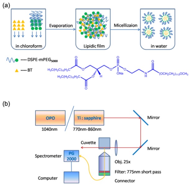
(a) A scheme illustrating the synthesis process of BT nanodots. (b) Schematic illustration of the setup for 2PA cross-section measurements.
Two-photon action cross-section (ηδ), which is the product of 2PA cross-section (δ) and fluorescence quantum yield (η), is a parameter describing how bright a fluorophore is under two-photon excitation [27]. To compare the two-photon fluorescence efficiency of BT nanodots, under conventional 800 nm fs excitation and our proposed 1040 nm fs excitation, the δ and ηδ of the nanodots were measured via a two-photon induced fluorescence method [28,29]. A mode-locked Ti:Sapphire fs laser (200 fs, 76 MHz) was used as the excitation source for the measurement of δ at wavelengths from 770 nm to 860 nm, and an amplified output of a large-mode-area ytterbium-doped photonic crystal fiber (PCF) oscillator (1040 nm, 150 fs, 50 MHz) was adopted for the measurement of δ at 1040 nm. The fs laser beam was focused onto the sample in a cuvette by a lens (f = 40 mm), and the focus was near the edge of the cuvette to minimize self-absorption of 2PL signal by the sample. The 2PL signal from the sample was collected by an objective (20 × , NA = 1.00), which was perpendicular to the laser beam propagation direction, filtered by a 775 nm short-pass optical filter, and directed into a spectrometer (PG2000, Ideaoptics Instruments), as shown in Fig. 1(b). Rhodamine B (RhB) in methanol was used as the reference [30]. The 2PA cross-section of BT nanodots was calculated according to the following equation [29]:
| (1) |
where δ is the 2PA cross-section, F is the 2PL intensity, η is the fluorescence quantum yield (QY), c is the molar concentration, n is the refractive index of the solvent, and the subscripts 0 and 1 represent the reference (RhB in methanol) and the sample (BT nanodots in water).
2.3 Monte Carlo simulation of the focal spots of 1040 nm and 800 nm laser beams in biological tissue
The penetration and focus capability of the excitation laser beam in biological tissue is dependent on the scattering and absorption of light in the tissue, and previously, 1040 nm light has been proved to have better penetration depth than 800 nm light [31]. Vectorial electric field Monte Carlo (EMC) simulation, which can be used to simulate the scattering and absorption of the electric field, was applied to generate the intensity distribution of focal spots in biological tissue at some typical depths for our experiment. The brain was assumed to be a tissue-like phantom containing scattering beads of 1 μm diameter at a concentration of 0.1044 spheres/μm3, which resembled the scattering property of the gray matter of the cortex [25, 31–33]. 1040 nm and 800 nm were chosen as the simulation wavelengths.
2.4 Biodistribution and clearance of BT nanodots in mice
All the animal experiments were conducted in accordance with the rules of Zhejiang University Animal Study Committee for the care and use of laboratory animals in research. The animal housing area was kept at 24°C with a 12 hour light/dark cycle, and animals were fed with water and standard laboratory fodder. 8-week-aged female BALB/c mice were used for in vivo imaging. The mice were intravenously injected with 200 μL PBS (1 × ) dispersion containing BT nanodots via their tail veins. The mice were put down at various time points after the injection, and their major organs, including heart, liver, spleen, lungs and kidney, were taken out through surgery, washed with PBS (1 × ), and were then immersed in 4% formaldehyde solution. The organs of mice at different time points were imaged on a Maestro in vivo optical imaging system (CRI, Inc. Woburn, MA). The excitation wavelengths were centered at 523 nm and the images were captured with a constant exposure time of 200 ms for all the samples.
2.5 In vivo imaging of ear blood vessels of mice
8-week-aged female BALB/c mice were used for in vivo imaging. The mice were anesthetized with an intraperitoneal injection of 5% trichloroacetaldehyde hydrate solution, and 200 μL PBS (1 × ) dispersion containing BT nanodots was intravenously injected into the mice via their tail veins. The mice were placed on a transparent Petri dish with one ear stuck on it, so the area could be immobilized for in vivo microscopic imaging.
An upright confocal microscope (Olympus, BX61W1-FV1000) equipped with the 1040 nm fs laser (pulse width: 150 fs, repetition rate: 50 MHz, average output power: 2 W), was used for 2PL microscopic imaging of the ear blood vessels of mice. A long work distance water-immersion objective lens (20 × , NA = 1.00, work distance = 2.2 mm) was used to focus the fs laser beam onto the water-immersed earlobe of mice. The 2PL signals were collected with the same objective, through a 590 nm long pass filter, and collected by an external photomultiplier tube (PMT) via non-descanned detection (NDD).
2.6 In vivo imaging of brain blood vessels of mice
8-week-aged female BALB/c mice were used for in vivo brain imaging. The mice were anesthetized with an intraperitoneal injection of 5% trichloroacetaldehyde hydrate solution and their skulls were opened up through microsurgery. A small metal ring with a handle was mounted onto the opened brain of each mouse. Then a round thin cover glass slide was embedded in the ring and adhered to the mouse through dental cement. This could help to protect the brain from the damage of surroundings, as well as offer a cranial window for microscopic imaging. The metal ring was then connected to a metal plated with a handle, via handle-handle connection. As the metal plate was very heavy, this configuration could help to keep the mouse head immobilized during the whole imaging process. The mice were then intravenously injected with 200 μL of BT nanodots in 1 × PBS dispersion via their tail veins.
In vivo 2PL imaging of brain blood vessels was conducted on the same two-photon scanning microscope system (Olympus, BX61W1-FV1000; objective: 20 × , NA = 1.05, work distance = 2.2 mm; wavelength of excitation fs laser: 1040 nm). The 2PL signals were collected with the same objective, through a 590 nm long pass filter, and collected by an external photomultiplier tube (PMT) via non-descanned detection (NDD).
3. Results and discussion
3.1 Molecular structure and AIE property of BT
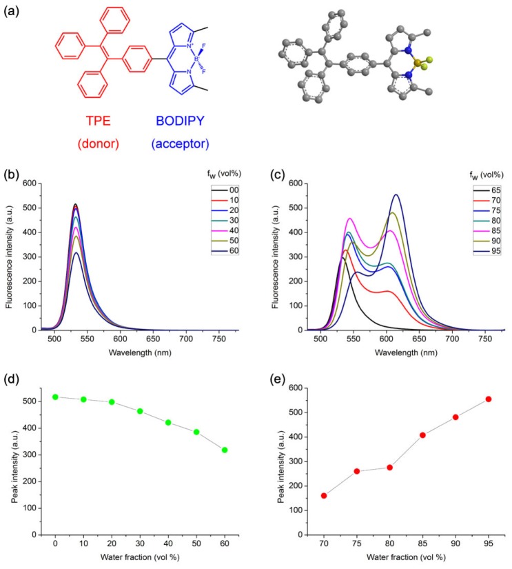
The molecular structure of BODIPY-TPE (BT) was shown in Fig. 2(a). It was composed of tetraphenylethene (TPE) as the donor and boron dipyrromethene (BODIPY) as the acceptor, and this donor-acceptor structure would be helpful to improving the fluorescence intensity of dye [21, 34]. BODIPY derivatives have strong absorption, sharp fluorescence bands, high quantum yield and large 2PA cross-section [35], and the propeller-shaped TPE was commonly used in AIE compounds due to the restriction of intramolecular rotation (RIR) in its structure [36].
Fig. 2.
(a) Chemical structure and molecular geometry of BT. (b) and (c) Fluorescence spectra of BT in THF/water mixtures with different volume fractions of water (fw), (b) fw = 0 to 60 vol%, (c) fw = 70 to 95 vol%. (d) and (e) Plot of peak fluorescence intensity of BT versus fw in THF/water mixtures, (d) fw = 0 to 60 vol%, (e) fw = 70 to 95 vol%. [BT] = 10 μM; excitation wavelength λex = 420 nm.
The AIE behavior of BT was studied by measuring the fluorescence (FL) spectra of BT in THF/water mixtures with different volume fractions of water (fw), which enabled fine-tuning of the solvent polarity and the aggregation extent of BT molecules. As shown in Fig. 2(b) and 2(d), with increasing fw in THF/water mixtures from 0 to 60 vol%, the fluorescence intensity around 530nm (giving green fluorescence) decreased, which was attributed to a typical twisted intramolecular charge transfer (TICT) effect, resulting from the increase of the solvent polarity [37]. Upon continuing increasing fw from 70 to 95 vol%, fluorescence with wavelength longer than 600 nm (giving red fluorescence) appeared and its intensity increased dramatically, as shown in Fig. 2(c) and 2(e). It might come from the restriction of intramolecular rotation and consequential suppression of non-radiative path ways of BT molecules when aggregated into nanoparticles, and this was a typical indication of the aggregation-induced emission enhancement (AEE) feature of BT molecules [38].
3.2 One- and two-photon properties of BT nanodots
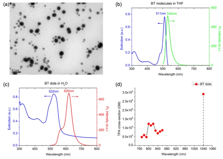
The morphology of BT nanodots was visualized by TEM. As shown in Fig. 3(a), they had a spherical shape, with a mean diameter of 52 nm.
Fig. 3.
(a) A representative TEM image of BT nanodots. Scale bar: 200 nm . (b) Extinction and 1PL spectra of BT molecules in THF, λex = 420nm. (c) Extinction and 1PL spectra of BT nanodots in aqueous dispersion, λex = 420nm. (d) 2PA cross-section of BT nanodots at various wavelengths.
The extinction and one-photon luminescence (1PL) spectra of BT molecules in THF, as well as aqueous dispersion of BT nanodots, were shown in Fig. 3(b) and 3(c). For BT in THF, it had an absorption peak near 511 nm and the emission spectrum was centered at 532 nm (giving green fluorescence), with a small Stokes shift of 21 nm (Fig. 3(b)). For BT nanodots, the absorption peak was slightly shifted to 522 nm, while the emission peak was distinctly red-shifted to 620 nm (giving red fluorescence), resulting in a large Stokes shift of 98 nm (Fig. 3(c)). Fluorescent probe with large Stokes shift is very beneficial for bioimaging, as its emission signals could be easily extracted from the excitation light via an optical filter, which could provide a better signal-to-noise ratio for the image [39]. Considering DSPE-mPEG5000 molecules had no absorption in the visible wavelength range, the slight red-shifted absorption peak of BT nanodots might be induced by the increasing surrounding refractive index of BT in the nanomicelles, and the lift up of the extinction in the short-wavelength range was due to the light scattering from BT nanodots. The large emission peak red-shift of BT nanodots arose from the restriction of intramolecular rotation of BT molecules, and this would be another indication of the AIE feature of BT molecules [24]. The red emission was favored in deep-tissue bioimaging, due to its less scattering in biological tissues [40].
The 2PA cross-sections (δ) of BT nanodots at 770 – 860 nm and 1040 nm were shown in Fig. 3(d). The δ of BT nanodots were all above 4 × 10⁵ GM, illustrating BT nanodots possess good 2PA efficiency. The δ at 1040 nm was about 2.9 × 10⁶ GM, and it was much larger than those at 770 – 860 nm. Thus, a 1040 nm fs laser could achieve better 2PL excitation of BT nanodots than commonly used Ti:Sapphire fs laser, whose wavelength is tunable from 770 nm to 860 nm. In addition, the quantum yield (η) of BT nanodots in aqueous dispersion was measured to be 5.0%, via a widely used comparative method [41]. So the two-photon action cross-section (ηδ) of BT nanodots at 1040 nm was calculated to be 1.5 × 10⁵ GM, which was much higher than some commercial organic dyes (e.g. ηδ of RhB in MeOH is 23 GM at 1040 nm), indicating the high 2PL brightness of BT nanodots under the fs excitation of 1040 nm.
3.3 Intensity distribution of focal spots of 1040 nm and 800 nm laser beams in biological tissue
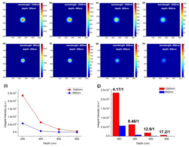
Figure 4 shows the intensity distribution of focal spots of 1040 nm and 800 nm laser beams in biological tissue at some representative depths, according to Monte Carlo simulation. Near the surface of tissue, as shown by Fig. 4(a) and 4(e), the size of the focal spot of the 1040 nm light beam is larger than that of 800 nm light beam, which was due to the diffraction effect. With the increase of the focal depth, as shown in Fig. 4(a)-4(d) and 4(e)-4(h), the intensities of the focal spots of both two laser beams decreased, since light scattering existed in the tissue. However, the 1040 nm laser beam has a better focusing than 800 nm laser beam, as light with longer wavelength has less scattering effect. As shown in Fig. 4(i), the calculated integral intensity of the focal spot of 1040 nm laser beam is always higher than that of 800 nm laser beam, from depth of 200 μm to 800 μm. In addition, the focal spot intensity ratio of 1040 nm to 800 nm laser beam increases with increasing imaging depth, from a value of 4.17 at 200 μm to a larger value of 17.2 at 800 μm. The simulation results illustrate that 1040 nm laser beam has better penetration and focusing capability than 800 nm laser beam in biological tissue, and 1040 nm fs laser is more suitable than 800 nm fs laser as two-photon excitation source for deep-tissue in vivo bioimaging.
Fig. 4.
Simulation of the light intensity distribution of 1040 nm and 800 nm laser beams in biological tissue at various vertical depths. (a-d) The simulated focal spots of 1040 nm laser beam at depths of 200 μm, 400 μm, 600 μm and 800 μm. (e-h) The simulated focal spots of 800 nm laser beam at depths of 200 μm, 400 μm, 600 μm and 800 μm. (i) The simulated light intensity of focal spots of 1040 nm and 800 nm laser beams at depths of 200 μm, 400 μm, 600 μm and 800 μm. (j) The focal spot intensity ratio of 1040 nm to 800 nm laser beam at depths of 200 μm, 400 μm, 600 μm and 800 μm.
3.4 Biodistribution and clearance of BT nanodots in mice
To verify the distribution and clearance of BT nanodots in tissue, the mice were intravenously injected with 200 μL PBS (1 × ) dispersion containing BT nanodots via their tail veins, while some mice were injected with only 200 μL PBS (1 × ) solution as the control group. Major organs including heart, liver, spleen, lungs and kidney were resected 3, 6, 12, 24 and 72 hours after injection and then imaged on the Maestro optical imaging system (CRI, Inc. Woburn, MA).
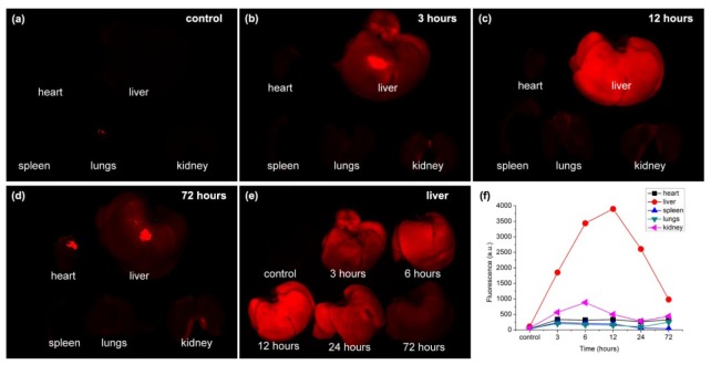
The fluorescence images of the major organs of the mice 3, 12, and 72 hours post the injection of BT nanodots, as well as those of the control group, were shown in Fig. 5(a)-5(d). Fluorescence signals could only be clearly detected in the organs of the organs of mice with the injection of BT nanodots, and almost no signals could be detected in the control group, indicating that the fluorescence should be from BT nanodots in the organs. Liver had brighter fluorescence than other organs, indicating BT nanodots mainly accumulated in the liver of mice, which might due to its detoxification function. As shown in Fig. 5(e), the fluorescence signal in liver reached maxima about 12 hours post sample-injection, and gradually decreased since then. The fluorescence signal in liver was weak 72 hours after injection, indicating BT nanodots could be cleared by liver, via the metabolic function of mice. The fluorescence intensities of different organs at different time points post sample-injection were also summarized in Fig. 5(f).
Fig. 5.
Biodistribution and clearance of BT nanodots in mice. (a)-(d) Fluorescence images of different organs of the control group (a), as well as the mice 3 h (b), 12 h (c), and 72 h (d) post injection of BT nanodots. (e) Fluorescence images of liver of the control group, as well as the mice 3 h, 6h, 12 h, 24 h, and 72 h post injection of BT nanodots. (f) Fluorescence intensities of different organs of the control group, as well as the mice 3 h, 6h, 12 h, 24 h, and 72 h post injection of BT nanodots.
In addition, the behavior of mice with and without the injection of BT nanodots was also studied. 60 days after the treatment, no apparent pathological differences in shape, weight, eating, drinking, exploratory behavior or activity were observed between the two groups. These results indicated that BT nanodots had very little toxicity toward mice, which facilitated their applications in bioimaging.
3.5 BT nanodots for 2PL in vivo microscopic imaging of ear blood vessels of mice
BT nanodots were used for in vivo 2PLimaging of mice ear, with the excitation of 1040 nm fs laser. Since samples were intravenously into mice, the blood vessels of mice were full of BT nanodots due to blood circulation. Figure 6(a)-6(g) show some representative 2PL images of ear blood vessels of a mouse, at various vertical depths. Due to the bright 2PL signals from BT nanodots, as well as low autofluorescence of tissue under 1040 nm fs excitation, the structure of blood vessels at all depths of the mouse ear could be visualized clearly and the signal to noise ratio of all the images was high. The 3D reconstructed 2PL image of BT nanodots in the mouse ear was shown in Fig. 6(h), from which the vascular architecture in the mouse ear was revealed clearly.
Fig. 6.
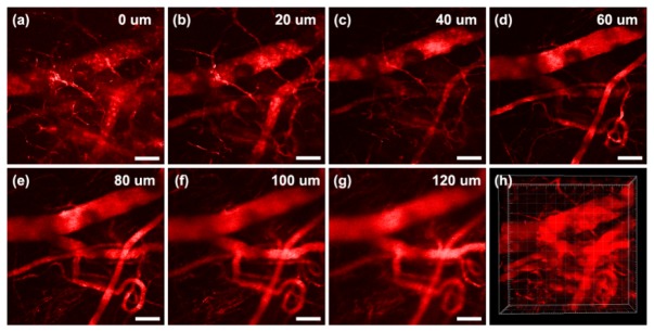
Intravital 2PL imaging of BT nanodots stained ear blood vessels in the mouse, at various vertical depths: (a) 0 μm, (b) 20 μm, (c) 40 μm, (d) 60 μm, (e) 80 μm, (f) 100 μm, (g) 120 μm. (h) 3D reconstructed 2PL images. Scale bar: 100 μm.
3.6 BT nanodots for in vivo 2PL microscopic imaging of brain blood vessels of mice
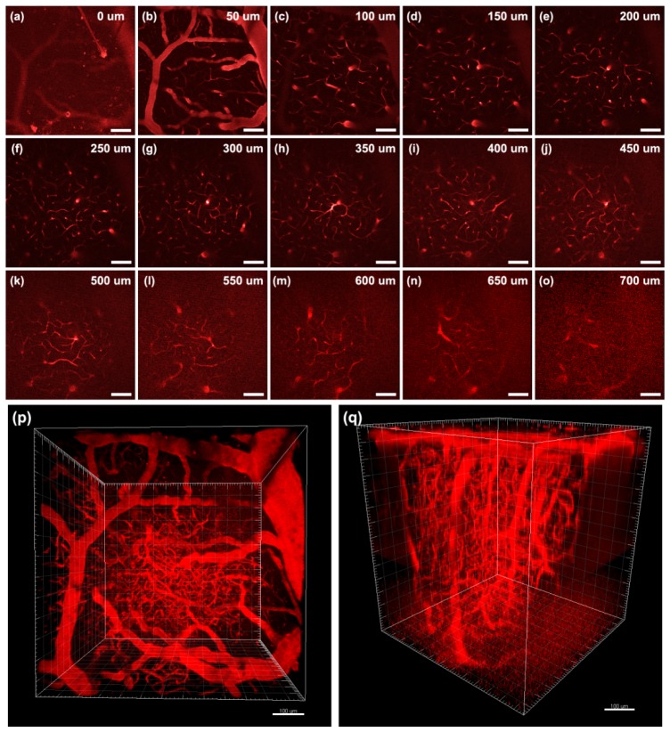
We further performed in vivo brain vasculature imaging of mice with BT nanodots intravenously injected, under the excitation of 1040 nm fs laser, and the images was shown in Fig. 7.
Fig. 7.
Intravital 2PL imaging of BT nanodots stained brain blood vessels in the mouse at various vertical depths: (a) 0 μm, (b) 50 μm, (c) 100 μm, (d) 150 μm, (e) 200 μm, (f) 250 μm, (g) 300 μm, (h) 350 μm, (i) 400 μm, (j) 450 μm, (k) 500 μm, (l) 550 μm, (m) 600 μm, (n) 650 μm, (o) 700 μm.(p, q) 3D reconstructed 2PL images with different visual angles. Scale bar: 100 μm.
Figure 7(a)-7(o) show some representative 2PL images of brain blood vessels of a mouse, at various vertical depths (below the skull). At the surface of brain, the 2PL image contrast was pretty good, and some tiny blood vessels could be visualized clearly, as shown in Fig. 7(b) and 7(c). With increasing imaging depth, the 2PL signal decreased due to the absorption and scattering of 1040 nm fs beam in the tissue. However, a good signal to noise ratio (SNR) was still kept, as shown in Fig. 7(h) and 7(i). The capillaries deep in the pia matter could also be visualized with good contrast. Further increasing image depth would make 2PL signal too weak to be detected, and we gradually increased the power of 1040 nm fs laser as imaging depth got larger. In this case, the 2PL signals from BT nanodots were still bright, but the SNR of image deteriorated gradually as imaging depth increased, as shown in Fig. 7(k)-7(o). The largest 2PL imaging depth could reach 700 μm, and in this depth, the structures of blood vessels were already difficult to be distinguished, as shown in Fig. 7(o). The 3D reconstructed 2PL images of BT nanodots in the mouse brain were shown in Fig. 7(p) and 7(q), with different visual angles. The major blood vessels, as well as small capillaries could be visualized clearly, showing the complicated vasculature in the mouse brain, within a 700 μm depth range. Herein, the deep-tissue 2PL imaging effect was attributed to two factors: the first is that BT nanodots have a very high 2PA cross-section at 1040 nm, and the second is 1040 nm fs laser could penetrate deep and focus well in biological tissues.
4. Conclusions
In summary, a type of red emissive AIE luminogens BT was synthesized and characterized. BT molecules were encapsulated with amphiphilic polymers to form nanodots, and the BT nanodots have large Stokes shift. BT nanodots also have a high 2PL efficiency, with the 2PA cross-section of 2.9 × 10⁶ GM at 1040 nm. In addition, 1040 nm laser beam was found to have a better penetration and focusing capability than 800 nm laser beam in biological tissues, according to the Monte Carlo simulation. The biodistribution and toxicity of BT nanodots were studied, and they were found to have biocompatibility. Combing the above two advantages, 2PL in vivo imaging of mouse ear and brain were conducted by using BT nanodots as the contrast agents, under 1040 nm fs excitation. The 3D architecture of blood vessels was vividly reconstructed and the imaging depth could reach 700 μm in the mouse brain. The red emissive AIE nanodots with high 2PA efficiency at 1040 nm would be useful for deep-tissue functional bioimaging in the future.
Acknowledgment
This work was supported by National Basic Research Program of China (973 Program; 2013CB834704 and 2011CB503700), the National Natural Science Foundation of China (61275190 and 91233208), and the Program of Zhejiang Leading Team of Science and Technology Innovation (2010R50007).
References and links
- 1.Yang Y., Zhao Q., Feng W., Li F., “Luminescent chemodosimeters for bioimaging,” Chem. Rev. 113(1), 192–270 (2013). 10.1021/cr2004103 [DOI] [PubMed] [Google Scholar]
- 2.Brenner D. J., Hall E. J., “Computed tomography - an increasing source of radiation exposure,” N. Engl. J. Med. 357(22), 2277–2284 (2007). 10.1056/NEJMra072149 [DOI] [PubMed] [Google Scholar]
- 3.Ophir J., Alam S. K., Garra B., Kallel F., Konofagou E., Krouskop T., Varghese T., “Elastography: ultrasonic estimation and imaging of the elastic properties of tissues,” Proc. Inst. Mech. Eng. H 213(3 H3), 203–233 (1999). 10.1243/0954411991534933 [DOI] [PubMed] [Google Scholar]
- 4.Ogawa S., Lee T. M., Kay A. R., Tank D. W., “Brain magnetic resonance imaging with contrast dependent on blood oxygenation,” Proc. Natl. Acad. Sci. U.S.A. 87(24), 9868–9872 (1990). 10.1073/pnas.87.24.9868 [DOI] [PMC free article] [PubMed] [Google Scholar]
- 5.Medintz I. L., Uyeda H. T., Goldman E. R., Mattoussi H., “Quantum dot bioconjugates for imaging, labelling and sensing,” Nat. Mater. 4(6), 435–446 (2005). 10.1038/nmat1390 [DOI] [PubMed] [Google Scholar]
- 6.Kobat D., Horton N. G., Xu C., “In vivo two-photon microscopy to 1.6-mm depth in mouse cortex,” J. Biomed. Opt. 16(10), 106014 (2011). 10.1117/1.3646209 [DOI] [PubMed] [Google Scholar]
- 7.Helmchen F., Denk W., “Deep tissue two-photon microscopy,” Nat. Methods 2(12), 932–940 (2005). 10.1038/nmeth818 [DOI] [PubMed] [Google Scholar]
- 8.Albota M., Beljonne D., Brédas J. L., Ehrlich J. E., Fu J. Y., Heikal A. A., Hess S. E., Kogej T., Levin M. D., Marder S. R., McCord-Maughon D., Perry J. W., Röckel H., Rumi M., Subramaniam G., Webb W. W., Wu X. L., Xu C., “Design of organic molecules with large two-photon absorption cross sections,” Science 281(5383), 1653–1656 (1998). 10.1126/science.281.5383.1653 [DOI] [PubMed] [Google Scholar]
- 9.Miller M. J., Wei S. H., Parker I., Cahalan M. D., “Two-photon imaging of lymphocyte motility and antigen response in intact lymph node,” Science 296(5574), 1869–1873 (2002). 10.1126/science.1070051 [DOI] [PubMed] [Google Scholar]
- 10.Drobizhev M., Makarov N. S., Tillo S. E., Hughes T. E., Rebane A., “Two-photon absorption properties of fluorescent proteins,” Nat. Methods 8(5), 393–399 (2011). 10.1038/nmeth.1596 [DOI] [PMC free article] [PubMed] [Google Scholar]
- 11.Larson D. R., Zipfel W. R., Williams R. M., Clark S. W., Bruchez M. P., Wise F. W., Webb W. W., “Water-soluble quantum dots for multiphoton fluorescence imaging in vivo,” Science 300(5624), 1434–1436 (2003). 10.1126/science.1083780 [DOI] [PubMed] [Google Scholar]
- 12.Wang H., Huff T. B., Zweifel D. A., He W., Low P. S., Wei A., Cheng J. X., “In vitro and in vivo two-photon luminescence imaging of single gold nanorods,” Proc. Natl. Acad. Sci. U.S.A. 102(44), 15752–15756 (2005). 10.1073/pnas.0504892102 [DOI] [PMC free article] [PubMed] [Google Scholar]
- 13.Durr N. J., Larson T., Smith D. K., Korgel B. A., Sokolov K., Ben-Yakar A., “Two-photon luminescence imaging of cancer cells using molecularly targeted gold nanorods,” Nano Lett. 7(4), 941–945 (2007). 10.1021/nl062962v [DOI] [PMC free article] [PubMed] [Google Scholar]
- 14.Resch-Genger U., Grabolle M., Cavaliere-Jaricot S., Nitschke R., Nann T., “Quantum dots versus organic dyes as fluorescent labels,” Nat. Methods 5(9), 763–775 (2008). 10.1038/nmeth.1248 [DOI] [PubMed] [Google Scholar]
- 15.Betzig E., Patterson G. H., Sougrat R., Lindwasser O. W., Olenych S., Bonifacino J. S., Davidson M. W., Lippincott-Schwartz J., Hess H. F., “Imaging intracellular fluorescent proteins at nanometer resolution,” Science 313(5793), 1642–1645 (2006). 10.1126/science.1127344 [DOI] [PubMed] [Google Scholar]
- 16.Ullah R., Dutta J., “Photocatalytic degradation of organic dyes with manganese-doped ZnO nanoparticles,” J. Hazard. Mater. 156(1-3), 194–200 (2008). 10.1016/j.jhazmat.2007.12.033 [DOI] [PubMed] [Google Scholar]
- 17.Shimizu K. T., Neuhauser R. G., Leatherdale C. A., Empedocles S. A., Woo W. K., Bawendi M. G., “Blinking statistics in single semiconductor nanocrystal quantum dots,” Phys. Rev. B 63(20), 205316 (2001). 10.1103/PhysRevB.63.205316 [DOI] [Google Scholar]
- 18.Link S., El-Sayed M. A., “Spectroscopic determination of the melting energy of a gold nanorod,” J. Chem. Phys. 114(5), 2362–2368 (2001). 10.1063/1.1336140 [DOI] [Google Scholar]
- 19.Hong Y., Lam J. W. Y., Tang B. Z., “Aggregation-induced emission,” Chem. Soc. Rev. 40(11), 5361–5388 (2011). 10.1039/c1cs15113d [DOI] [PubMed] [Google Scholar]
- 20.Luo J., Xie Z., Lam J. W. Y., Cheng L., Chen H., Qiu C., Kwok H. S., Zhan X., Liu Y., Zhu D., Tang B. Z., “Aggregation-induced emission of 1-methyl-1,2,3,4,5-pentaphenylsilole,” Chem. Commun. (Camb.) 1740(18), 1740–1741 (2001). 10.1039/b105159h [DOI] [PubMed] [Google Scholar]
- 21.Li K., Liu B., “Polymer-encapsulated organic nanoparticles for fluorescence and photoacoustic imaging,” Chem. Soc. Rev. 43(18), 6570–6597 (2014). 10.1039/C4CS00014E [DOI] [PubMed] [Google Scholar]
- 22.Zhang X., Zhang X., Tao L., Chi Z., Xu J., Wei Y., “Aggregation induced emission-based fluorescent nanoparticles: fabrication methodologies and biomedical applications,” J. Mater. Chem. B Mater. Biol. Med. 2(28), 4398–4414 (2014). 10.1039/c4tb00291a [DOI] [PubMed] [Google Scholar]
- 23.Wang D., Qian J., He S., Park J. S., Lee K. S., Han S., Mu Y., “Aggregation-enhanced fluorescence in PEGylated phospholipid nanomicelles for in vivo imaging,” Biomaterials 32(25), 5880–5888 (2011). 10.1016/j.biomaterials.2011.04.080 [DOI] [PubMed] [Google Scholar]
- 24.Wang D., Qian J., Qin W., Qin A., Tang B. Z., He S., “Biocompatible and photostable AIE dots with red emission for in vivo two-photon bioimaging,” Sci. Rep. 4, 4279 (2014). [DOI] [PMC free article] [PubMed] [Google Scholar]
- 25.Cai F., Yu J., He S., “Vectorial electric field Monte Caro simulations for focused laser beams (800 nm-2220 nm) in a biological sample,” Prog. Electromagnetics Res. 142, 667–681 (2013). 10.2528/PIER13080705 [DOI] [Google Scholar]
- 26.Gomez-Duran C. F. A., Hu R., Feng G., Li T., Bu F., Arseneault M., Liu B., Peña-Cabrera E., Tang B. Z., “Effect of AIE substituents on the fluorescence of tetraphenylethene-containing BODIPY derivatives,” ACS Appl. Mater. Interfaces 7(28), 15168–15176 (2015). 10.1021/acsami.5b05033 [DOI] [PubMed] [Google Scholar]
- 27.Liu P., Li S., Jin Y., Qian L., Gao N., Yao S. Q., Huang F., Xu Q. H., Cao Y., “Red-Emitting DPSB-Based Conjugated Polymer Nanoparticles with High Two-Photon Brightness for Cell Membrane Imaging,” ACS Appl. Mater. Interfaces 7(12), 6754–6763 (2015). 10.1021/acsami.5b00223 [DOI] [PubMed] [Google Scholar]
- 28.Geng J., Goh C. C., Tomczak N., Liu J., Liu R., Ma L., Ng L. G., Gurzadyan G. G., Liu B., “Micelle/Silica Co-protected Conjugated Polymer Nanoparticles for Two-Photon Excited Brain Vascular Imaging,” Chem. Mater. 26(5), 1874–1880 (2014). 10.1021/cm4040374 [DOI] [Google Scholar]
- 29.Oulianov D. A., Tomov I. V., Dvornikov A. S., Rentzepis P. M., “Observations on the measurement of two-photon absorption cross-section,” Opt. Commun. 191(3–6), 235–243 (2001). 10.1016/S0030-4018(01)01121-X [DOI] [Google Scholar]
- 30.Makarov N. S., Drobizhev M., Rebane A., “Two-photon absorption standards in the 550-1600 nm excitation wavelength range,” Opt. Express 16(6), 4029–4047 (2008). 10.1364/OE.16.004029 [DOI] [PubMed] [Google Scholar]
- 31.Horton N. G., Wang K., Kobat D., Clark C. G., Wise F. W., Schaffer C. B., Xu C., “In vivo three-photon microscopy of subcortical structures within an intact mouse brain,” Nat. Photonics 7(3), 205–209 (2013). 10.1038/nphoton.2012.336 [DOI] [PMC free article] [PubMed] [Google Scholar]
- 32.Ding H., Lu J. Q., Wooden W. A., Kragel P. J., Hu X. H., “Refractive indices of human skin tissues at eight wavelengths and estimated dispersion relations between 300 and 1600 nm,” Phys. Med. Biol. 51(6), 1479–1489 (2006). 10.1088/0031-9155/51/6/008 [DOI] [PubMed] [Google Scholar]
- 33.Yaroslavsky A. N., Schulze P. C., Yaroslavsky I. V., Schober R., Ulrich F., Schwarzmaier H. J., “Optical properties of selected native and coagulated human brain tissues in vitro in the visible and near infrared spectral range,” Phys. Med. Biol. 47(12), 2059–2073 (2002). 10.1088/0031-9155/47/12/305 [DOI] [PubMed] [Google Scholar]
- 34.Hu R., Gómez-Durán C. F. A., Lam J. W. Y., Belmonte-Vázquez J. L., Deng C., Chen S., Ye R., Peña-Cabrera E., Zhong Y., Wong K. S., Tang B. Z., “Synthesis, solvatochromism, aggregation-induced emission and cell imaging of tetraphenylethene-containing BODIPY derivatives with large Stokes shifts,” Chem. Commun. (Camb.) 48(81), 10099–10101 (2012). 10.1039/c2cc35188a [DOI] [PubMed] [Google Scholar]
- 35.Loudet A., Burgess K., “BODIPY dyes and their derivatives: Syntheses and spectroscopic properties,” Chem. Rev. 107(11), 4891–4932 (2007). 10.1021/cr078381n [DOI] [PubMed] [Google Scholar]
- 36.Hong Y., Lam J. W. Y., Tang B. Z., “Aggregation-induced emission: phenomenon, mechanism and applications,” Chem. Commun. (Camb.) 29, 4332–4353 (2009). 10.1039/b904665h [DOI] [PubMed] [Google Scholar]
- 37.Hu R., Lager E., Aguilar-Aguilar A., Liu J., Lam J. W. Y., Sung H. H. Y., Williams I. D., Zhong Y., Wong K. S., Pena-Cabrera E., Tang B. Z., “Twisted intramolecular charge transfer and aggregation-induced emission of BODIPY derivatives,” J. Phys. Chem. C 113(36), 15845–15853 (2009). 10.1021/jp902962h [DOI] [Google Scholar]
- 38.Ding D., Goh C. C., Feng G., Zhao Z., Liu J., Liu R., Tomczak N., Geng J., Tang B. Z., Ng L. G., Liu B., “Ultrabright organic dots with aggregation-induced emission characteristics for real-time two-photon intravital vasculature imaging,” Adv. Mater. 25(42), 6083–6088 (2013). 10.1002/adma.201301938 [DOI] [PubMed] [Google Scholar]
- 39.Yang Y., An F., Liu Z., Zhang X., Zhou M., Li W., Hao X., Lee C. S., Zhang X., “Ultrabright and ultrastable near-infrared dye nanoparticles for in vitro and in vivo bioimaging,” Biomaterials 33(31), 7803–7809 (2012). 10.1016/j.biomaterials.2012.07.006 [DOI] [PubMed] [Google Scholar]
- 40.Qin W., Ding D., Liu J., Yuan W. Z., Hu Y., Liu B., Tang B. Z., “Biocompatible Nanoparticles with Aggregation-Induced Emission Characteristics as Far-Red/Near-Infrared Fluorescent Bioprobes for In Vitro and In Vivo Imaging Applications,” Adv. Funct. Mater. 22(4), 771–779 (2012). 10.1002/adfm.201102191 [DOI] [Google Scholar]
- 41.Williams A. T. R., Winfield S. A., Miller J. N., “Relative fluorescence quantum yields using a computer controlled luminescence spectrometer,” Analyst (Lond.) 108(1290), 1067–1071 (1983). 10.1039/an9830801067 [DOI] [Google Scholar]


