Abstract
Purpose:
Significant dosimetric benefits had been previously demonstrated in highly noncoplanar treatment plans. In this study, the authors developed and verified an individualized collision model for the purpose of delivering highly noncoplanar radiotherapy and tested the feasibility of total delivery automation with Varian TrueBeam developer mode.
Methods:
A hand-held 3D scanner was used to capture the surfaces of an anthropomorphic phantom and a human subject, which were positioned with a computer-aided design model of a TrueBeam machine to create a detailed virtual geometrical collision model. The collision model included gantry, collimator, and couch motion degrees of freedom. The accuracy of the 3D scanner was validated by scanning a rigid cubical phantom with known dimensions. The collision model was then validated by generating 300 linear accelerator orientations corresponding to 300 gantry-to-couch and gantry-to-phantom distances, and comparing the corresponding distance measurements to their corresponding models. The linear accelerator orientations reflected uniformly sampled noncoplanar beam angles to the head, lung, and prostate. The distance discrepancies between measurements on the physical and virtual systems were used to estimate treatment-site-specific safety buffer distances with 0.1%, 0.01%, and 0.001% probability of collision between the gantry and couch or phantom. Plans containing 20 noncoplanar beams to the brain, lung, and prostate optimized via an in-house noncoplanar radiotherapy platform were converted into XML script for automated delivery and the entire delivery was recorded and timed to demonstrate the feasibility of automated delivery.
Results:
The 3D scanner measured the dimension of the 14 cm cubic phantom within 0.5 mm. The maximal absolute discrepancy between machine and model measurements for gantry-to-couch and gantry-to-phantom was 0.95 and 2.97 cm, respectively. The reduced accuracy of gantry-to-phantom measurements was attributed to phantom setup errors due to the slightly deformable and flexible phantom extremities. The estimated site-specific safety buffer distance with 0.001% probability of collision for (gantry-to-couch, gantry-to-phantom) was (1.23 cm, 3.35 cm), (1.01 cm, 3.99 cm), and (2.19 cm, 5.73 cm) for treatment to the head, lung, and prostate, respectively. Automated delivery to all three treatment sites was completed in 15 min and collision free using a digital Linac.
Conclusions:
An individualized collision prediction model for the purpose of noncoplanar beam delivery was developed and verified. With the model, the study has demonstrated the feasibility of predicting deliverable beams for an individual patient and then guiding fully automated noncoplanar treatment delivery. This work motivates development of clinical workflows and quality assurance procedures to allow more extensive use and automation of noncoplanar beam geometries.
Keywords: collision avoidance, radiotherapy delivery automation, noncoplanar radiotherapy
1. INTRODUCTION
Radiation therapy dosimetry can benefit from expanding the beam orientation solution space to include noncoplanar beams. The improvement is particularly facilitated by recent breakthroughs in robust optimization algorithms capable of automatically solving the complex noncoplanar beam orientation/trajectory, and fluence optimization problem, such as static intensity modulated radiation therapy (IMRT)-based approaches including 4π radiotherapy,1 iCycle,2 and rotational trajectory-based volumetric modulated arc therapy (VMAT) methods including TMAT,3,4 Tra-VMAT,5 and DCR-VMAT.6 Significant dosimetric advantages including improved dose conformality and normal organ sparing have been demonstrated for treatments to the brain,5,7 head and neck,8,9 liver,1 lung,10 breast,3 and prostate11,12 employing a large number of noncoplanar static beams or arcs, in comparison to current state-of-the-art coplanar VMAT and IMRT techniques employing manually selected beams.
Clinical adoption of the plans using increasing number of optimally selected noncoplanar beams and arcs requires the development of corresponding quality assurance protocols. Compared to existing plans that employ dominantly coplanar beams, noncoplanar beam plans increase the possibility of collision between the gantry, couch, and patient. Furthermore, to expand the solution space to include noncoplanar beams, nonisocentric treatments with source-to-target distances (STD) beyond 100 cm that require additional couch translations between beams may be needed. A quantitative and automated process needs to be developed to predict and prevent collisions, and to be able to determine the necessary STD for each beam.
Collision prediction models have been previously developed for the purpose of evaluating collision zones for isocentric treatments and avoiding unforeseen collisions that result in replanning and treatment delays. Humm described a computerized collision prediction method,13 where a simplified 3D surface model of the machine was used and combined with experimental measurements of potential collision points. The patient was modeled as an elliptical cylinder fixed to the couch. The method was later adopted and modified to improve visualization,14–17 incorporate patient-specific external contours from the CT,18 and develop an analytical collision model that is computationally inexpensive.19 Hamza-Lup et al. digitized the surface of individual moveable components on external beam therapy machines using 3D scanners and generated an augmented reality environment for virtual collision detection.20 While these methods provided an approximation for collision prediction, they were either not individualized to each patient, or have not been end-to-end tested for the purpose of noncoplanar radiotherapy. Studies in which patient-specific external contours from CT images were utilized, the patient contour not only does not include the entire body, but also could not be extensively verified via measurements due to the impracticality of placing any patient on the couch for an extended period of time.
In this current study, we report a method to generate an individualized collision model, test its accuracy via extensive measurements with a phantom, and then predict safety buffer distances based on measurements for various treatment sites.
2. METHODS
2.A. Model construction
A highly detailed 3D computer-aided design (CAD) model of a digital Linac (Varian TrueBeam, Varian Medical Systems) provided by the manufacturer was employed. To reduce the file size and improve processing time, components such as nuts and bolts that would not be involved in collisions were removed from the CAD model using engineering software autodesk inventor (Autodesk, San Rafael, CA). The CAD model allowed the gantry and couch to be moved according to the International Electrotechnique Commission (IEC) convention.
A hand-held 3D scanner (Artec MH, Palo Alto, CA) was used to capture the surface geometry of a clothed foam anthropomorphic phantom (Zing Display, Rancho Santa Margarita, CA) in standing position. The phantom was selected for three reasons. First, the phantom material was pliant, yielding under pressure and lessening the risk of damaging the machine in case of an inadvertent collision. Second, the phantom could be placed in different poses to facilitate testing of the collision space with various set up positions. Finally, the full body phantom was relatively light for easy maneuvering.
2.B. 3D scanner specifications and accuracy verification
The 3D scanner projected a patterned pulsed LED laser light for distance measurement. The working distance of the scanner was 0.4–1.0 m with 214 × 148 mm2 field of view at the closest distance and 536 × 371 mm2 at the furthest distance. The frame rate was 15 frames/s. To scan a larger or complete 3D object in the hand-held mode, the camera software fused image patches from multiple views after registration. Because of the high frame rate, there was a large overlap between adjacent patches to facilitate the registration. The 3D scanning resolution was 0.5 mm according to the manufacturer.
The accuracy of the 3D camera was tested by performing a 3D scan on a rigid high precision phantom (MIMI, Standard Imaging, Middleton, WI), as shown in Fig. 1(a). The phantom dimension was 14 × 14 × 14 cm3. The size of the scanned phantom was measured using the 3D scanning software artec studio (Artec Group, Palo Alto, CA).
FIG. 1.
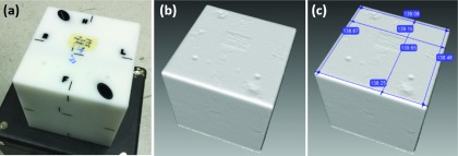
3D scanner verification with the MIMI phantom. (a) MIMI phantom, (b) resultant 3D scan, (c) resultant 3D scan with six measurements in millimeters.
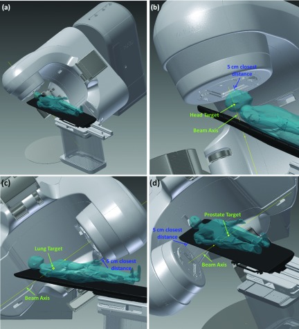
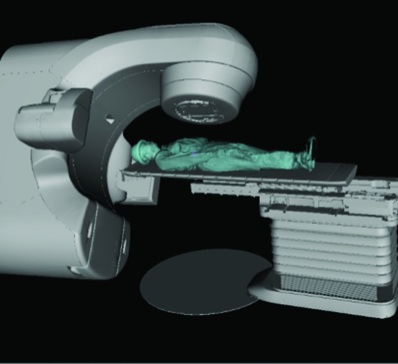
The anthropomorphic phantom surface model was then placed onto the couch within the CAD model to explore the Linac noncoplanar collision space. The same method was used to incorporate a human subject surface in the CAD model.11 The complete CAD model of the TrueBeam system with the phantom on the couch within is shown in Fig. 2(a).
FIG. 2.
(a) Full CAD model within autodesk inventor with phantom on couch. (b) Example 5 cm closest distance measurement for treatment to the head. (c) 5 cm closest distance measurement to lung. (d) Closest distance measurement to prostate.
2.C. Verification between model and physical system with phantom measurements
To explore and verify specifically the noncoplanar beam candidate pool for treatments to the head, lung, and prostate, representative targets of interest of all three sites were added to the phantom surface model. For each treatment site of interest, 100 couch and gantry angle combinations were uniformly sampled from the candidate pool of 1162 beams with 6° of separation between two nearest neighbor beam pairs throughout the entire 4π sr. For each beam angle, the couch position was translated along the beam axis until the closest distance from the gantry to the couch or patient was 5 cm within the CAD model, using
| (1) |
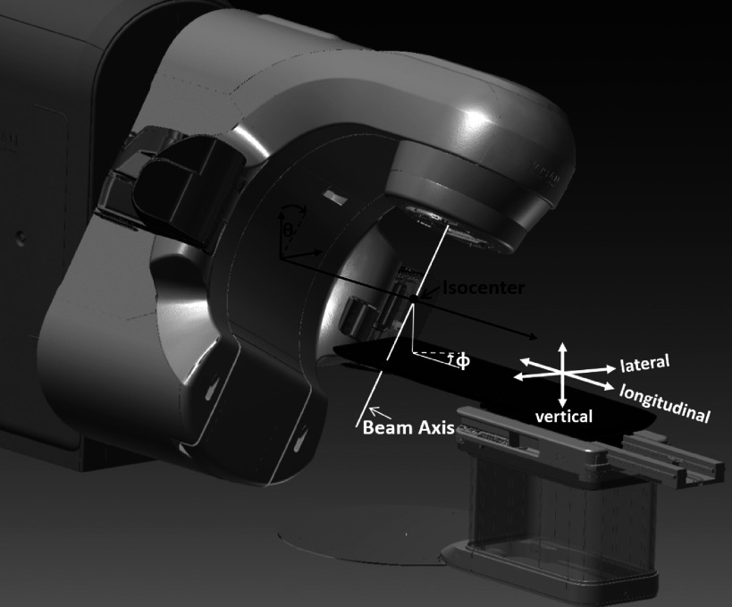
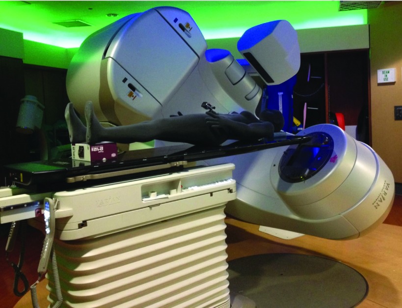
where Δr indicated the displacement of target from the isocenter, θ and ϕ indicated the gantry and couch angles, respectively. The gantry and couch angles followed the IEC convention, as demonstrated in Fig. 3. Lat0, Lng0, and Vrt0 were the couch lateral, longitudinal, and vertical axes positions at which the treatment site of interest was aligned to the machine isocenter. Demonstrations of the closest distance measurements between gantry to patient or couch for treatments to the head, lung, and prostate are shown in Figs. 2(b)–2(d), respectively. The phantom was positioned on the Linac couch based on the CAD model (equivalent to a treatment plan) and all 300 gantry and couch positions (100 positions from each treatment site) were transferred to the Linac for measurement. The measurement setup is shown in Fig. 4. Since the phantom 3D surface model was obtained in standing position, there was a gap between the posterior phantom head and feet surfaces and the couch top. To stabilize the phantom, cushions were placed under the phantom head and feet during measurement. An inside caliper (iGaging, San Clemente, CA) was used to measure the closest distances on the machine setup. The distance discrepancy data points between the CAD and machine measurements were separated into six groups based on the treatment site and measurement location (couch or phantom). The Shapiro–Wilk normality test with an α level of 0.05 was performed on each dataset. For the groups that did not satisfy the normality hypothesis, a double Gaussian fit was performed to find a distribution that best represented the discrepancy data points. The curve fit performance was verified with the Kolmogorov–Smirnov test at an α level of 0.05. The determined distributions were used to estimate safety margins with 0.1%, 0.01%, and 0.001% probability of collision for all six groups based on the treatment site and whether the measurement was gantry-to-couch or gantry-to-patient. The collision probability selected above roughly represents 1 collision/day, 10 days, and 100 days, assuming 30 treatments/day and ∼30 beams per treatment.
FIG. 3.
IEC convention and couch translations.
FIG. 4.
Machine measurement setup.
2.D. Automated 4π delivery
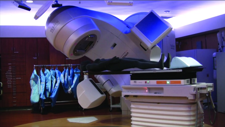
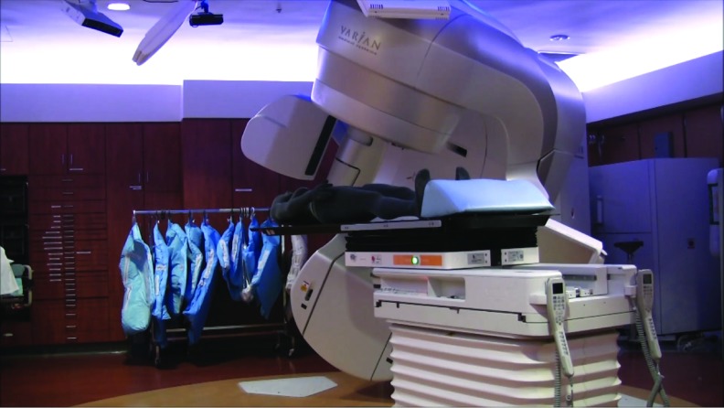
To examine the feasibility and speed of automated treatment delivery, 4π optimized beam angles and the corresponding eclipse optimized MLC sequences of 20 beam brain, lung, and prostate plans were converted into XML script for automatic delivery in the Varian TrueBeam developer mode. The number of beams requiring extended STD to avoid collision within the generated XML delivery brain, lung, and prostate plans were 3, 3, and 6, respectively. The beam angles were sorted in order of couch rotation angle to minimize total couch motion. A GoPro camera was attached at the phantom eye level during the programmed delivery to examine the patient eye view of automated delivery. The whole automated delivery was recorded and timed.
2.E. Exploration of collision-free beam angle solution space with human subject model
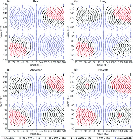
With the developed model, exhaustive search was performed to examine the available beam angle solution space for treatments to the head, lung, abdomen, and prostate. The exhaustive search was performed with a 3D scan of a healthy volunteer placed on the modeled couch. The model was made into an interactive X3D format where the couch and gantry could be moved according to machine specific locations via matlab scripts. The collision status and the particular combination of elements (couch top, couch pedestal, gantry, or imagers) resulting in collision can also be obtained from the model for any Linac orientation. For each treatment site, couch shifts were performed within the model to align the desired treatment target location to the isocenter. For each beam angle within the 4π candidate pool of 1162 beam angles, the minimum STD that was deliverable without collision was automatically calculated by incrementally moving the couch translational axes positions from isocentric setup position via matlab control to extend or shorten the STD based on the collision status of each step until the minimum collision-free STD was found. Using the minimum distance information, the beam angles were sorted into six categories: deliverable with conventional isocentric setup (STD = 100 cm), deliverable only with extended STD between 100 and 110 cm (100 < STD ⩽ 110), 110 and 120 cm (110 < STD ⩽ 120), 120 and 130 cm (120 < STD ⩽ 130), more than 130 cm (STD > 130 cm), and undeliverable. The undeliverable beams resulted in either gantry-to-couch or gantry-to-patient collision, or required one or more couch translational axes to exceed the allowed mechanical range.
3. RESULTS
3.A. 3D scanner accuracy verification
The resultant scan and measurements are shown in Figs. 1(b) and 1(c). The average of six measurements was 138.88 ± 0.52 mm or 0.8% relative error.
3.B. Verification between model and physical system with phantom measurements
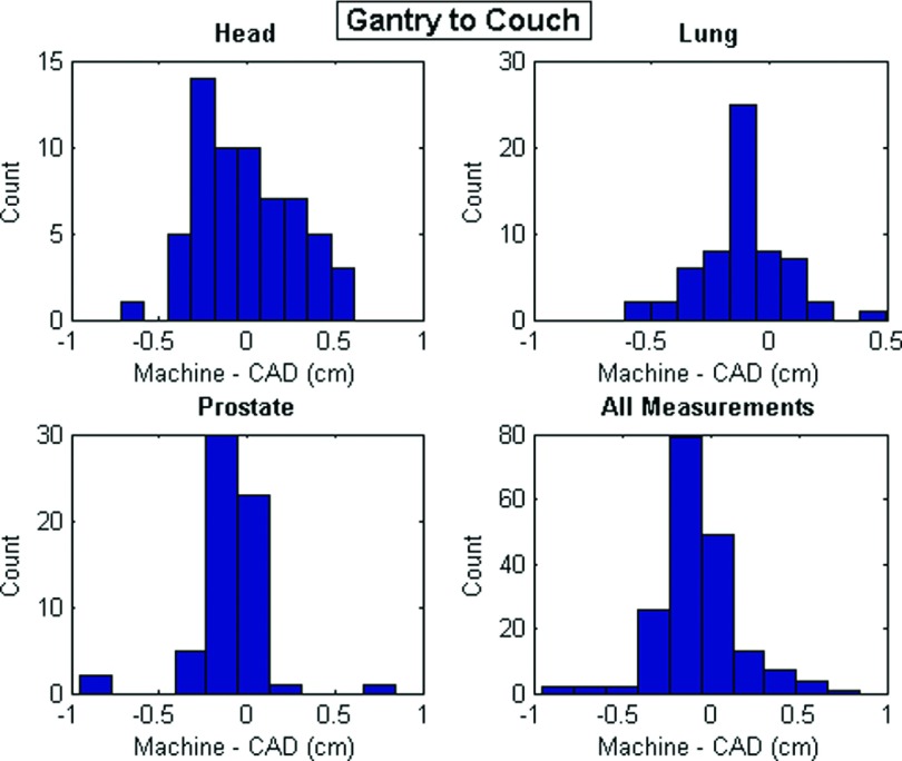
The mean and maximum absolute values of measurement discrepancies and the summary statistics of all discrepancies as either single or double Gaussian distributions for all groups are shown in Table I. For the double Gaussian distributions, the mixture weight of the first listed distribution (μ1, σ1) is represented in the column labeled w1. The discrepancy histograms of all gantry-to-couch and gantry-to-phantom measurements are shown in Figs. 5 and 6, respectively. The discrepancy values between the gantry and couch were all less than 1 cm. The discrepancies between the measurement and the CAD model for gantry-to-phantom distances were greater with a maximum deviation measurement of 2.97 cm, which resulted from a phantom to gantry distance for prostate treatment.
TABLE I.
Gantry-to-couch and gantry-to-phantom measurement statistics.
| |Machine-CAD| | Machine-CAD | ||||||||
|---|---|---|---|---|---|---|---|---|---|
| No. of measurements | Mean | Max | Normality | w1 | μ1 | σ1 | μ2 | σ2 | |
| Couch to gantry | |||||||||
| Head | 62 | 0.24 | 0.72 | Yes | −0.004 | 0.29 | |||
| Lung | 61 | 0.17 | 0.61 | No | 0.66 | −0.11 | 0.05 | −0.12 | 0.001 |
| Prostate | 62 | 0.15 | 0.95 | No | 0.86 | −0.08 | 0.01 | −0.19 | 0.27 |
| All | 185 | 0.18 | 0.95 | No | 0.59 | −0.11 | 0.01 | −0.02 | 0.12 |
| Phantom to gantry | |||||||||
| Head | 38 | 0.88 | 2.95 | Yes | 0.68 | 0.94 | |||
| Lung | 39 | 0.80 | 2.19 | Yes | 0.23 | 0.99 | |||
| Prostate | 38 | 1.45 | 2.97 | No | 0.86 | 1.48 | 0.65 | −0.32 | 2.09 |
| All | 115 | 1.04 | 2.97 | Yes | 0.71 | 1.10 | |||
FIG. 5.
Distance discrepancy histograms for gantry-to-couch measurements.
FIG. 6.
Distance discrepancy histograms for gantry-to-phantom measurements.
Estimates of treatment-site-specific and overall safety buffer distances with 0.01%, 0.001%, and 0.0001% probability of collision between the gantry-to-couch or phantom based on the fitted Gaussian distributions are also shown in Table II. The maximum discrepancy and safety margin estimates were largest for treatments to the prostate for both gantry-to-couch and gantry-to-phantom measurements. The larger discrepancy values of the prostate measurements resulted from the larger number of closest distance measurements from the gantry to the phantom extremities such as the legs and hands, whose positions cannot be exactly reproduced. The non-normality of the gantry-to-phantom distributions were most likely resulted from the differing setup deviation for different parts of the phantom, as the setup reproducibility for the phantom torso and head were better than its extremities. It is apparent from Fig. 5 that the distribution of gantry-to-couch prostate measurements is non-normal due to outliers. The three outliers resulted from measurements close to the couch corners, which we concluded was due to measurement errors in determining the exact set of two points that resulted in the closest distance between two curved surfaces for each measurement.
TABLE II.
Treatment-site-specific safety buffer distance estimations with different collision probabilities.
| Couch-to-gantry | Phantom to gantry | |||||
|---|---|---|---|---|---|---|
| Safety buffer distances (cm) | ||||||
| Head | 0.89 | 1.07 | 1.23 | 2.24 | 2.83 | 3.35 |
| Collision probabilities (%) | 0.1 | 0.01 | 0.001 | 0.1 | 0.01 | 0.001 |
| Lung | 0.75 | 0.89 | 1.01 | 2.83 | 3.45 | 3.99 |
| Prostate | 1.48 | 1.87 | 2.19 | 3.87 | 4.93 | 5.73 |
| All | 0.98 | 1.21 | 1.41 | 2.68 | 3.37 | 3.97 |
3.C. Automated 4π delivery
The automated delivery times of the 20 beam 4π treatments to the brain, lung, and prostate were 10, 12, and 15 min. The number of MLC segments generated by eclipse for the delivered brain, lung, and prostate cases were 582, 205, and 265. The patient point-of-view video along with a synchronized room-view video for the brain case, and the room-view videos for the lung and prostate cases are represented in Figs. 7–9 (Multimedia view). The XML files of all three deliveries are available as supplementary material25 to this paper. All videos were sped up eight times.
FIG. 7.
FIG. 8.
FIG. 9.
3.D. Exploration of collision-free beam angle solution space with human subject model
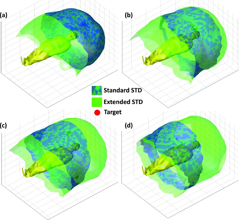
The distribution of beam angles in the standard STD, extended STD, and undeliverable categories for each treatment site based on a healthy volunteer are shown in Table III. The scanning time was approximately 15 min while the subject was in the standing position. The model of the healthy volunteer on the couch is shown in Fig. 10. As expected, treatment to the head allowed for a larger number of total angles and standard STD angles compared with the lung, abdomen, and prostate cases. The total number of deliverable beams reduced from 963 for treatment to the head to 842 for treatment to the prostate. In addition, only 55% of the beams that were deliverable in the standard STD setup for the head remained deliverable in the standard STD setup for the prostate treatment. The extended and standard STD beam solution space surfaces for treatment of the head, lung, abdomen, and prostate are demonstrated in Figs. 11(a)–11(d), respectively. While these images show an intuitive rendering of the collision space, it is helpful to express them in Linac coordinates to guide beam orientation selection and navigation. The gantry vs couch angles of treatments to the head, lung, abdomen, and prostate are shown in Figs. 12(a)–12(d) with the standard STD beams shown as blue hollow circles, extended STD beams shown in black, where 100 < STD ⩽ 110, 110 < STD ⩽ 120, 120 < STD ⩽ 130, and STD > 130 categories are specified as squares, triangles, diamonds, and plus signs, respectively, and undeliverable beams shown as red crosses.
TABLE III.
Beam angle distribution in standard STD, extended STD, and undeliverable categories for treatments to the head, lung, abdomen, and prostate.
| Undeliverable beams | Deliverable with standard STD | Deliverable with extended STD | |
|---|---|---|---|
| Head | 199 | 786 | 177 |
| Lung | 207 | 452 | 503 |
| Abdomen | 219 | 471 | 472 |
| Prostate | 320 | 435 | 407 |
FIG. 10.
Exhaustive search model with healthy volunteer model on couch.
FIG. 11.
Treatment-site-specific beam solution space for standard and extended STD setups. (a) Head, (b) left lung, (c) abdomen, (d) prostate.
FIG. 12.
Gantry vs couch angle plots for treatment to the head, lung, abdomen, and prostate. The infeasible, standard STD beams are represented as red crosses and blue hollow circles, respectively. Extended STD beams are shown in black, separated into four categories: 100 < STD ⩽ 110, 110 < STD ⩽ 120, 120 < STD ⩽ 130, and STD > 130, represented as squares, triangles, diamonds, and plus signs.
4. DISCUSSION
With the emergence of digital Linacs, innovative and effective algorithms to automate the beam orientation/trajectory, and fluence map optimization, there has been a renewed interest in noncoplanar radiotherapy. For example, for centrally located and larger lung tumors, late radiation toxicity still remains a major limitation in delivering effective tumor control dose.21 For recurrent head and neck patients, delivering high dose to the tumor while sparing previously treated organs-at-risk is also still extremely challenging.22 With 4π radiotherapy, we have demonstrated for both these clinical scenarios the potential for dose escalation and significant improvements in critical organ sparing, tumor control, and PTV coverage.8,10 Using optimized noncoplanar trajectories in VMAT, Wild et al. showed that the critical organ mean and max doses can be reduced by 19% for nasopharyngeal patients, compared to coplanar VMAT plans.9 Fahimian et al., Liang et al., and Popescu et al. also demonstrated significant V50% volume reduction of up to 49% for accelerated partial breast irradiation (APBI) with optimized couch and gantry dynamic arc rotation trajectories.3,4,23 The significant dosimetry improvement observed in the aforementioned studies should motivate clinical adoption of noncoplanar IMRT and trajectory-based VMAT for wider applications. For example, a prospective clinical trial is undergoing at UCLA to test the safety, efficiency, and patient tolerance for plans using inverse-optimized noncoplanar IMRT beams.
A major difference between highly noncoplanar treatments and conventional coplanar treatments is the need for substantial couch motion. Quality assurance procedures have been previously developed to evaluate the dosimetric and geometric fidelity of treatment techniques involving couch motion.24 The positional accuracy, velocity constancy, and accuracy for dynamic couch motion were evaluated by performing a series of tests within Varian developer mode. The tests demonstrated the programmed couch translation accuracy to be within 0.01 cm, with rotation accuracy of 0.3°. The test provided the realistic performance accuracy boundary of an aspect of the digital Linac for extensive couch movements. However, the geometric modeling and QA needs for collision avoidance for such treatments had not been addressed.
To overcome these challenges, we introduced a patient-specific collision prediction model. The model was based on a vendor provided machine CAD geometry and patient 3D surface created using 3D scanning technology. The accuracy of the model was measured on the Linac.
Based on our measurement, the CAD model of the gantry and couch was accurate within 1 cm including the uncertainties that arose from measuring the minimal distance between two blunt objects. Other sources of error included the slight deformation of the fiberglass gantry cover due to gravity and the magnification effect of couch rotational uncertainties at a distance from the rotational axis. A 0.3° couch rotational error would introduce a 5.2 mm translational error at 1 m away from the rotational axis. In practice, some of the newer clinical systems such as the TrueBeam used in this study already contain robust built-in motion interlocks to prevent collisions between the gantry and couch based on CAD models. However, modifications to the machine surface, including accessories on the gantry and the addition of third party 6 DOF couch top would require new CAD models to predict the collision-free space.
The slightly larger uncertainties in determining the gantry-to-phantom distances were caused by the following reasons. First, there was an intrinsic limitation in the hand-held 3D scanning accuracy. Based on the relative measurement error of the scanner, for a 1.8 m tall phantom, the measurement error would be 1.5 cm for extreme points. The uncertainty could be reduced by using room mounted 3D cameras that would be more stable, along with further camera calibration. Second, the flexible phantom extremities were not immobilized, which is typical in patient treatment. However, the use of a whole body immobilization device may help reduce the uncertainty compared with the phantom used in this study. Despite our best effort in setting up the phantom according to the CAD model, there were residual errors. This uncertainty particularly contributed to the prostate site where the flexible phantom extremities were frequently in close proximity to the gantry. Finally, the phantom surface yielded under pressure, which made measurement of the minimal gap distances more difficult. In practice, all the uncertainties in the phantom study would still contribute to the patient collision modeling, but the risk of collision can be effectively minimized by employing buffer distances.
The discrepancies between model and measurement were used to calculate safety margin distances with 0.1%, 0.01%, and 0.001% probability of collision between the gantry-to-couch or phantom. Applying Gaussian predicted safety buffer distances to all beam orientations could be biased by outliers involving situations such as glancing angles and tends to overestimate the buffer. The error distribution could also depend on individual patients, immobilization device, and treatment sites. We will prospectively acquire more patient data to better understand the statistics in a future study.
By establishing a collision model that includes a patient model, the deliverable beams and the extended STD needed for certain beam orientation and treatment sites could be determined. Therefore, the collision model is an integrated component of the automated planning system utilizing the entire feasible noncoplanar beam space. For pelvis treatments, the isocentric treatment beam solution space significantly decreases the number of useful beams. The ability to use extended STD beams is essential in maintaining the size of the noncoplanar beam solution space and maximizing the dosimetric benefits. Our model provides a quantitative guidance for selecting these beams and choreographing the gantry and couch motion to achieve these positions as demonstrated in the automated plan delivery in the TrueBeam developer mode. Both the collision space modeling and automation are shown essential as the plan complexity increases.
It is also important to point out that in practice, we should not rely only on the 3D modeling to ensure treatment safety. Secondary and possibly tertiary collision prevention mechanisms should be in place to stop the machine when it is within a preset proximity to the patient. On the other hand, the 3D modeling should minimize the chance of triggering the secondary interlock and maintain the clinical flow.
5. CONCLUSION
In this study, an individualized collision prediction model was developed and verified. With help from the model, we have demonstrated the feasibility of fully automated noncoplanar treatment delivery on a digital Linac. This work motivates further developments of clinical workflows and quality assurance procedures to allow more extensive use and automation of noncoplanar beam geometries for improved radiation dose conformality.
ACKNOWLEDGMENTS
This study is supported in part by Varian Medical Systems, NIH Grant No. R21CA161670, and the National Science Foundation graduate research fellowship (No. DGE-1144087).
REFERENCES
- 1.Dong P. et al. , “4π non-coplanar liver SBRT: A novel delivery technique,” Int. J. Radiat. Oncol., Biol., Phys. 85, 1360–1366 (2013). 10.1016/j.ijrobp.2012.09.028 [DOI] [PubMed] [Google Scholar]
- 2.Breedveld S. et al. , “iCycle: Integrated, multicriterial beam angle, and profile optimization for generation of coplanar and noncoplanar IMRT plans,” Med. Phys. 39, 951–963 (2012). 10.1118/1.3676689 [DOI] [PubMed] [Google Scholar]
- 3.Fahimian B. et al. , “Trajectory modulated prone breast irradiation: A LINAC-based technique combining intensity modulated delivery and motion of the couch,” Radiother. Oncol. 109, 475–481 (2013). 10.1016/j.radonc.2013.10.031 [DOI] [PubMed] [Google Scholar]
- 4.Liang J. et al. , “Trajectory modulated arc therapy: A fully dynamic delivery with synchronized couch and gantry motion significantly improves dosimetric indices correlated with poor cosmesis in accelerated partial breast irradiation,” Int. J. Radiat. Oncol., Biol., Phys. 92, 1148–1156 (2015). 10.1016/j.ijrobp.2015.04.034 [DOI] [PubMed] [Google Scholar]
- 5.Yang Y. et al. , “Choreographing couch and collimator in volumetric modulated arc therapy,” Int. J. Radiat. Oncol., Biol., Phys. 80, 1238–1247 (2011). 10.1016/j.ijrobp.2010.10.016 [DOI] [PubMed] [Google Scholar]
- 6.Smyth G. et al. , “Trajectory optimization for dynamic couch rotation during volumetric modulated arc radiotherapy,” Phys. Med. Biol. 58, 8163–8177 (2013). 10.1088/0031-9155/58/22/8163 [DOI] [PubMed] [Google Scholar]
- 7.Nguyen D. et al. , “Feasibility of extreme dose escalation for glioblastoma multiforme using 4π radiotherapy,” Radiat. Oncol. 9, 239 (2014). 10.1186/s13014-014-0239-x [DOI] [PMC free article] [PubMed] [Google Scholar]
- 8.Rwigema J.-C.M. et al. , “4π noncoplanar stereotactic body radiation therapy for head-and-neck cancer: Potential to improve tumor control and late toxicity,” Int. J. Radiat. Oncol., Biol., Phys. 91, 401–409 (2015). 10.1016/j.ijrobp.2014.09.043 [DOI] [PubMed] [Google Scholar]
- 9.Wild E. et al. , “Noncoplanar VMAT for nasopharyngeal tumors: Plan quality versus treatment time,” Med. Phys. 42, 2157–2168 (2015). 10.1118/1.4914863 [DOI] [PubMed] [Google Scholar]
- 10.Dong P. et al. , “4π noncoplanar stereotactic body radiation therapy for centrally located or larger lung tumors,” Int. J. Radiat. Oncol., Biol., Phys. 86, 407–413 (2013). 10.1016/j.ijrobp.2013.02.002 [DOI] [PubMed] [Google Scholar]
- 11.Dong P. et al. , “Feasibility of prostate robotic radiation therapy on conventional C-arm linacs,” Pract. Radiat. Oncol. 4, 254–260 (2014). 10.1016/j.prro.2013.10.009 [DOI] [PubMed] [Google Scholar]
- 12.Rossi L. et al. , “On the beam direction search space in computerized non-coplanar beam angle optimization for IMRT-prostate SBRT,” Phys. Med. Biol. 57, 5441–5458 (2012). 10.1088/0031-9155/57/17/5441 [DOI] [PubMed] [Google Scholar]
- 13.Humm J. L., “Collision avoidance in computer optimized treatment planning,” Med. Phys. 21, 1053–1064 (1994). 10.1118/1.597397 [DOI] [PubMed] [Google Scholar]
- 14.Humm J. L. et al. , “Collision detection and avoidance during treatment planning,” Int. J. Radiat. Oncol., Biol., Phys. 33, 1101–1108 (1995). 10.1016/0360-3016(95)00155-7 [DOI] [PubMed] [Google Scholar]
- 15.Tsiakalos M. F. et al. , “Graphical treatment simulation and automated collision detection for conformal and stereotactic radiotherapy treatment planning,” Med. Phys. 28, 1359–1363 (2001). 10.1118/1.1381552 [DOI] [PubMed] [Google Scholar]
- 16.Chao M. M. et al. , “Image display for collision avoidance of radiation therapy: Treatment planning,” J. Digit. Imaging 14, 186–191 (2001). 10.1007/s10278-001-0104-y [DOI] [PMC free article] [PubMed] [Google Scholar]
- 17.Becker S. J., “Collision indicator charts for gantry-couch position combinations for Varian linacs,” J. Appl. Clin. Med. Phys. 12, 3405–3411 (2011). 10.1120/jacmp.v12i3.3405 [DOI] [PMC free article] [PubMed] [Google Scholar]
- 18.Nioutsikou E., Bedford J. L., and Webb S., “Patient-specific planning for prevention of mechanical collisions during radiotherapy,” Phys. Med. Biol. 48, N313–N321 (2003). 10.1088/0031-9155/48/22/N02 [DOI] [PubMed] [Google Scholar]
- 19.Hua C. et al. , “A practical approach to prevent gantry-couch collision for linac-based radiosurgery,” Med. Phys. 31, 2128–2134 (2004). 10.1118/1.1764391 [DOI] [PubMed] [Google Scholar]
- 20.Hamza-Lup F., Sopin I., and Zeidan O., “Online external beam radiation treatment simulator,” Int. J. Comput. Assist. Radiol. Surg. 3, 275–281 (2008). 10.1007/s11548-008-0232-7 [DOI] [Google Scholar]
- 21.Cannon D. M. et al. , “Dose-limiting toxicity after hypofractionated dose-escalated radiotherapy in non-small-cell lung cancer,” J. Clin. Oncol. 31, 4343–4348 (2013). 10.1200/JCO.2013.51.5353 [DOI] [PMC free article] [PubMed] [Google Scholar]
- 22.Duprez F. et al. , “High-dose reirradiation with intensity-modulated radiotherapy for recurrent head-and-neck cancer: Disease control, survival and toxicity,” Radiother. Oncol. 111, 388–392 (2014). 10.1016/j.radonc.2014.04.018 [DOI] [PubMed] [Google Scholar]
- 23.Popescu C. C. et al. , “Simultaneous couch and gantry dynamic arc rotation (CG-Darc) in the treatment of breast cancer with accelerated partial breast irradiation (APBI): A feasibility study,” J. Appl. Clin. Med. Phys. 14, 4035 (2013). 10.1120/jacmp.v14i1.4035 [DOI] [PMC free article] [PubMed] [Google Scholar]
- 24.Yu V. Y. et al. , “Quality control procedures for dynamic treatment delivery techniques involving couch motion,” Med. Phys. 41, 081712(7pp.) (2014). 10.1118/1.4886757 [DOI] [PubMed] [Google Scholar]
- 25.See supplementary material at http://dx.doi.org/10.1118/1.4932631 E-MPHYA6-42-038511 for the XML files of all three deliveries.
Associated Data
This section collects any data citations, data availability statements, or supplementary materials included in this article.
Data Citations
- See supplementary material at http://dx.doi.org/10.1118/1.4932631 E-MPHYA6-42-038511 for the XML files of all three deliveries.


