

Abstract
Objective: This study aims to explore the mechanical stability of combined plate internal fixation in posterior wall fractures of the acetabulum. Methods: The fracture and internal fixation models were established in this study and they were divided into four kinds of internal fixation models, finite element analysis was performed. The four groups were 2 mini-plates and 1 reconstruction plate fixation (A), Reconstruction plate internal fixation group (B), 2 screws internal fixation group (C) and mini-plates internal fixation group (D). The displacement of each node was measured and evaluated. Results: There was no distortion in the geometric shape of the finite element model. The results of stress showed that it was less in the anterior pelvic ring and distributed uniform in labrum acetabulare; the stress was bigger in the upper and middle of sacroiliac joint and sciatic notch in sitting position. Conclusions: Combined plate internal fixation for posterior wall fractures of acetabular were stable and reliable, it is better than the other three methods.
Keywords: Finite element, posterior wall, acetabular fracture, mini-plate
Introduction
The posterior wall fracture of the acetabulum is the most common type of all acetabular fractures, which account for 20.5% [1]. The diagnosis and treatment of the posterior wall fracture of acetabulum is relatively easy. However, about 1/3 patients were not satisfied with the curative effect of operation [2]. There were many factors affected the curative effect, the main reason was the bad reduction and fixation of fracture block in operation process. Many studies showed that reduction of acetabular fractures was the key for good curative effect [1-3]. In recent years we fixed the posterior wall fracture of acetabulum with mini combined plate internal fixation and got satisfactory effect [3]. In this study we studied the biomechanical stability of this internal fixation with the three-dimensional finite element method, which could provide biomechanical basis for its clinical application.
Materials and methods
Pelvis model establishment
We chose a healthy adult male volunteer and scan his pelvis using 16 multislice spital computed tomography (Siemens, German) and 0.5 mm layer. The volunteer did not move along the longitudinal axis of the pelvis in scan process and the scan images were saved. The image files were imported into special medical modeling software Mimics10.1 (Materialise, Belgium) to reconstruct the digital three-dimensional pelvis. Then the data were imported into finite element analysis software ANSYS12.0-ICEM (ANSYS, USA) and Hypermesh V10.0 (Altair, USA) to mesh them. The model included left and right ilium, sacrum, sacral endplate and cartilage, ilium endplate and cartilage, interpubic disc and so on. They were shown in Figure 1. The main pelvic ligaments were established according to reference [4]; they included sacroiliac ligament, sacrospinous ligament, sacrotuberous ligament, inguinal ligament and so on. The mechanical properties of biological materials were assumed to be continuous, isotropic and homogeneous (Tables 1 and 2) [5] and the thickness of the cortical bone was defined as 1.5 mm [6]. The effectiveness of model geometry was verified and its mechanical properties were verified by Abaqus 6.12 software.
Figure 1.
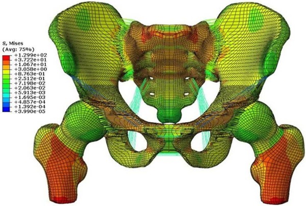
Stress images of finite element model of standing position.
Table 1.
Characteristics of materials used in pelvic three-dimensional finite element model
| Area and material | Young’s modulus (MPa) | Poisson’s ratio u | Thickness (d/mm) |
|---|---|---|---|
| Cortical bone (Sacrum) | 17,000 | 0.30 | 1.50 |
| Cortical bone (ilium) | 17,000 | 0.30 | 1.50 |
| Cancellous bone (Sacrum) | 150 | 0.20 | |
| Cancellous bone (ilium) | 150 | 0.20 | |
| Endplate (ilium) | 500 | 0.25 | 0.36 |
| Cartilage (ilium) | 1,000 | 0.30 | 1.00 |
| Endplate (Sacrum) | 500 | 0.25 | 0.23 |
| Cartilage (Sacrum) | 1,000 | 0.30 | 3.00 |
Table 2.
Modeling parameters of pelvic main ligaments
| Ligament | K (N/mm) | Attachment area (mm2) | Number of springs |
|---|---|---|---|
| Sacroiliac | 5000 | 1391 | 525 |
| Sacrospinous | 1500 | 112 | 12 |
| Sacrotuberous | 1500 | 539 | 56 |
| Iliolumbar | 1000 | 506 | 50 |
| Inguinal* | 250 | 45 | 9* |
| Superior pubic | 500 | 97 | 10 |
| cuate pubic | 500 | 156 | 15 |
Sum of two halves of the ligament.
Establishment of fracture and internal fixation model
The 2/3 posterior wall fracture of acetabulum model was established according to reference [7]. The internal fixation model was established using software. The reconstruction mini-plate, reconstruction plate and 2 screws were drawn using the Hypermesh V10.0 software and they were imported into Abaqus 6.12 software. The plates and screws and bones were restrained by embedding and coupling methods. Four kinds of internal fixation models were established: Combined plates internal fixation group (A), 2 mini-plates and 1 reconstruction plate fixation. The mini-plates were placed in the side of the fracture line, the reconstruction plate was placed in fracture block ends with 3 screws, its middle was placed on mini-plates and the mini-plates were fixed with screws. Reconstruction plate internal fixation group (B), 1 reconstruction plate with 8 screws fixation. 2 screws internal fixation group (C), cortical bone screw with 3.5 mm diameter. Mini-plates internal fixation group (D), 2 mini-plates and 4 screws in each mini-plate [8]. Given the load at the geometric center of model and the load was 600 N.
Evaluation index of models
The each node of fracture line consisted a fracture line path and the displacement of each node were measured, the greater the displacement the more unstable.
Statistic analysis
The data were analyzed using SPSS 17 software. Single factor analysis of variance was used to compare among groups. P<0.05 was considered to be significant.
Results
Model overview
The finite element pelvis models of standing and sitting position established in this study were shown in Figure 2. The distance between grid nodes in acetabular area was optimized for 1 mm and the distance between grid nodes in other area was 3 mm. The grid numbers in finite element pelvis models of standing position were 175586 and total nodes were 236151. Figure 3 showed four kinds of internal fixation models.
Figure 2.
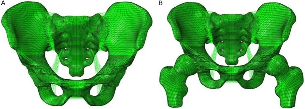
Three-dimensional finite element models of whole pelvis of standing and sitting position. A: Sitting position; B: Standing position.
Figure 3.
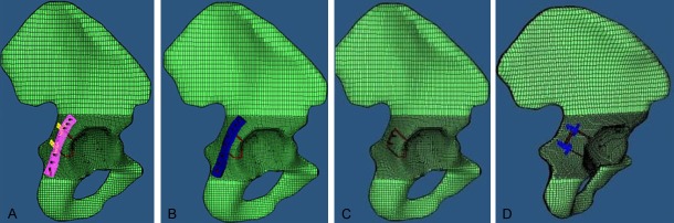
Models’ images. A: 2 mini-plates and 1 reconstruction plate fixation group; B: Reconstruction plate internal fixation group; C: 2 screws internal fixation group; D: Mini-plates internal fixation group.
Validation results of effectiveness
The distance of each measuring point between the finite element model (FEM) and the three-dimensional reconstruction model was shown in Table 3. The data were analyzed by t-test and the results suggested that these two models coincide (P>0.05) and there was no distortion in the geometric shape of the finite element model. The results of stress showed that it was less in the anterior pelvic ring and distributed uniform in labrum acetabulare; the stress was bigger in the upper and middle of sacroiliac joint and sciatic notch in sitting position. The results were in accordance with theoretical cognition and other studies [6]. These proved that the pelvic finite element model established in this study was effective.
Table 3.
Comparison of the distance (d) of each measuring point between the finite element model (FEM) and the three-dimensional reconstruction model (RM). (mm) P=0.949
| 1 | 2 | 3 | 4 | 5 | 6 | 7 | 8 | 9 | |
|---|---|---|---|---|---|---|---|---|---|
| RM (d1) | 158.1 | 201.8 | 100.2 | 109.7 | 121.6 | 54.8 | 60.2 | 97.2 | 25.5 |
| FEM (d2) | 157.6 | 202.2 | 99.8 | 110.1 | 122.5 | 54.2 | 60.4 | 96.9 | 25.3 |
Comparison of four kinds of internal fixation models
The analysis results were shown in Table 4. We found that the displacement of each node in fracture line was group A<B<C<normal<D. There were no significant differences among group A, B, C and normal pelvis group (P>0.05, Tables 5 and 6). The difference between group D and group A, B, C and normal pelvis group was significant (P<0.05, Tables 5 and 6).
Table 4.
Comparison of the displacement of each node in fracture line in four kinds of internal fixation models and control group (μm)
| Displacement (μm) | Internal fixation group | Control group | F | P | |||
|---|---|---|---|---|---|---|---|
|
| |||||||
| A | B | C | D | ||||
| Sitting position | 1.005±0.105 | 1.011±0.106 | 1.011±0.106 | 1.260±0.142 | 1.011±0.107 | 13.530 | 0.00 |
| Standing position | 1.034±0.080 | 1.049±0.83 | 1.042±0.083 | 1.349±0.106 | 1.099±0.088 | 31.763 | 0.00 |
Table 5.
Comparison of the SNK at sitting position among the groups
| Group | A | B | C | D | Control |
|---|---|---|---|---|---|
| A | - | 0.891 | 0.880 | 0.000 | 0.872 |
| B | - | - | 0.988 | 0.000 | 0.98 |
| C | - | - | - | 0.000 | 0.991 |
| D | - | - | - | - | 0.000 |
Table 6.
Comparison of the SNK at standing position among the groups
| Group | A | B | C | D | Control |
|---|---|---|---|---|---|
| A | - | 0.636 | 0.816 | 0.000 | 0.054 |
| B | - | - | 0.812 | 0.000 | 0.193 |
| C | - | - | - | 0.000 | 0.090 |
| D | - | - | - | - | 0.000 |
Discussion
The anatomy of pelvis is very complex with irregular geometry. The previous model of pelvic only simulated local area and reflected the characteristics of pelvic bone without a detailed description of the ligament and cartilage, which could not fully reflect the true anatomical structure and mechanical characteristics of the pelvis. In this study, we established a 6 surface mesh model with 8 nodes, which was superior in terms of accuracy than that of a 4 surface mesh model with 4 nodes and could predict the biomechanics of pelvis better. Because the sacroiliac joint is the load transmission hub of trunk and lower limb, we reconstructed the various anatomic structures including different actual thickness of sacral iliac endplate and cartilage bone and assignment to constraint the structure [9]. The grid unit of acetabulum and its vicinity which were the key parts of this study were optimized and further improved the accuracy of simulation. Some important soft tissues such as sacroiliac ligament, sacrospinous ligament and so on were also reconstructed and assignment according to references [4-8], which was at the maximum extent to the true anatomical structure characteristics of pelvis. The finite element model of pelvic with sitting and standing position was established, the 2/3 posterior wall of the acetabulum fracture was stimulated and four kinds of internal fixation model were analyzed.
Goulet et al [10] found that the reconstruction plate internal fixation was better than that of single screw fixation in the same condition of fracture and stress, the fracture fixation was more stable with the elastic plate. Richter [11] reported the treatment of acetabular posterior wall fracture using 1/3 tube plate combined with reconstruction plate internal fixation. Bruce [12] used the radius “T” type of plate in distal end combined with reconstruction plate internal fixation for the treatment of acetabular posterior wall fracture, this fixation model fixed a wider range and the postoperative effect was satisfied. However, the diameter of screw in these fixation models was too large and with high risk of screw into the joint cavity, it was difficult to carry out effective and stable fixation on the acetabular rim fracture. Therefore, in this study we used the miniature plate combined with reconstruction plate internal fixation for the treatment of acetabular posterior wall fracture, the locking or non locking miniature plate could be selected according to the need. The diameter of screw used in this study was 1.5~2.0 mm and the length was 4~24 mm, which could avoid screwing into the joint cavity, it play important roles in the stable fixation, the effect was satisfactory in postoperative follow-up [3].
After the statistical analysis of displacement curve of fracture line data, we found that there were significant differences among the four kinds of internal fixation methods under the same conditions. The biomechanical stability in group A, B and C was better than that of group D, the displacement in group A was less than that of group B and C. These suggested that mini plate was unable to conduct the internal fixation on the posterior wall of the acetabulum stably alone, the fixed methods in group A, B and C could conduct the internal fixation on the 2/3 posterior wall of the acetabulum fracture stably, and method in group A was better than that of group B and C, which was consistent with the biomechanical study results in entity samples [10].
The finite element model of the pelvis established in this study was from the volunteers, the related bone and ligament tissues were also established. There are some uncontrollable differences between this and the actual posterior wall fractures of the acetabulum and the internal fixation. We will optimize the pelvis model in further study.
In a word, there were differences in biomechanical stability among the internal fixation groups. The combined plates internal fixation was stable and reliable and it was better than the other three methods, which providing a more stable and effective internal fixation for the treatment of posterior wall fractures of acetabular.
Acknowledgements
This study was supported by the funding of the natural science foundation of Hubei Province (2014CFC1052).
Disclosure of conflict of interest
None.
References
- 1.Ochs BG, Marintschev I, Hoyer H, Rolauffs B, Culemann U, Pohlemann T, Stuby FM. Changes in the treatment of acetabular fractures over 15 years: Analysis of 1266 cases treated by the German Pelvic Multicentre Study Group (DAO/DGU) Injury. 2010;41:839–851. doi: 10.1016/j.injury.2010.04.010. [DOI] [PubMed] [Google Scholar]
- 2.Moed BR, Carr SE, Gruson KI, Watson JT, Craig JG. Computed tomographic assessment of fractures of the posterior wall of the acetabulum after operative treatment. J Bone Joint Surg Am. 2003;85:512–522. doi: 10.2106/00004623-200303000-00018. [DOI] [PubMed] [Google Scholar]
- 3.Chang-Wu P, Xi-Ming L, Xian-Hua C, Guo-Dong W, Fei L, Jin-Cheng H. AO mini plate combined with reconstruction plate in the internal fixation of acetabular posterior wall fractures. Chinese J Orthop. 2013;33:1097–1103. [Google Scholar]
- 4.Phillips AT, Pankaj P, Howie CR, Usmani AS, Simpson AH. Finite element modeling of the pelvis: inclusion of muscular and ligamentous boundary conditions. Med Eng Phys. 2007;29:739–748. doi: 10.1016/j.medengphy.2006.08.010. [DOI] [PubMed] [Google Scholar]
- 5.McLauchlan GJ, Gardner DL. Sacral and iliac articular cartilage thickness and cellularity: relationship to subchondral bone end-plate thickness and cancellous bone density. Rheumatology (Oxford) 2002;41:375–380. doi: 10.1093/rheumatology/41.4.375. [DOI] [PubMed] [Google Scholar]
- 6.Anderson AE, Peters CL, Tuttle BD, Weiss JA. Subject-specific finite element model of the pelvis: development, validation and sensitivity studies. J Biomech Eng. 2005;127:364–373. doi: 10.1115/1.1894148. [DOI] [PubMed] [Google Scholar]
- 7.Olson SA, Bay BK, Pollak AN, Sharkey NA, Lee T. The effect of variable size posterior wall acetabular fractures on contact characteristics of the hip joint. J Orthop Trauma. 1996;10:395–402. doi: 10.1097/00005131-199608000-00006. [DOI] [PubMed] [Google Scholar]
- 8.Ji T, Guo W, Tang XD, Yang Y. Reconstruction of type II+III pelvic resection with a modular hemipelvic endoprosthesis: a finite element analysis study. Orthop Surg. 2010;2:272–277. doi: 10.1111/j.1757-7861.2010.00099.x. [DOI] [PMC free article] [PubMed] [Google Scholar]
- 9.Mansour JM, Welter JF. Multimodal evaluation of tissue-engineered cartilage. J Med Biol Eng. 2013;33:1–16. doi: 10.5405/jmbe.1254. [DOI] [PMC free article] [PubMed] [Google Scholar]
- 10.Goulet JA, Rouleau JP, Mason DJ, Goldstein SA. Comminuted fractures of the posterior wall of the acetabulum. A biomechanical evaluation of fixation methods. J Bone Joint Surg Am. 1994;76:1457–1463. doi: 10.2106/00004623-199410000-00004. [DOI] [PubMed] [Google Scholar]
- 11.Richter H, Hutson JJ, Zych G. The use of spring plates in the internal fixation of acetabular fractures. J Orthop Trauma. 2004;18:179–181. doi: 10.1097/00005131-200403000-00010. [DOI] [PubMed] [Google Scholar]
- 12.Ziran BH, Little JE, Kinney RC. The use of a T-plate as “spring plates” for small comminuted posterior wall fragments. J Orthop Trauma. 2011;25:574–576. doi: 10.1097/BOT.0b013e3181f8c919. [DOI] [PubMed] [Google Scholar]