Abstract
A platform to move gait analysis, which is normally restricted to a clinical environment in a well-equipped gait laboratory, into an ambulatory system, potentially in non-clinical settings is introduced. This novel system can provide functional measurements to guide therapeutic interventions for people requiring rehabilitation with limited access to such gait laboratories. BioKin system consists of three layers: a low-cost wearable wireless motion capture sensor, data collection and storage engine, and the motion analysis and visualisation platform. Moreover, a novel limb orientation estimation algorithm is implemented in the motion analysis platform. The performance of the orientation estimation algorithm is validated against the orientation results from a commercial optical motion analysis system and an instrumented treadmill. The study results demonstrate a root-mean-square error less than 4° and a correlation coefficient more than 0.95 when compared with the industry standard system. These results indicate that the proposed motion analysis platform is a potential addition to existing gait laboratories in order to facilitate gait analysis in remote locations.
Keywords: gait analysis, wireless sensor networks, motion measurement, motion estimation, patient rehabilitation, kinematics, image motion analysis, medical image processing
Keywords: ambulatory platform, gait kinematic, feature assessment, gait analysis, BioKin system, low-cost wearable wireless motion capture sensor, data collection, storage engine, visualisation platform, limb orientation estimation algorithm, motion analysis platform, instrumented treadmill, root-mean-square error, correlation coefficient
1. Introduction
Gait analysis is used to assess, plan and treat individuals with conditions affecting their ability to walk and has been described as ‘the systematic study of animal locomotion, more specifically the study of human motion using the eye and the brain of observers, augmented by instrumentation for measuring body movements, body mechanics and the activity of the muscles’ [1]. Gait analysis can be applied to monitoring gait development, to planning therapeutic interventions and to measuring the outcomes of interventions [2–4]. This form of analysis typically occurs in special gait laboratories equipped with gait capture and analysis systems [5–7].
A traditional gait analysis laboratory [8] comprises of kinematic [5] and kinetic [6] analysis systems, using several measurement technologies for data capture. In kinematic analysis, one common approach is to use reflective marker-based optical systems such as [9] to capture the three-dimensional (3D) locations of the markers and produce the limb orientations during the walking cycle. On the other hand, kinetic analysis measures the forces exerted during the gait cycle, including muscle movements and ground contact forces. For example, GAIT-Rite [7] measures ground reaction force (GRF) and centres of pressure (CoP) using an array of pressure sensors. Wearable EMG sensors [10] are used to measure individual muscle activity during the gait cycle. Such data is used to evaluate a patient's progress. Although such complete gait analysis systems provide accurate data, the capture volume is restricted to a few gait cycles, usually in a straight line depending on the configuration of the camera system. On the other hand, instrumented treadmills [11] equipped with force plates [12] provide a better alternative to capture virtually unlimited gait cycles in a small space. However, they lack the ability to capture non-straight line movements. In addition to that, the size, cost and the complexity of gait analysis systems restrict the gait analysis to a clinical or laboratory-based exercise routine. To overcome such restrictions, ambulatory gait capture and analysis systems were developed to provide gait analysis in non-clinical settings and to provide long-term monitoring capabilities [13, 14].
In this Letter, we introduce a wearable gait motion capture and analysis suite designed to perform gait analysis in ambulatory settings possibly in non-clinical environments. Remote physical activity monitoring systems [15, 16] are increasingly popular with recent advancements in computer communications and micro-electronics device technologies. These can be in the forms of general activity monitoring [16, 17] or disease focused monitoring methods [15] and can potentially be used in many scenarios from medical to sports to military, where the trainers/therapists can monitor and remotely interact with the subjects. In a traditional gait laboratory, such non-clinical gait analysis systems can be adopted to perform remote on-site gait analysis and data collection efforts to reduce patient loading on the labs.
Shoe integrated sensors are a common technique to capture both kinematic and kinetic data for gait analysis [18–22]. Miniature force/pressure sensors and other resistive displacement sensors are used to capture kinetic data, such as the GRF [22, 23] and CoP [20] while inertial measurement units (IMUs) [18, 21, 24] are employed for kinematic data capture in such wearable systems. To overcome the inherent weaknesses of shoe-based systems in capturing leg and thigh movements, multi-sensor wearable IMU systems are adopted by some researchers to capture kinematics of the full gait cycle. In such systems, typically the IMU sensors are placed on the foot, leg (above ankle) and thigh [25, 26], similar to the approach proposed in this Letter.
In clinical gait analysis systems, the gait cycle events are identified using the force-plate data [6, 12], whereas shoe mounted force or pressure sensors are used to perform this in ambulatory settings [22]. IMU-based systems, on the other hand, perform pattern analysis on acceleration and gyroscopic data [27] to detect gait events using simple peak detection and threshold methods. Limb orientation estimation from IMU data has been a challenging question for many researchers across the world, primarily due to the errors from the integration of gyroscopic and acceleration data. Gait cycle patterns are used to reset the drift errors in the integration process, while some researchers use high-pass filters to eliminate drift. Many drift compensation methods are proposed for orientation estimation of IMUs [28, 29], not only in bio-mechanics research, but in general in IMU sensor fusion.
Tong and Granat [26] compared a high-pass filtered gyroscopic data integration method comprising of a gait analysis-based resetting drift correction method with VICON data [30], which demonstrated a significantly improved drift correction in limb orientation. Among other IMU fusion algorithms, Madgwick et al. [31] proposed a gradient-descent algorithm for fusing gyroscopic data with accelerometer and magnetic field data to produce absolute orientation of an IMU. In this Letter, we propose a mixture of the methods [26, 31] where we use a simplified version of a gradient-descent algorithm in which only the angular rate and linear acceleration information is used to calculate the orientation in sagittal and transverse planes of a bi-ped gait. In the proposed approach, we are performing a selective fusion of gyroscopic and acceleration data based on the gait cycle events and gyroscopic data patterns.
The rest of the Letter is organised as follows. In Section 2, we provide an overview of the BioKin motion capture and analyses system. In Section 3, we introduce the gait feature detection approach and the limb orientation estimation algorithm that ultimately produce the clinically usable data. In the results Section (Section 4), we compare the BioKin gait analysis results with that of the ‘gold standard’ VICON optical motion capture system. Finally, in Section 5, we conclude this Letter outlining the significance of the study and future work.
2. System overview
The proposed system consists of three layers: the wearable motion sensor, data storage and analysis engine and the visualisation layer. The first layer is implemented in the BioKin-WMS wireless motion capture device; whereas the other layers are distributed among the elements in the software suite: BioKin-GA PC suite, the stand-alone gait analysis suite; BioKin-Mobi, the mobile version (Android app) of the gait analysis suite; and the BioKin-cloud, the data storage and the analysis engine.
2.1. Electronic platform
The block diagram representation of the gait motion capture system is illustrated in Fig. 1a and the photograph of the prototype system is shown in Figs. 1b and c. The motion capture system is based around a 9-axis inertial and magnetic sensor (IMU) interfaced with a 32-bit ARM processor. The system is equipped with wired (USB via external attachment) and a built-in IEEE802.11b/g/n/ wireless communication interface. The communication settings of the WiFi can be configured via the USB configuration tool, packaged with the device software suite, which enables this device to connect to any compatible WiFi router or a wireless network infrastructure. The data capture and wireless communications were tested with six sensors capturing lower-limb motion, each sensor updating the database at 140 Hz concurrently.
Figure 1.
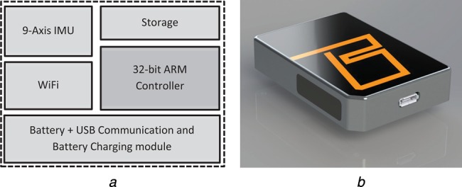
BioKin-WMS wireless motion sensor
a Block diagram representation of electronics of the motion capture device
b Photograph of prototype
2.1.1. Gait analysis PC suite
This is the most versatile software among the BioKin-GA family featuring full stand-alone operation. BioKin PC suite is a cross-platform software developed in Java, which includes sensor data collection, sensor management tools, internal/external database handling, patient management, data analysis and visualisation features. BioKin-WMS sensors can be interfaced with the PC suite via WiFi (typically for data collection) or USB for configuration via the sensor management tool. In the motion capturing process, the software communicates with multiple BioKin-WMS sensors (up to 10) via UDP packets over a WiFi network and allows users to record time-stamped data up to 140 Hz update rate on an internal database or a database located within a high speed LAN. Moreover, an external database transfer facility is provided to update central clinical databases when gathering patient data in remote locations. The gait analysis and visualisation tool provides the clinicians with kinematic data at key gait cycle points in an easy to manipulate graphical representations together with playback capabilities.
2.1.2. BioKin cloud
A cross-platform server end application to handle BioKin data. This accepts bulk transfer of patient data from the PC suite and mobile versions of the software package. The server can also act as a data analysis agent for mobile versions, where it supplies information required to recreate the 3D motion of the recorded data together with associated gait parameters.
2.1.3. BioKin-Mobi
BioKin-Mobi serves two purposes; a patient data capture tool and a data visualisation tool for clinicians. Unlike the PC suite, it does not have the data analysis capabilities and internal database management system. Instead, BioKin-Mobi stores the data temporarily until the recording is completed and then transfer the time-stamped raw data to the ‘BioKin Cloud’. Moreover, the clinician view of the mobile version requests the pre-analysed gait movement information from the cloud and provides the visual representation of the information in a similar format to the PC suite.
3. Orientation estimation and gait parameter annotation
3.1. Gait feature detection and annotation
This system performs automatic gait parameter annotation on the data stream while allowing clinicians to perform manual annotations that can be used in consecutive treatments. Automatic annotation is relied upon the identification of key gait cycle points (see Fig. 2): heel-strike (HS), flat-foot (FF), toe-off, swing-start, mid-swing (MS) and swing-end. Then, each gait cycle can be processed for any pre-configured abnormalities such as diplegic or neuropathic gait. Moreover, the kinematic data (orientation and speed of motion in each plane) is produced for each key gait cycle point and other annotated points in the data stream. Fig. 3 illustrates the movement planes used in this Letter and the IMU sensor locations (foot, shank and thigh) and their local coordinate systems for gait capture.
Figure 2.
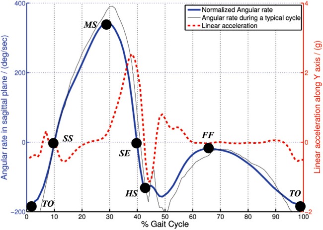
Angular rate and linear acceleration variation in gait cycle together with key gait cycle points
Figure 3.
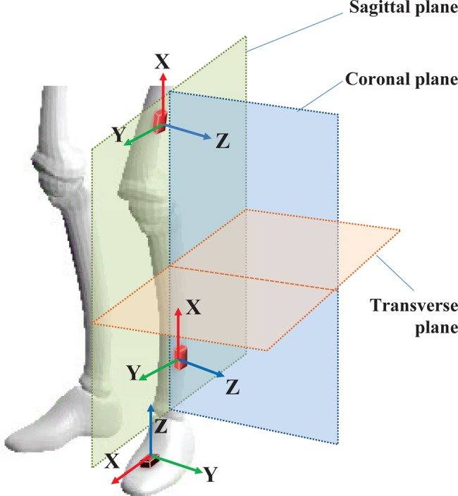
Movement planes and sensor locations for biped gait capture
Key gait cycle points are estimated from the pattern analysis of raw gyroscopic data, combined with acceleration data. The typical angular rate variation in the sagittal plane and the corresponding acceleration along the Y-axis on a shank mounted IMU (see Fig. 3) during a gait cycle is illustrated in Fig. 2. A publicly available activity data set [32] was used to derive the normalised data presented in this graph. Key gait points directly correspond to the peaks, dips and plateaus in the gyroscope data. Simple threshold and pattern analysis techniques are used to capture such points in the data stream. Note that in this figure, we used a publicly available gait data set to illustrate the key gait points and to demonstrate the similarity of existing data with the data collected with BioKin sensors.
As seen in Fig. 2, the FF state can be identified as the gait event with the least amount of movement in the sagittal plane. In such instances, the acceleration measurements are used to correct any drifts in the gyroscope integration process as well as used to calculate the ‘true’ angles in sagittal and transverse planes. This is presented in the following Section.
3.2. Orientation estimation
The limb orientation is calculated from the IMU data, together with the key-gait points to perform drift correction in the IMU calculation process. Let sqω = [0 ωX ωY ωZ] represent the raw gyroscope measurements around the respective local coordinate axis (see Fig. 3) in quaternion notation. Note that, in this Letter, we use ⊗ to represent quaternion multiplication and * to represent the conjugate of a quaternion. The rate of change of the orientation quaternion is defined as [31]
| (1) |
and the quaternion is calculated using
| (2) |
Here, is the optimal orientation quaternion, which is calculated from the following steepest gradient method [31, 33]
| (3) |
where f∇ is the objective function used in the gradient-descent algorithm, which provides the deviation of the actual accelerometer measurement vector in the sensor-frame (sqa(t)) with the rotated gravitational vector EqG using the orientation quaternion as follows
| (4) |
Here
| (5) |
is the temporal weighting function in which 0 < Q < 1 is a weighing factor that defines the dominant element among Kgp and Km. Here
is the temporal weighting function derived from the key gait events such that the function value peaks at FF locations as a Gaussian function. Here, g denotes a gait cycle, Ng is the total number of gait cycles in the data set, GF(g) represents the FF gait event of gth gait cycle and T(GF(g)) represents the time of occurrence of GF(g) event. TF(g) ⊂ [T(GF(g)) − 6 × thTgp,…,T(GF(g)) + 6 × thTgp] represents the surrounding region of a FF gait event GF(g) and tTg is a constant that defines the smoothness and spread of the Gaussian curve.
In (5), the movement-based weighing function
is used to incorporate accelerometer measurements into the orientation estimation when the normalised gyroscopic movement is less than a pre-defined threshold, i.e., , where threshold defines the upper bound of the slow movement range.
While performing sensor fusion, this method uses pre-analysed gait pattern information and gyro rate to select most appropriate weighted temporal distribution of the optimisation function. Fig. 4 illustrates the variation of Θ with gyro rate as used in the analysis of experimental data in Section 4. In Fig. 4, black dots represent the FF events in the gait cycle and green circles highlight the activation of Θ at low activity regions in the IMU data. Note that the effect of low-activity component is not visible in FF locations due to the higher weighing on Kgp.
Figure 4.
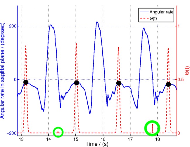
Variation of Θ in (5) with gyroscopic data and key gait cycle points
Among other optimisation algorithms, we are using gradient-descent algorithm because of its simplicity in implementation in a real-world practical system. The following equation describes the implementation of the gradient-descent algorithm
| (6) |
where
| (7) |
and 1 > μ > 0 is the step-size parameter.
Note that this Section presents an algorithm based on selective fusion of acceleration and gyroscopic data to calculate limb orientation using a gradient-descent algorithm. The selective fusion algorithm initiates only in certain instances defined by the FF event or low gyroscopic movements as defined in (5). Fusing the acceleration data with the orientation calculation process essentially re-initiate the integration of gyroscopic data at selected instances where the acceleration data provides only the gravitational forces acting upon the IMU sensor. This removes the errors accumulated during the integration of gyroscopic data and converge the orientation to the tilt angle calculated using the gravitational forces acting on different axes of the IMU. Moreover, this algorithm is quite different to other gradient-descent approaches such as [31], particularly because the selective fusion approach eliminates the fusion of acceleration data into the orientation calculation process where acceleration is highly contaminated with movement noise, i.e., fast moving instances and impacts, such as swing and HS events.
4. Experimental results and discussion
This Section provides the experimental results to illustrate the gait event detection and the orientation estimation approach presented in this Letter. Moreover, these results are compared against the ‘gold standard’ VICON optical motion capture and force-plate results.
4.1. Motion capture
The experiment was performed with a male subject without any history of orthopaedic or intramuscular impairments. The walking experiments were performed on a treadmill equipped with a force plate (BERTEC Instrumented Treadmill) and the motion was simultaneously recorded using a VICON optical motion capturing system (VICON T40S System) and BioKin. Fig. 5a shows the lab space used for this experiment and Fig. 5b shows the reflective markers attached to the subject's lower limbs. The BioKin-WMS sensors were attached to the subject's lower limb as illustrated in Fig. 5b and BioKin-GA PC suite was used to capture and store IMU data. Note that, although we have used six sensors during the data collection, only the ankle mounted sensor data were used in the analysis presented in this research. IMU data was sampled at 140 Hz, VICON coordinates were sampled at 250 Hz, while the force-plate data was recorded at 1000 Hz for the total duration of the experiment. During the analysis, VICON and force-plate data were re-sampled at 140 Hz for comparison purposes. To evaluate the performance of the algorithm with different walking speeds, the experiment was performed for three walking speeds 0.5, 1.0 and 1.5 m/s with 2 min of walking at each speed.
Figure 5.
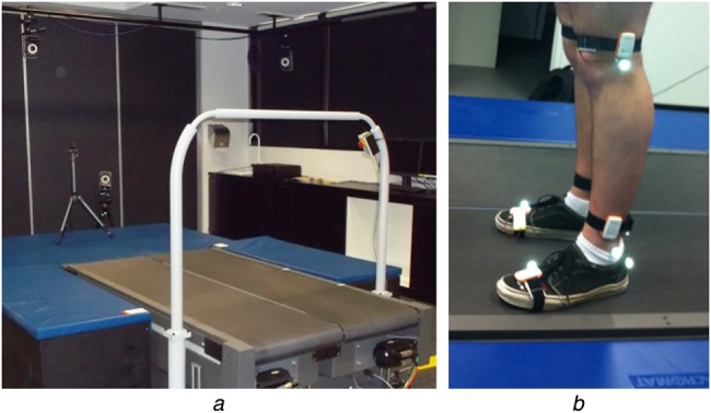
Experimental setup
a Lab spaced used for experiment
b Reflective markers attached to subject's lower limbs
4.2. Gait feature detection
Peak detection threshold of 100°/s was used to identify MS location and then pattern identification methods were used to detect other gait events. Fig. 6 illustrates the relationship between the detected points and the force-plate patterns. In traditional gait analysis systems, peaks in vertical force-plate data is used to identify HS points of the gait cycle [27] and from Fig. 6, it is clear that the force-plate peaks directly corresponds to the HS events detected by the proposed angular rate-based gait feature detection system.
Figure 6.
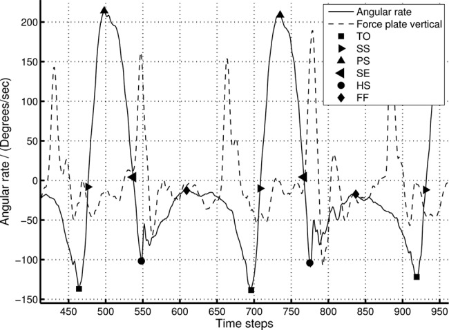
Key gait cycle point detection and comparison with force-plate data for 0.5 m/s walking speed
Note that only the z-axis force-plate data is plotted here
4.3. Orientation estimation
In this Section, we compare the sagittal orientation calculated using GCO, HPI, RI and VD methods (Table 1). Fig. 7 illustrates the angles computed using the above methods for the entire walking data set and Fig. 8 shows the zoomed section of the same data set. Since the RI and HPI orientation values do not have the correct initial state, the initial point was manually adjusted to suit the VICON angle while the GCO automatically corrects the orientation during selective fusion. Fig. 9 shows the root-mean-square error (RMSE) of the HPI and GCO orientations compared with the VICON derived angle.
Table 1.
Abbreviations
| GCO | quaternion optimisation approach incorporating key gait cycle points presented in Section 3.2 |
| HPI | integration of high-pass filtered angular rate data on a certain axis |
| RI | integration of raw angular rate data on a certain axis |
| VD | VICON derived orientation on the respective plane |
Figure 7.
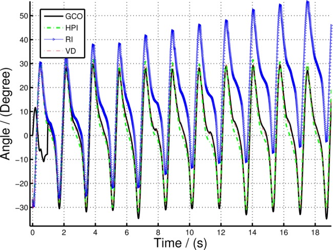
Comparing sagittal orientation of lower leg (shank) computed using GCO, HPI and RI with VD orientation for 0.5 m/s walking speed
Figure 8.
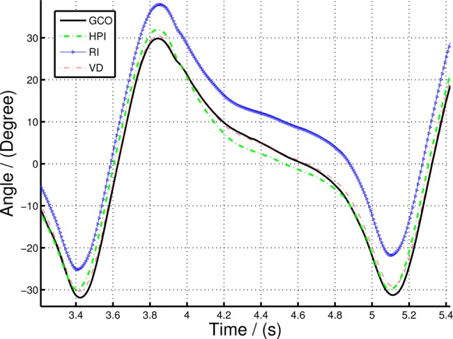
Zoomed in section of Fig. 7 to illustrate the variation of GCO and HPI orientation compared to VD
Figure 9.
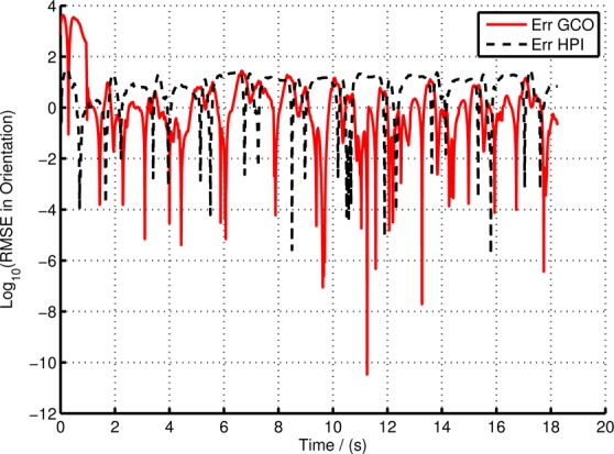
Error in GCO and HPI compared to the VD orientation in experiment with 0.5 m/s walking speed
The iterative optimisation algorithm is terminated when the magnitude of the kth iteration step
| (8) |
where υth is a threshold value or the maximum number of iterations (kNmax) reached. In this experiment, the step-size parameter μ = 0.0001, υth = 0.1 and kNmax = 1000 were selected in order to ensure smooth convergence of the iterative algorithm. The gravitational vector EqG = [0 1 0] was selected to suit the sensor measurement range and the normal orientation of the sensor (see Fig. 3). The weighing factor Q in (5) and the threshold values tTg and mgth are selected as 0.1, 20 and 5, respectively. The cut-off frequency for the high-pass filter was selected as 0.065 Hz.
It is clear from Figs. 7 and 8 that there is a significant divergence of the RI orientation compared to the actual VD orientation because of the inherent gyro drift. The high-pass filtered orientation provides a significant improvement in drift mitigation compared to the RI orientation, closely tracking the VD orientation. However, the HPI orientation deviates from the VD orientations in slow moving instances (e.g. FF event), since the high-pass filter itself eliminates the slow changes in the gyro-rate data, making it to move to ‘zero’ angular rate at such events. On the other hand, the GCO angles provide more accurate results at slow moving instances, in fact, it corrects any errors at such instances by fusing the acceleration data with the orientation algorithm. Fig. 8 illustrates this statement. The GCO algorithm fuses the acceleration data only at certain instances defined by Θ function which takes at least one gait cycle to initiate, thus having large errors at the beginning of the walking data series. However, once the sensor fusion algorithm initiates, the orientation corrects itself with respect to gravity. This is illustrated in Fig. 9. Note that the error in Fig. 9 represented in log scale, such that all the variations are clearly illustrated. Particularly, the large deviations in the GCO orientation during the first gait cycle.
The average RMSE values and the correlation coefficient (CC) of GCO and HPI compared with VD orientation are shown in Table 2. Note that since the HPIs initial state is manually created, in order to maintain the generality, the results shown in Table 2 were calculated using data points after the first gait cycle, i.e., after the GCO approach reached the initial sensor fusion point. With this initial result for a single subject comparing the aforementioned gait orientation algorithm with ‘gold standard’ provides evidence that this approach can be used for assessment of gait kinematics in non-clinical environments. Both GCO and HPI methods provide strong correlation (>95%) for all three speed settings. However, given that the results presented here were for a single subject without a history of orthopaedic or intramuscular impairments, no conclusion can be drawn at this stage as to whether this approach is suitable for general patient assessment. Clinical trials targeting specific medical conditions such as cerebral palsy, stroke, Parkinson's disease etc. with a larger patient group will help one to understand the validity of this approach in clinical assessment.
Table 2.
Experimental results
| Speed | 0.5 m/s | 1.0 m/s | 1.5 m/s | |||
|---|---|---|---|---|---|---|
| Method | HPI | GCO | HPI | GCO | HPI | GCO |
| RMSE1 | 2.33 | 1.15 | 3.32 | 3.24 | 3.78 | 3.56 |
| CC | 0.998 | 0.991 | 0.987 | 0.974 | 0.968 | 0.957 |
RMSE in degrees.
5. Concluding remarks
In this Letter, we presented an ambulatory gait analysis platform, BioKin™, which includes: low-cost wearable motion capture sensors and a software suite to store, process and visualise gait kinematics. Moreover, we introduced a selective sensor fusion algorithm to estimate limb orientation by fusing gyroscopic and acceleration sensor data from the IMU. The fusion algorithm effectively compensates the drift accumulated during the angular rate integration using acceleration data at selected instances. The proposed algorithm was tested with experimental data against an industry standard optical motion tracking system and the accuracy was verified. BioKin™ is a potential platform for clinicians to collect data to augment gait analysis in remote clinical locations, i.e., away from the well-equipped gait laboratories, particularly when the patients require routine gait kinematic evaluation to plan and evaluate the outcome of therapeutic interventions. Future studies will be focused on the capture and analysis of gait patterns related to the specific medical condition such as Parkinson's disease, stroke, cerebral palsy etc. and extending the motion analysis for full-body kinematics.
6. Funding and declaration of interests
This work was jointly supported by Deakin University and National ICT Australia (NICTA). Dr. Ekanayake reports personal fees from National ICT Australia during the conduct of this study.
7 References
- 1.Whittle M.W.: ‘Gait analysis: an introduction’ (Butterworth-Heinemann, Oxford, UK, 2007, 4th edn.) [Google Scholar]
- 2.Palisano R., Rosenbaum P., Walter S., Russell D., Wood E., Galuppi B.: ‘Development and reliability of a system to classify gross motor function in children with cerebral palsy’, Dev. Med. Child Neurol., 1997, 39, (4), pp. 214–223 (doi: ) [DOI] [PubMed] [Google Scholar]
- 3.Chang F.M., Seidl A.J., Muthusamy K., Meininger A.K., Carollo J.J.: ‘Effectiveness of instrumented gait analysis in children with cerebral palsy – comparison of outcomes’, J. Pediatr. Orthop., 2006, 26, (5), pp. 612–616 (doi: ) [DOI] [PubMed] [Google Scholar]
- 4.Lee E.H., Goh J.C., Bose K.: ‘Value of gait analysis in the assessment of surgery in cerebral palsy’, Arch. Phys. Med. Rehabil., 1992, 73, (7), pp. 642–646 [PubMed] [Google Scholar]
- 5.Sutherland D.H.: ‘The evolution of clinical gait analysis. Part ii kinematics’, Gait Posture, 2002, 16, (2), pp. 159–179 (doi: ) [DOI] [PubMed] [Google Scholar]
- 6.Sutherland D.H.: ‘The evolution of clinical gait analysis. Part III – kinetics and energy assessment’, Gait Posture, 2005, 21, (4), pp. 447–461 (doi: ) [DOI] [PubMed] [Google Scholar]
- 7.Webster K.E., Wittwer J.E., Feller J.A.: ‘Validity of the GAITRite walkway system for the measurement of averaged and individual step parameters of gait’, Gait Posture, 2005, 22, (4), pp. 317–321 (doi: ) [DOI] [PubMed] [Google Scholar]
- 8.DeLisa J., Kerrigan C.: ‘Gait analysis in the science of rehabilitation’ (Diane Publishing Company, Collingdale, USA, 2000) [Google Scholar]
- 9.Moeslund T.B., Granum E.: ‘A survey of computer vision-based human motion capture’, Comput. Vis. Image Understand., 2001, 81, (3), pp. 231–268 (doi: ) [Google Scholar]
- 10.Sutherland D.H.: ‘The evolution of clinical gait analysis part l: kinesiological EMG’, Gait Posture, 2001, 14, (1), pp. 61–70 (doi: ) [DOI] [PubMed] [Google Scholar]
- 11.Riley P.O., Paolini G., Croce U.D., Paylo K.W., Kerrigan D.C.: ‘A kinematic and kinetic comparison of overground and treadmill walking in healthy subjects’, Gait Posture, 2007, 26, (1), pp. 17–24 (doi: ) [DOI] [PubMed] [Google Scholar]
- 12.Caderby T., Yiou E., Peyrot N., Bonazzi B., Dalleau G.: ‘Detection of swing heel-off event in gait initiation using force-plate data’, Gait Posture, 2013, 37, (3), pp. 463–466 (doi: ) [DOI] [PubMed] [Google Scholar]
- 13.Aminian K., Trevisan C., Najafi B., et al. : ‘Evaluation of an ambulatory system for gait analysis in hip osteoarthritis and after total hip replacement’, Gait Posture, 2004, 20, (1), pp. 102–107 (doi: ) [DOI] [PubMed] [Google Scholar]
- 14.Salarian A., Russmann H., Vingerhoets F.J.G., et al. : ‘Gait assessment in Parkinson's disease: toward an ambulatory system for long-term monitoring’, IEEE Trans. Biomed. Eng., 2004, 51, (8), pp. 1434–1443 (doi: ) [DOI] [PubMed] [Google Scholar]
- 15.Rong Chen B., Patel S., Buckley T., et al. : ‘A web-based system for home monitoring of patients with parkinson's disease using wearable sensors’, IEEE Trans. Biomed. Eng., 2011, 58, (3), pp. 831–836 (doi: ) [DOI] [PubMed] [Google Scholar]
- 16.Zhang M., Sawchuk A.: ‘Human daily activity recognition with sparse representation using wearable sensors’, IEEE J. Biomed. Health Informatics, 2013, 17, (3), pp. 553–560 (doi: ) [DOI] [PubMed] [Google Scholar]
- 17.Villarroel M., Guazzi A., Jorge J., et al. : ‘Continuous non-contact vital sign monitoring in neonatal intensive care unit’, Healthc. Technol. Lett., 2014, 1, (3), pp. 87–91 (doi: ) [DOI] [PMC free article] [PubMed] [Google Scholar]
- 18.Sabatini A., Martelloni C., Scapellato S., Cavallo F.: ‘Assessment of walking features from foot inertial sensing’, IEEE Trans. Biomed. Eng., 2005, 52, (3), pp. 486–494 (doi: ) [DOI] [PubMed] [Google Scholar]
- 19.Bamberg S.J.M., Benbasat A.Y., Scarborough D.M., Krebs D.E., Paradiso J.A.: ‘Gait analysis using a shoe-integrated wireless sensor system’, IEEE Trans. Inf. Technol. Biomed., 2008, 12, (4), pp. 413–423 (doi: ) [DOI] [PubMed] [Google Scholar]
- 20.Kyoungchul K., Tomizuka M.: ‘A gait monitoring system based on air pressure sensors embedded in a shoe’, IEEE/ASME Trans. Mechatronics, 2009, 14, (3), pp. 358–370 (doi: ) [Google Scholar]
- 21.Schepers H.M., Koopman H.F.J.M., Veltink P.H.: ‘Ambulatory assessment of ankle and foot dynamics’, IEEE Trans. Biomed. Eng., 2007, 54, (5), pp. 895–902 (doi: ) [DOI] [PubMed] [Google Scholar]
- 22.Veltink P.H., Liedtke C., Droog E., van der Kooij H.: ‘Ambulatory measurement of ground reaction forces’, IEEE Trans. Neural Syst. Rehabil. Eng., 2005, 13, (3), pp. 423–427 (doi: ) [DOI] [PubMed] [Google Scholar]
- 23.Razian M.A., Pepper M.G.: ‘Design, development, and characteristics of an in-shoe triaxial pressure measurement transducer utilizing a single element of piezoelectric copolymer film’, IEEE Trans. Neural Syst. Rehabil. Eng., 2003, 11, (3), pp. 288–293 (doi: ) [DOI] [PubMed] [Google Scholar]
- 24.Ketteringham L.P., Western D.G., Neild S.A., Hyde R.A., Jones R.J., Davies-Smith A.M.: ‘Inverse dynamics modelling of upper-limb tremor, with cross-correlation analysis’, Healthc. Technol. Lett., 2014, 1, (2), pp. 59–63 (doi: ) [DOI] [PMC free article] [PubMed] [Google Scholar]
- 25.Aminian K., Najafi B., BÃijla C., Leyvraz P.F., Robert P.: ‘Spatio-temporal parameters of gait measured by an ambulatory system using miniature gyroscopes’, J. Biomechanics, 2002, 35, (5), pp. 689–699 (doi: ) [DOI] [PubMed] [Google Scholar]
- 26.Tong K., Granat M.H.: ‘A practical gait analysis system using gyroscopes’, Med. Eng. Phys., 1999, 21, (2), pp. 87–94 (doi: ) [DOI] [PubMed] [Google Scholar]
- 27.O'Connor C.M., Thorpe S.K., O'Malley M.J., Vaughan C.L.: ‘Automatic detection of gait events using kinematic data’, Gait Posture, 2007, 25, (3), pp. 469–474 (doi: ) [DOI] [PubMed] [Google Scholar]
- 28.Zhang R., Hoflinger F., Reindl L.: ‘Inertial sensor based indoor localization and monitoring system for emergency responders’, IEEE Sens. J., 2013, 13, (2), pp. 838–848 (doi: ) [Google Scholar]
- 29.Zhang Z.-Q., Wong W.-C., Wu J.-K.: ‘Ubiquitous human upper-limb motion estimation using wearable sensors’, IEEE Trans. Inf. Technol. Biomed., 2011, 15, (4), pp. 513–521 (doi: ) [DOI] [PubMed] [Google Scholar]
- 30.3D Optical Motion Capture. Available at: http://www.vicon.com
- 31.Madgwick S., Harrison A.J.L., Vaidyanathan R.: ‘Estimation of IMU and MARG orientation using a gradient descent algorithm’. Singapore, August 2011 IEEE Int. Conf. on Rehabilitation Robotics (ICORR), Singapore, August 2011, pp. 1–7 [DOI] [PubMed] [Google Scholar]
- 32.Reiss A., Stricker D.: ‘Introducing a new benchmarked dataset for activity monitoring’. The 16th IEEE Int. Symp. on Wearable Computers, Newcastle, UK, June 2012 [Google Scholar]
- 33.Dixon L.C.W.: ‘Nonlinear optimization’ (English Universities Press, 1972) [Google Scholar]


