Common artifacts in body MR imaging are presented by using basic MR physics principles, and solutions are proposed when possible, with recognition of the trade-offs and limitations inherent in each potential solution.
Abstract
Body magnetic resonance (MR) imaging is challenging because of the complex interaction of multiple factors, including motion arising from respiration and bowel peristalsis, susceptibility effects secondary to bowel gas, and the need to cover a large field of view. The combination of these factors makes body MR imaging more prone to artifacts, compared with imaging of other anatomic regions. Understanding the basic MR physics underlying artifacts is crucial to recognizing the trade-offs involved in mitigating artifacts and improving image quality. Artifacts can be classified into three main groups: (a) artifacts related to magnetic field imperfections, including the static magnetic field, the radiofrequency (RF) field, and gradient fields; (b) artifacts related to motion; and (c) artifacts arising from methods used to sample the MR signal. Static magnetic field homogeneity is essential for many MR techniques, such as fat saturation and balanced steady-state free precession. Susceptibility effects become more pronounced at higher field strengths and can be ameliorated by using spin-echo sequences when possible, increasing the receiver bandwidth, and aligning the phase-encoding gradient with the strongest susceptibility gradients, among other strategies. Nonuniformities in the RF transmit field, including dielectric effects, can be minimized by applying dielectric pads or imaging at lower field strength. Motion artifacts can be overcome through respiratory synchronization, alternative k-space sampling schemes, and parallel imaging. Aliasing and truncation artifacts derive from limitations in digital sampling of the MR signal and can be rectified by adjusting the sampling parameters. Understanding the causes of artifacts and their possible solutions will enable practitioners of body MR imaging to meet the challenges of novel pulse sequence design, parallel imaging, and increasing field strength.
©RSNA, 2015
SA-CME LEARNING OBJECTIVES
After completing this journal-based SA-CME activity, participants will be able to:
■ Discuss the causes of common artifacts seen on body MR images by using basic MR physics principles.
■ Identify solutions for artifacts seen on body MR images.
■ Recognize the trade-offs and limitations inherent in each potential solution.
Introduction
Body magnetic resonance (MR) imaging is challenging because of the complex interplay of myriad factors. These factors include (a) motion arising from respiration, bowel peristalsis, and cardiac and vascular pulsation; (b) signal loss from susceptibility effects secondary to bowel gas; and (c) the demands posed by the need to cover a large field of view (FOV). Some of these issues are exacerbated at higher field strengths (eg, 3 T). A better understanding of the causes of artifacts within the complex environment of body MR imaging is integral to improving the practice of such imaging and meeting the challenges of novel pulse sequence design, parallel transmission, and increasing field strength.
In this article, case examples of artifacts associated with body MR imaging at both 1.5 T and 3 T are provided and categorized on the basis of motion, magnetic field sensitivity profiles, field strength, chemical shift, spatial encoding, pulse sequence, coil type, location, and parallel imaging. The explanations for these artifacts use basic MR physics principles, including k-space encoding and signal processing principles. Solutions are proposed when possible.
The purpose of this article is to update and familiarize the reader with the range of artifacts seen at body MR imaging at 1.5 T and 3 T and to explain the causes of these artifacts from the standpoint of basic MR physics principles, to find solutions and improve image quality. First, artifacts caused by magnetic field imperfections are covered, followed by motion artifacts. Finally, artifacts related to image digitization and postprocessing are discussed.
Artifacts Caused by Magnetic Field Imperfections
At the heart of MR image creation is the interaction of nuclear spins with magnetic fields. Magnetic field sources include the static magnetic field (B0) responsible for generating the magnetization, the applied radiofrequency (RF) fields (B1) for manipulating the magnetization, and magnetic field gradients for spatial encoding. MR image acquisition relies on several assumptions, including the presence of a homogeneous B0 field, well-defined spatial RF excitation profiles, and spatially linear gradient fields. Deviations from these assumptions may give rise to artifacts within an image.
Static Magnetic Field Artifacts
Description.—MR imaging and MR spectroscopy depend on a homogeneous static magnetic field (B0). According to the Larmor relationship, the spin precession frequency ω is directly proportional to the strength of the magnetic field B0 according to the following equation: ω = γ B0, where γ is the gyromagnetic ratio. MR image acquisition assumes that B0 does not vary in space. The imaging magnetic field gradients induce frequency shifts that relate directly to the spatial location of the spins. Local field gradients that arise from the object that is being imaged cause B0 to be nonuniform. B0 inhomogeneity may cause spatial distortions when the inhomogeneity is large by assigning the signal origin to the wrong location on the basis of differences between the assumed and the actual resonance frequency. When B0 inhomogeneity is small, it can give rise to other problems related to the accumulation of phase offsets caused by resonance frequency differences (see “B0-Sensitive Banding Artifacts”).
In contrast, at MR spectroscopy, inhomogeneity in the magnetic field causes spectral line broadening and impairs separation of spectral frequencies arising from different chemical species. B0 inhomogeneity at both MR spectroscopy and MR imaging can also lead to inadequate fat suppression at body MR imaging (see “Fat Suppression”).
Solutions.—Artifacts induced by B0 inhomogeneity can be remedied with improved shimming, which corrects spatial variations in the static magnetic field.
Susceptibility Artifacts
Description.—In addition to the external magnetic field, spins are subject to the internal magnetic fields induced in the tissues in which they reside. Magnetic susceptibility represents the degree to which a material develops magnetization of its own when placed in an external magnetic field (1). Paramagnetic substances strengthen the local magnetic field, and diamagnetic substances weaken the local magnetic field. Susceptibility effects are most pronounced at interfaces between materials with extremely different susceptibilities that produce large spatial variations in the local magnetic field (eg, air-tissue, bone-tissue, and metal-tissue interfaces).
Artifacts related to susceptibility can manifest as localized distortions and/or signal loss in areas in which the bulk magnetization has been altered dramatically. Susceptibility changes result in frequency shifts that are due to differences in the local magnetic field that cause the spins to precess at different frequencies. The effects are twofold: (a) Changes in the local magnetic field induced by susceptibility differences lead to faulty spatial mapping and image distortion in the frequency-encoding direction; and (b) accelerated spin dephasing leads to signal loss near boundaries between substances with differing susceptibilities.
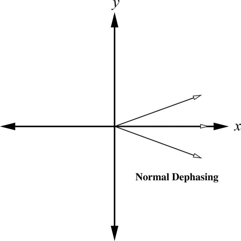
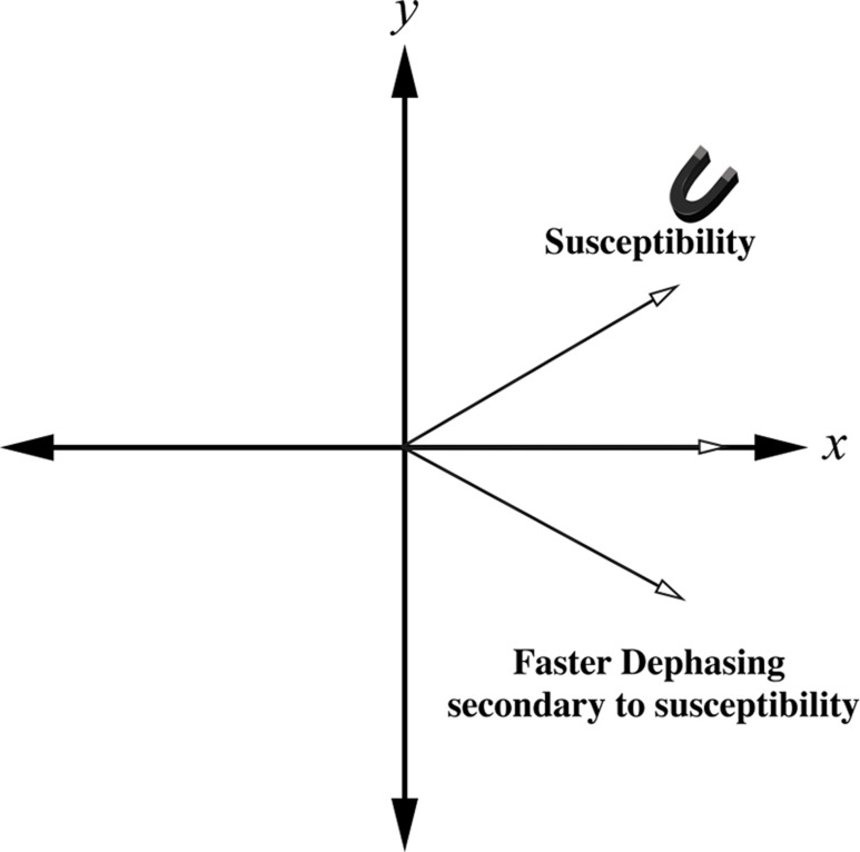
Spin dephasing induced by materials with differing susceptibilities increases with readout time. Because the MR signal dephases faster with decreasing transverse relaxation time affected by magnetic field heterogeneity (T2*) (2), gradient-echo sequences and single-shot echo-planar imaging (in which the whole of k-space is sampled in an extended readout period after a single RF preparation) are more sensitive to susceptibility effects (Fig 1). On the other hand, spin-echo imaging that uses 180° RF pulses to refocus spin dephasing caused by magnetic field inhomogeneities is not as sensitive to these changes in susceptibility. Susceptibility artifacts are also exacerbated at higher field strengths because frequency variations increase in proportion to field strength (3–5).
Figure 1a.
Schematic diagrams show the effect of susceptibility gradients on spin precession. (a) In the absence of susceptibility gradients, spin dephasing is governed by T2 relaxation. (b) The presence of susceptibility gradients accelerates spin dephasing, which leads to signal loss near boundaries between materials of differing susceptibilities.
Figure 1b.
Schematic diagrams show the effect of susceptibility gradients on spin precession. (a) In the absence of susceptibility gradients, spin dephasing is governed by T2 relaxation. (b) The presence of susceptibility gradients accelerates spin dephasing, which leads to signal loss near boundaries between materials of differing susceptibilities.
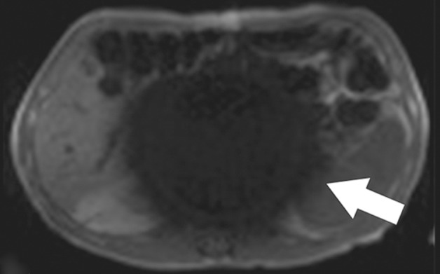
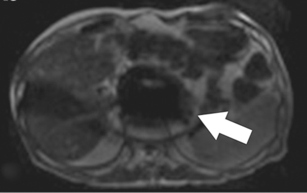
Solutions.—Approaches to minimizing susceptibility artifacts include (a) adjusting pulse sequence and acquisition parameters to decrease spin dephasing; (b) increasing receiver bandwidth to reduce the relative contribution of signal distortion to the overall image; (c) changing k-space sampling techniques; and (d) changing field strength. Specific solutions for susceptibility artifacts are spin-echo imaging, shortening the echo time, decreasing the voxel size, increasing receiver bandwidth, aligning the phase-encoding direction with susceptibility gradients, radial sampling, parallel imaging (increasing the percentage of k-space filling), partial k-space sequences, and lower field strength. The spin-echo sequence is one of the best ways to reduce susceptibility artifacts (Fig 2). Shortening the echo time can also markedly ameliorate susceptibility artifact by allowing less time for spin dephasing to occur.
Figure 2a.
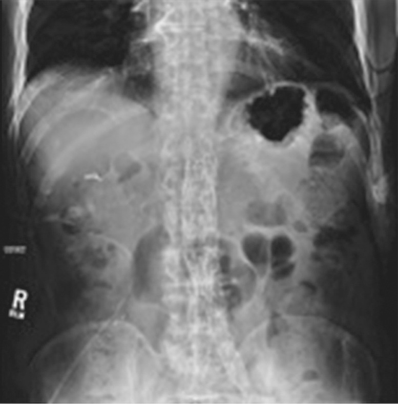
Susceptibility artifact in a 65-year-old man who had undergone endovascular repair of an abdominal aortic aneurysm. (a, b) Coronal balanced steady-state free precession (SSFP) (a) and axial gradient-echo (b) MR images of the abdomen show marked signal loss (arrow in b) caused by spin dephasing near the metallic aortic stent-graft. (c) Axial T2-weighted MR image of the abdomen was acquired with a fast spin-echo sequence. Both the balanced SSFP sequence used in a, which has T2* and T1 weighting, and the gradient-echo sequence used in b are more sensitive to susceptibility artifacts than the fast spin-echo sequence used in c. Arrow = location of signal loss in b. (d) Kidney, ureter, bladder posteroanterior radiograph shows the metallic components of the aortic stent-graft.
Figure 2b.
Susceptibility artifact in a 65-year-old man who had undergone endovascular repair of an abdominal aortic aneurysm. (a, b) Coronal balanced steady-state free precession (SSFP) (a) and axial gradient-echo (b) MR images of the abdomen show marked signal loss (arrow in b) caused by spin dephasing near the metallic aortic stent-graft. (c) Axial T2-weighted MR image of the abdomen was acquired with a fast spin-echo sequence. Both the balanced SSFP sequence used in a, which has T2* and T1 weighting, and the gradient-echo sequence used in b are more sensitive to susceptibility artifacts than the fast spin-echo sequence used in c. Arrow = location of signal loss in b. (d) Kidney, ureter, bladder posteroanterior radiograph shows the metallic components of the aortic stent-graft.
Figure 2c.
Susceptibility artifact in a 65-year-old man who had undergone endovascular repair of an abdominal aortic aneurysm. (a, b) Coronal balanced steady-state free precession (SSFP) (a) and axial gradient-echo (b) MR images of the abdomen show marked signal loss (arrow in b) caused by spin dephasing near the metallic aortic stent-graft. (c) Axial T2-weighted MR image of the abdomen was acquired with a fast spin-echo sequence. Both the balanced SSFP sequence used in a, which has T2* and T1 weighting, and the gradient-echo sequence used in b are more sensitive to susceptibility artifacts than the fast spin-echo sequence used in c. Arrow = location of signal loss in b. (d) Kidney, ureter, bladder posteroanterior radiograph shows the metallic components of the aortic stent-graft.
Figure 2d.
Susceptibility artifact in a 65-year-old man who had undergone endovascular repair of an abdominal aortic aneurysm. (a, b) Coronal balanced steady-state free precession (SSFP) (a) and axial gradient-echo (b) MR images of the abdomen show marked signal loss (arrow in b) caused by spin dephasing near the metallic aortic stent-graft. (c) Axial T2-weighted MR image of the abdomen was acquired with a fast spin-echo sequence. Both the balanced SSFP sequence used in a, which has T2* and T1 weighting, and the gradient-echo sequence used in b are more sensitive to susceptibility artifacts than the fast spin-echo sequence used in c. Arrow = location of signal loss in b. (d) Kidney, ureter, bladder posteroanterior radiograph shows the metallic components of the aortic stent-graft.
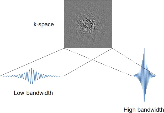
Increasing the receiver bandwidth (in hertz per pixel) decreases susceptibility artifact by reducing the relative contribution of spin dephasing to the overall signal. B0 field sensitivity depends on the time duration of the MR signal sampling. The longer the duration of sampling, the more time is allowed for the magnetization to evolve (Fig 3). In the presence of B0 inhomogeneities caused by the static field, tissue susceptibility, or even chemical shift, a “low” sampling bandwidth will produce greater artifacts than a “high” sampling bandwidth. On the other hand, low bandwidth sampling will have less noise and a better SNR. Increasing the bandwidth shortens the readout interval and allows a shorter echo time to also be achieved at the expense of a lower SNR.
Figure 3.
Sampling bandwidth and B0 artifact. B0 field sensitivity depends on the time duration of the MR signal sampling. The longer the duration of sampling, the more time is allowed for the magnetization to evolve. In the presence of B0 inhomogeneities caused by the static field, by tissue susceptibility, or even by chemical shift, a “low” sampling bandwidth will produce greater artifacts than a “high” sampling bandwidth. On the other hand, low bandwidth sampling will have less noise and a better signal-to-noise ratio (SNR).
Susceptibility artifact can also be decreased close to areas of large susceptibility changes, such as those induced by metallic clips or implants, by decreasing the voxel size in the frequency-encoding and section directions. This decrease can be achieved by increasing the matrix size in the frequency-encoding direction and decreasing section thickness. Recently, three-dimensional techniques have been developed that are resistant to metal-induced susceptibility artifact, including section encoding for metal artifact correction (SEMAC; Siemens Healthcare, Malvern, Pa) (6) and multiacquisition variable-resonance image combination (MAVRIC; GE Healthcare, Waukesha, Wis) (7). The SEMAC technique corrects for distortions induced by metal-induced field inhomogeneities within the imaging plane through an extended view angle–tilting spin-echo sequence and uses additional z-phase encoding to correct for distorted excitation profiles that cause distortion between imaging sections. The MAVRIC technique uses multiple three-dimensional acquisitions with different resonance frequency offsets and then sums the off-resonance images for each section to account for susceptibility-induced frequency offsets.
The magnetic susceptibility induced by an object varies depending on its orientation relative to the static magnetic field B0. In general, susceptibility effects are more pronounced parallel to B0 than perpendicular to B0. Susceptibility artifacts can be minimized by taking advantage of the directionality of the susceptibility gradients. Aligning the phase-encoding gradient with the strongest susceptibility gradients reduces the effect of local magnetic field changes in the more sensitive frequency-encoding direction. Similarly, radial k-space sampling is invariant with respect to the orientation of susceptibility gradients and can dramatically reduce image distortions (1) (as more fully discussed in “Motion Artifacts”).
Other k-space sampling methods minimize susceptibility artifacts by parceling out the readout time into several subsets. Distortions at echo-planar imaging can be reduced by applying parallel imaging techniques to accelerate image acquisition or using partial k-space acquisition methods to reduce the amount of spatial frequency data to be acquired and, hence, the echo time, at the cost of a reduced SNR (see “Echo-Planar Imaging Artifacts”).
Imaging at a lower static magnetic field strength can also minimize susceptibility effects. Lower B0 reduces the induced magnetic field within a substance and thereby decreases the local magnetic field distortion caused by magnetic susceptibility differences.
B0-Sensitive Banding Artifacts
Description.—Balanced SSFP techniques are a special class of rapid gradient-echo sequences that are commonly used at cardiac cine imaging and MR angiography without contrast material enhancement. Balanced SSFP is finding increased use at body MR imaging because of the advantages of rapid image acquisition and a relatively high SNR (8). Specific applications of balanced SSFP for the abdomen and pelvis include those requiring high contrast between water-containing substances and the surrounding anatomy, such as MR enterography and MR cholangiopancreatography.
In balanced SSFP, the dephasing induced by the imaging gradients within each repetition time (TR) interval is refocused or balanced, which results in a single coherent transverse magnetization vector at the end of each TR. Because balanced SSFP techniques require complete reversal of the signal phase accumulated during the acquisition, they are particularly sensitive to off-resonance effects from B0 nonuniformity that induces the phase shifts and phase accumulation during the acquisition. This sensitivity to phase errors results in bandlike signal loss in areas of increased B0 nonuniformity, such as near the edges of the FOV and at tissue interfaces close to the gastrointestinal tract and lungs (Fig 4), a finding that is distinct from susceptibility artifacts.
Figure 4a.
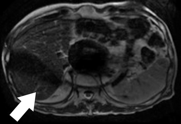
Banding artifacts. (a) Axial balanced SSFP MR image of the liver of a patient who had undergone endovascular repair of an abdominal aortic aneurysm shows a banding artifact (arrow) in the upper part of the abdomen. (b) Coronal balanced SSFP MR image of the upper part of the abdomen of a different patient shows banding artifacts (arrow) near the edges of the FOV. (c) Coronal T2-weighted MR image of the upper part of the abdomen of the same patient as in b acquired with the half-Fourier RARE sequence does not show the banding artifacts depicted in b.
Figure 4b.
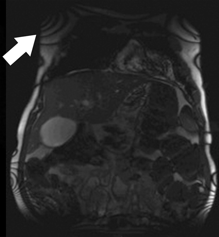
Banding artifacts. (a) Axial balanced SSFP MR image of the liver of a patient who had undergone endovascular repair of an abdominal aortic aneurysm shows a banding artifact (arrow) in the upper part of the abdomen. (b) Coronal balanced SSFP MR image of the upper part of the abdomen of a different patient shows banding artifacts (arrow) near the edges of the FOV. (c) Coronal T2-weighted MR image of the upper part of the abdomen of the same patient as in b acquired with the half-Fourier RARE sequence does not show the banding artifacts depicted in b.
Figure 4c.
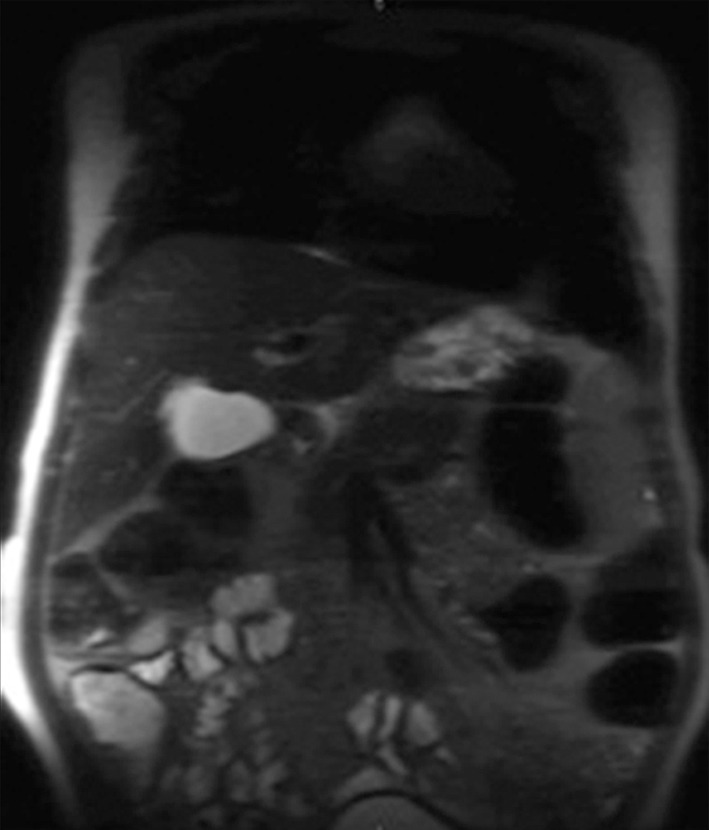
Banding artifacts. (a) Axial balanced SSFP MR image of the liver of a patient who had undergone endovascular repair of an abdominal aortic aneurysm shows a banding artifact (arrow) in the upper part of the abdomen. (b) Coronal balanced SSFP MR image of the upper part of the abdomen of a different patient shows banding artifacts (arrow) near the edges of the FOV. (c) Coronal T2-weighted MR image of the upper part of the abdomen of the same patient as in b acquired with the half-Fourier RARE sequence does not show the banding artifacts depicted in b.
The banding artifacts occur at frequency intervals of 1/TR and become more pronounced and increased in number with longer TR. Banding artifacts also tend to be worse at higher field strengths because of the proportional increase in the Larmor precession frequency. This effect is further exacerbated at higher field strengths because of limitations in the minimum allowable TR secondary to tissue energy deposition and increased susceptibility effects.
Solutions.—To ameliorate the banding artifacts, the TR is typically minimized, with the lower limit on the TR set by gradient performance and specific absorption rate considerations. For extremely short values of the TR, the spatial resolution may need to be compromised as a result of reducing the time allowed for readout in the frequency-encoding direction. Because banding artifacts appear as a result of off-resonance effects, improved shimming can also mitigate the appearance of these artifacts.
Echo-planar Imaging Artifacts
Description.—Echo-planar imaging is a fast MR acquisition technique with image acquisition times on the order of a few tens of milliseconds. Developed by Mansfield (9) in 1977, echo-planar imaging has found widespread use in diffusion, perfusion, functional, cardiac, and dynamic MR imaging because of its relative robustness to motion degradation. Within the abdomen, echo-planar imaging is used almost exclusively for diffusion-weighted imaging.
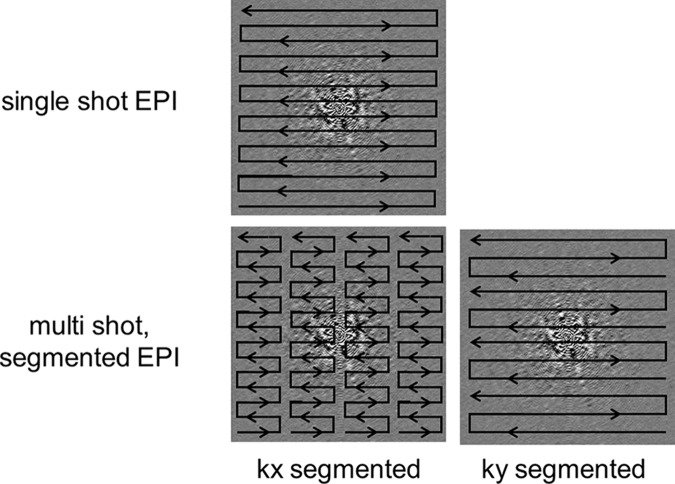
Echo-planar imaging differs from conventional gradient-echo and spin-echo sequences in the way that the readout and phase-encoding gradients are applied. At single-shot echo-planar imaging, the entirety of k-space is filled by a continuous gradient-echo train after a single RF preparation (Fig 5). This filling is achieved through a series of bipolar readout gradients and constant or blipped phase-encoding gradients, leading to either zigzag or stepwise k-space sampling trajectories, respectively. The main advantage of echo-planar imaging is extremely fast image acquisition, which protects against motion artifacts. Disadvantages include susceptibility-induced distortions at tissue interfaces and the relatively low spatial resolution, which is further limited by the T2* decay of the signal during the gradient-echo readout. As described previously, these shortcomings make echo-planar imaging extremely sensitive to B0 inhomogeneity.
Figure 5.
Segmented echo-planar imaging. A drawback to single-shot echo-planar imaging (EPI) is its sensitivity to B0 inhomogeneities that lead to image distortions. One way to mitigate this sensitivity is to perform multishot or segmented echo-planar imaging. Segmentation can be done either in the kx direction or the ky direction.
Echo-planar imaging is unique among imaging techniques in that the field-sensitive direction is the phase-encoding direction. Rapid sampling of k-space requires strong gradients with a large receiver bandwidth in the frequency-encoding direction to acquire the echoes with high temporal efficiency. In comparison, the bandwidth in the phase-encoding direction is much smaller because the transverse magnetization is continuously sampled throughout the acquisition. As a result, the phase-encoding direction is much more sensitive to small offsets in frequency from B0 nonuniformities accumulated during the long gradient-echo readout. The implication is that image distortion, which can be induced by B0 inhomogeneity, susceptibility artifacts, and/or eddy currents arising from strong diffusion-encoding gradients, tends to be more pronounced with echo-planar imaging, compared with conventional acquisitions, and in the phase-encoding direction, in contrast to the frequency-encoding direction with conventional techniques.
Solutions.—Strategies to minimize the distortion artifacts at echo-planar imaging are targeted at decreasing the total echo-planar readout time. Parallel imaging techniques such as sensitivity-encoded (SENSE; Philips Healthcare, Andover, Mass) MR imaging (10) or the generalized autocalibrated partially parallel acquisition (GRAPPA; Siemens Healthcare) (11) technique can be used to reduce the echo train length and decrease the sensitivity of the echo-planar imaging readout to B0 inhomogeneity. Spatial resolution can also be improved with parallel imaging.
Alternatively, by using multishot RF preparations, the echo-planar readout can be segmented in k-space into several portions with a shorter echo train length than the original single-shot readout (12). Segmentation can be done either in the kx or ky direction (Fig 5). The shorter signal readout durations lead to less distortion but come at the expense of imaging time. The overall acquisition time is increased because of the need to wait between repetitions of each multishot acquisition, with TR typically on the order of seconds. This increased acquisition time can also lead to increased motion artifacts. However, introducing navigator correction schemes into segmented echo-planar imaging readouts can help to decrease potential motion artifacts (13) (see “Motion Artifacts”).
Aside from sequence alterations, proper shimming to minimize B0 inhomogeneity is always essential (Fig 6). A simple way to minimize echo-planar image distortion caused by susceptibility variations is to orient the phase-encoding gradients perpendicular to the direction of the strongest susceptibility gradients. Advances in gradient hardware can also be incorporated to decrease echo-planar imaging–related artifacts by increasing the readout speeds. Furthermore, improved gradient systems with reduced eddy current effects can decrease geometric distortions, as discussed in the following paragraphs.
Figure 6a.
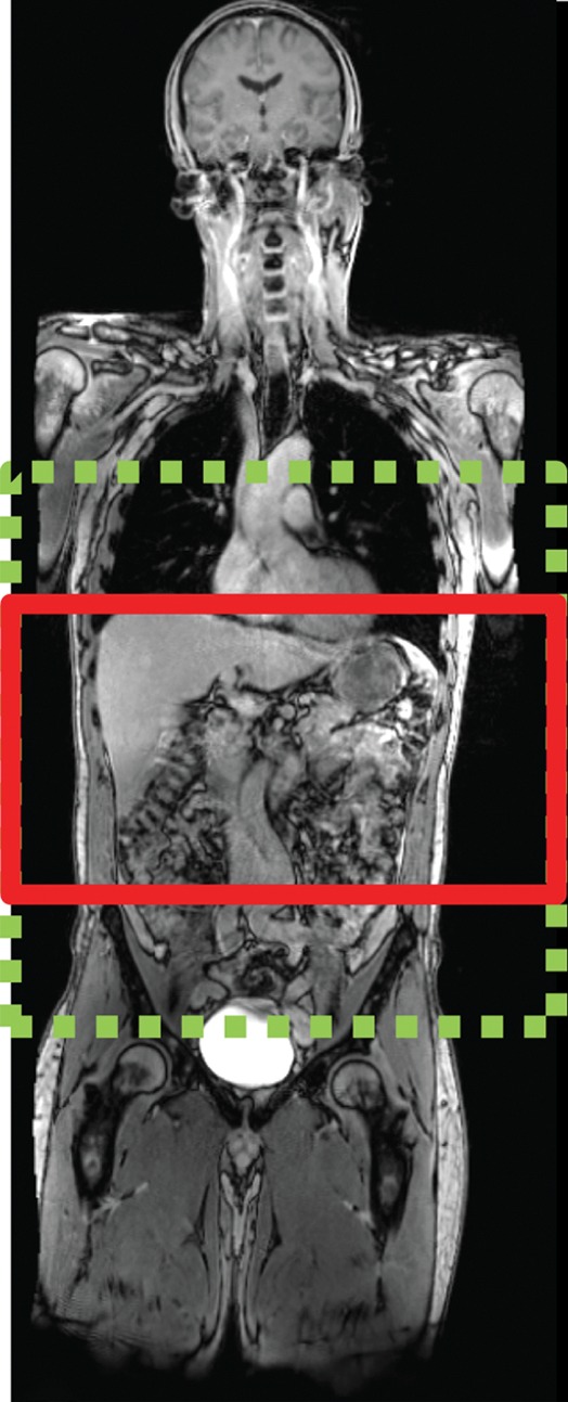
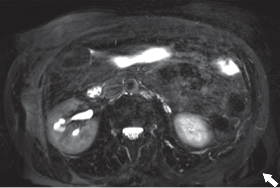
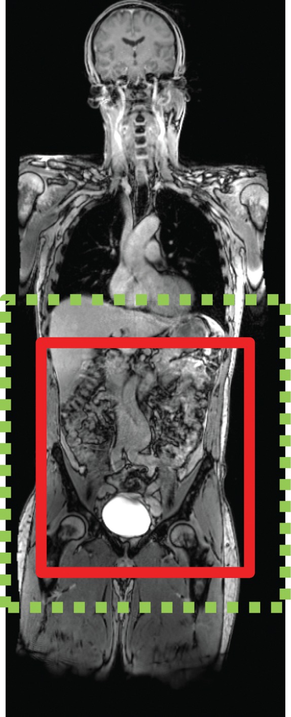
Echo-planar imaging artifacts at diffusion-weighted MR imaging. (a) Coronal whole-body contrast-enhanced MR image shows the B0 field (green dashed rectangle) and the excitation slab (red rectangle) for echo-planar diffusion-weighted imaging. (b) Axial diffusion-weighted MR image of the upper part of the abdomen shows the effect of B0 inhomogeneity over the lungs, which, in combination with poor fat suppression and eddy current effects, leads to noticeable phase-encoding artifact. (c) Axial diffusion-weighted MR image of the upper part of the abdomen obtained with improved shimming and with fat suppression shows decreased image distortion and better image quality.
Figure 6b.
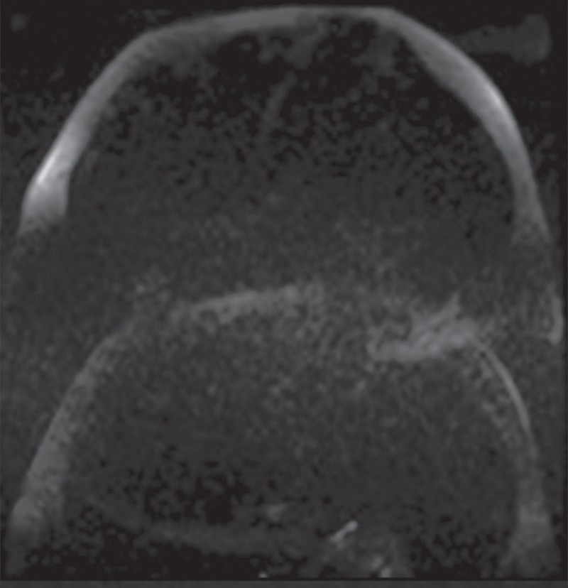
Echo-planar imaging artifacts at diffusion-weighted MR imaging. (a) Coronal whole-body contrast-enhanced MR image shows the B0 field (green dashed rectangle) and the excitation slab (red rectangle) for echo-planar diffusion-weighted imaging. (b) Axial diffusion-weighted MR image of the upper part of the abdomen shows the effect of B0 inhomogeneity over the lungs, which, in combination with poor fat suppression and eddy current effects, leads to noticeable phase-encoding artifact. (c) Axial diffusion-weighted MR image of the upper part of the abdomen obtained with improved shimming and with fat suppression shows decreased image distortion and better image quality.
Figure 6c.
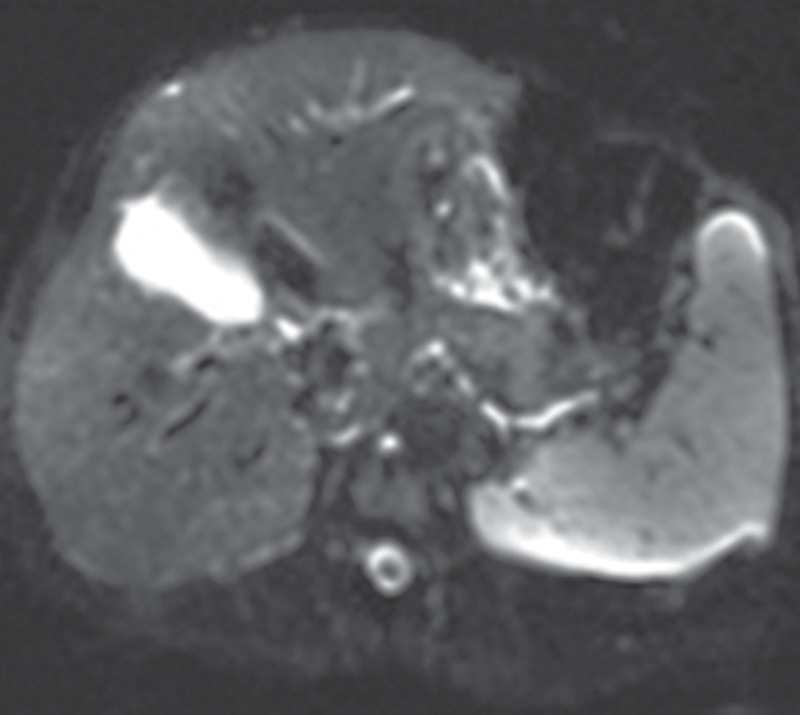
Echo-planar imaging artifacts at diffusion-weighted MR imaging. (a) Coronal whole-body contrast-enhanced MR image shows the B0 field (green dashed rectangle) and the excitation slab (red rectangle) for echo-planar diffusion-weighted imaging. (b) Axial diffusion-weighted MR image of the upper part of the abdomen shows the effect of B0 inhomogeneity over the lungs, which, in combination with poor fat suppression and eddy current effects, leads to noticeable phase-encoding artifact. (c) Axial diffusion-weighted MR image of the upper part of the abdomen obtained with improved shimming and with fat suppression shows decreased image distortion and better image quality.
Eddy Current Artifacts
Description.—Eddy currents are a major source of artifacts at diffusion-weighted imaging and echo-planar imaging because of the rapid switching of strong gradient pulses (14). Eddy currents are electrical currents created by the interaction of rapidly changing magnetic field gradients and other metallic or conducting surfaces in the MR imaging machine, such as specific cold shields in the magnet. The eddy currents induce additional magnetic field gradients in the surrounding cold shield or other conductive surfaces, which then are superimposed on the imaging gradients and cause errors in the local magnetic field for image formation. The resulting geometric distortions can take on several patterns, including contraction, dilatation, shifting, and shearing of the image, depending on the spatial formation of the eddy current fields and the gradient pulsing that induced them. Eddy current–related artifacts also scale with increasing gradient strength and duration and may be different for different magnet hardware configurations.
Solutions.—Actively shielded gradient coils are widely used for the minimization of eddy currents and have become a standard component of most MR imaging systems (15). These self-shielded gradient coils use additional wiring to decrease the effects of spurious magnetic field gradients outside the gradient coils. Proper calibration of the currents in the gradient hardware in a procedure known as preemphasis compensation can additionally minimize the effects of eddy currents (16). The combination of shielded gradient coils and eddy current preemphasis results in acceptable image quality with most diffusion-weighted imaging applications for body MR imaging.
RF Magnetic Field Inhomogeneity
Description.—Inhomogeneity in the applied RF magnetic field (B1) can result in image intensity variations that are based on transmission or reception. This effect can be particularly pronounced at body MR imaging because of the need to cover a large FOV. Transmission inhomogeneity may result from spatially varying pulse profiles generated by the body transmission coil. Because of the size (and therefore the low SNR) of the body coil, it is rarely used for signal reception. Instead, arrays of surface coils are typically used for signal reception. Inhomogeneous reception may result from the use of either surface coils or phased-array technology (17).
Dielectric Artifact (Standing Waves).—As field strength increases, the resonant frequency increases, as given by the Larmor relationship. Accounting for the dielectric properties of tissue, the wavelength of the RF transmission field is given by the relationship (17):
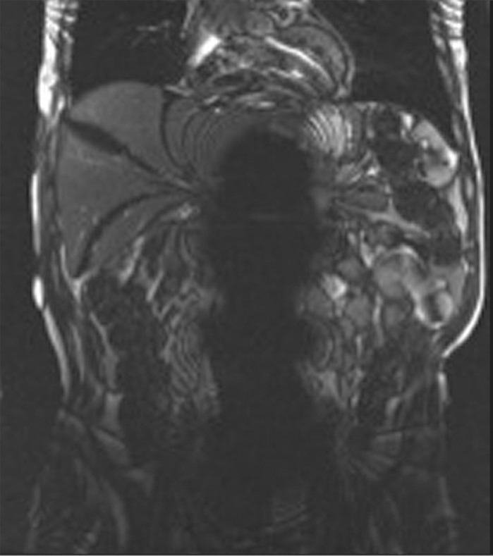
where λ is the wavelength, c is the speed of light (3 × 10⁸ m/sec), f0 is the resonant frequency, and ε is the dielectric constant of tissue. The wavelength is shortened by the high dielectric constant of tissue and also by the higher Larmor frequency at high field strengths. At 1.5 T, the wavelength is approximately 52 cm in soft tissue and larger than the size of the patient (axial dimension). At 3 T, the wavelength is approximately 26 cm in soft tissue, which approaches the size of many adults. The wavelength is two- to threefold higher in fat and bone and substantially shorter in fluid. When the RF wavelength is on the same order of magnitude as the dimension of the patient, noticeable variations in the B1 transmission field can occur to produce areas of increased or decreased signal intensity (Fig 7). These effects are especially pronounced at body imaging in which the imaged structures are large, for example, in the setting of pregnancy, obesity, or ascites.
Figure 7a.
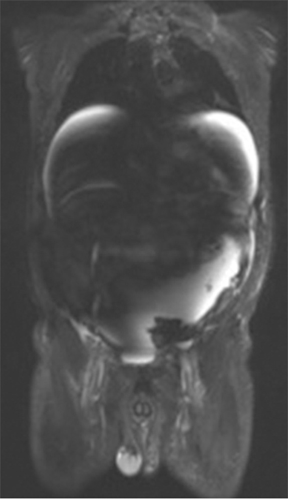
B1 inhomogeneity (standing waves) at 3-T MR imaging of a patient with cirrhosis and ascites. Coronal T2-weighted (a) and axial out-of-phase T1-weighted (b) MR images show a signal void in the center of the images because the wavelength of the RF transmission field is on the same order of magnitude as the dimension of the patient. The resulting variations in the RF transmission field produce focal areas of decreased signal intensity.
Figure 7b.
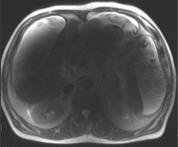
B1 inhomogeneity (standing waves) at 3-T MR imaging of a patient with cirrhosis and ascites. Coronal T2-weighted (a) and axial out-of-phase T1-weighted (b) MR images show a signal void in the center of the images because the wavelength of the RF transmission field is on the same order of magnitude as the dimension of the patient. The resulting variations in the RF transmission field produce focal areas of decreased signal intensity.
Solutions.—Several solutions can be used to alleviate artifacts caused by B1 inhomogeneity and standing wave artifacts: (a) dielectric pads, (b) lowering the field strength, (c) multichannel transmit arrays, and (d) RF shimming. A simple solution to mitigating variations in signal intensity that are due to wavelength effects at 3 T involves applying dielectric pads or cushions on the abdomen. These pads change the geometry of the subject and contain gel with a high dielectric constant, which decreases the wavelength of the RF field and reduces B1 inhomogeneity. Imaging the patient at 1.5 T instead of 3 T can often mitigate the shading artifacts that arise from standing waves at 3 T. More advanced approaches to improve B1 homogeneity include using multichannel transmit arrays to spatially tailor the RF waveforms and compensate for spatial variations in the B1 field (18,19). B1 shimming can also be used to improve the uniformity of the B1 field itself, analogous to shimming of the main B0 magnetic field. Nonuniformities in the receive field can be rectified in part through a process known as normalization, which uses a normalization filter to reduce signal inhomogeneity caused by RF attenuation that is due to variations in depth from the skin, analogous to the concept of time-gain compensation for ultrasonography.
Chemical Shift Artifacts
Description.—Fat and water protons precess at different frequencies because of differences in the chemical environment, which is known as chemical shift. Because spatial encoding at MR imaging relies on inferring the spatial position from the precession frequency, a water proton and a fat proton located at the same physical position will be slightly shifted within an image because of their different precession frequencies (Fig 8). This type of chemical shift artifact, also known as type I chemical shift artifact, occurs in the readout or frequency-encoding (kx) direction in non–echo-planar–based imaging. No chemical shift, however, will occur in the phase-encoding direction with conventional techniques. The spatial misregistration resulting from chemical shift is compounded at higher field strengths because the Larmor frequency is directly proportional to field strength (Fig 9). The difference in precession frequency between fat and water is approximately 3.5 ppm, which is about 220 Hz at 1.5 T and 440 Hz at 3 T. As an example, for a typical body width of 36 cm, typical matrix size of 180 in the frequency-encoding direction, and typical bandwidth of 500 Hz/pixel, the chemical shift of fat would lead to a shift relative to water of approximately 0.9 mm at 1.5 T and 1.8 mm at 3 T.
Figure 8.
Schematic diagram showing the origin of chemical shift artifacts. Fat and water protons resonate at different frequencies within the static magnetic field because of differences in the chemical environment. In the frequency-encoding direction (x-axis), the precession frequency difference between a fat proton (white square) and a water proton (black square) is translated directly into differences in physical position. No chemical shift artifact occurs in the phase-encoding direction (y-axis) for the fat and water protons (gray squares) with conventional pulse sequences. These differences are more pronounced at higher field strengths because the frequency difference is directly proportional to the field strength. MRI = MR imaging, NMR = nuclear magnetic resonance imaging.
Figure 9.
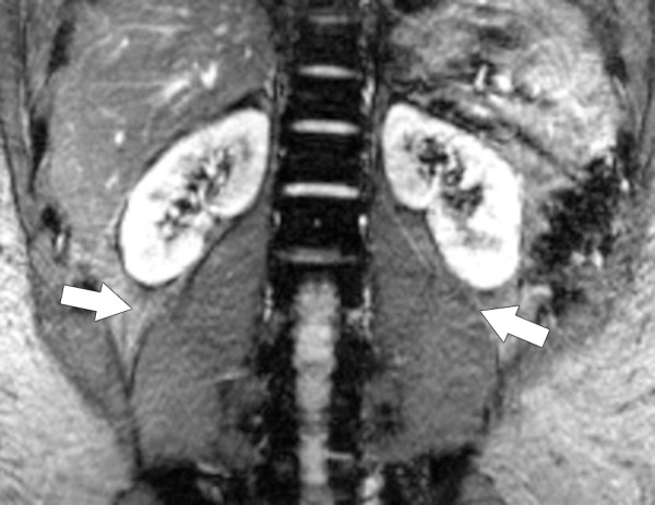
Type I chemical shift artifact. Coronal MR image of the retroperitoneum obtained at 3 T shows that spatial misregistration (arrows) caused by chemical shift differences between water and fat occurs along the frequency-encoding (readout) direction (craniocaudal direction) along the interface of the psoas muscle and the retroperitoneal fat.
In addition to spatial misregistration, gradient-echo sequences can show another type of chemical shift artifact, known as type II chemical shift artifact, black boundary artifact, or India ink artifact (Fig 10). This artifact arises when fat and water are present in the same voxel and manifests as a black border outlining the fat-water interfaces. Because of the differences in the precession frequency of protons in fat and water, the phases accumulated from chemical shift differences between fat and water may add or negate each other. Figure 10 shows examples of dual-echo gradient-echo images with echo times of 2.2 msec and 4.4 msec, corresponding to fat and water protons that are in phase and out of phase at 1.5 T, respectively. This artifact can be used to confirm the presence of fat within organs or lesions. Type II chemical shift artifact occurs only with gradient-echo sequences because the 180° pulse in spin-echo sequences refocuses the phase shift between fat and water protons.
Figure 10a.
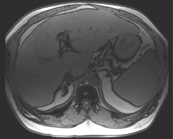
Type II chemical shift artifact. Axial dual-echo out-of-phase (echo time, 2.2 msec) (a) and in-phase (echo time, 4.4 msec) (b) gradient-echo MR images of the abdomen showing fat and water were obtained at 1.5 T. The out-of-phase image shows the characteristic black border outlining the fat-water interfaces that is due to the differences in chemical shift between fat and water in the same voxel.
Figure 10b.
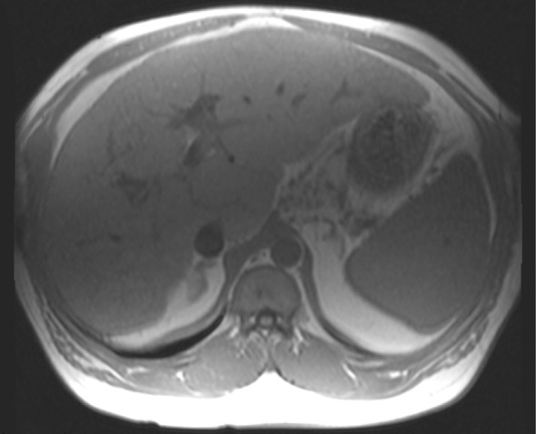
Type II chemical shift artifact. Axial dual-echo out-of-phase (echo time, 2.2 msec) (a) and in-phase (echo time, 4.4 msec) (b) gradient-echo MR images of the abdomen showing fat and water were obtained at 1.5 T. The out-of-phase image shows the characteristic black border outlining the fat-water interfaces that is due to the differences in chemical shift between fat and water in the same voxel.
Solutions.—Chemical shift artifact can be reduced through several simple adjustments to the imaging acquisition parameters: (a) swapping phase- and frequency-encoding directions, (b) increasing receiver bandwidth, and (c) applying fat suppression. Changing the phase- and frequency-encoding directions can rotate the signal superposition resulting from chemical shift differences in the tissues to a less compromising area of the image. Increasing the receiver bandwidth can also ameliorate chemical shift artifact by allowing each pixel to represent a greater frequency difference, thereby decreasing the pixel misregistration caused by chemical shift differences. Increasing the receiver bandwidth does come at the cost of decreasing the SNR; however, the decrease of the SNR can be compensated for by increasing the number of averages acquired or going to a higher magnetic field strength. For example, doubling the receiver bandwidth at 3 T will reduce the chemical shift artifact to the same level as at 1.5 T with a concomitant decrease in the SNR by √2 , or about 30%. Still, the SNR at 3 T is approximately 40% higher than at 1.5 T, which makes up for the decrease of the SNR caused by the increased bandwidth (5). If the chemical shift artifact continues to be problematic, fat suppression may be applied to remove the fat signal altogether, at the expense of a reduced SNR.
Fat Suppression
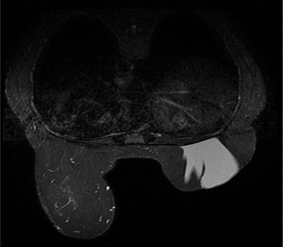
Description.—Fat suppression is used at body MR imaging to identify macroscopic fat within lesions, such as adrenal masses, to improve the conspicuity of lesions within or adjacent to fatty structures, and to improve the dynamic range for contrast-enhanced MR imaging with contrast agents that shorten the longitudinal relaxation time (T1) (eg, gadolinium-based contrast agents). Fat suppression can be achieved in a number of ways. Spectrally selective pulses applied at the resonance frequency of fat (ie, the lipid peak) are commonly used to achieve fat suppression. However, the efficacy of such chemical shift–sensitive saturation pulses can be compromised by inhomogeneity in the static B0 magnetic field or the RF B1 field. B0 inhomogeneity causes changes in Larmor frequency that are spatially dependent and shifts the fat resonance frequency away from the applied frequency of the spectrally selective pulse, rendering it ineffective (Fig 11). B1 nonuniformity may also lead to poor fat suppression through incorrect flip angles that lead to less-than-optimal suppression levels. In addition, the presence of breast implants (eg, saline or silicone) may cause failure of automatic identification of the lipid peak. However, because silicone has its own unique peak, it is possible to account for it when considering fat suppression.
Figure 11a.
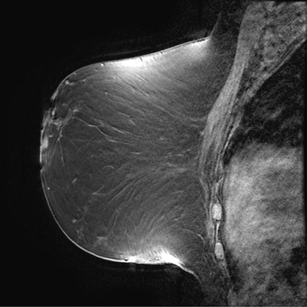
Poor fat suppression. (a, b) Sagittal (a) and axial (b) MR images show that B0 inhomogeneity leads to poor fat suppression in the breasts at the edges of the FOV. (c) Axial short inversion time inversion-recovery (STIR) MR image shows improved fat suppression with STIR.
Figure 11b.
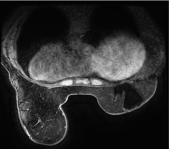
Poor fat suppression. (a, b) Sagittal (a) and axial (b) MR images show that B0 inhomogeneity leads to poor fat suppression in the breasts at the edges of the FOV. (c) Axial short inversion time inversion-recovery (STIR) MR image shows improved fat suppression with STIR.
Figure 11c.
Poor fat suppression. (a, b) Sagittal (a) and axial (b) MR images show that B0 inhomogeneity leads to poor fat suppression in the breasts at the edges of the FOV. (c) Axial short inversion time inversion-recovery (STIR) MR image shows improved fat suppression with STIR.
Solutions.—As with most artifacts arising from poor B0 homogeneity, improved shimming over the volume of interest should be one of the first steps taken to improve fat suppression. Other approaches to fat suppression that are less sensitive to B0 inhomogeneity can also be used, such as STIR sequences and spatial presaturation. STIR sequences rely on differences in T1 between fat and water to selectively null out the fat signal and are thus less sensitive to nonuniformities in the external magnetic field (Fig 11). However, STIR sequences are still sensitive to B1 inhomogeneity, which can be mitigated by using adiabatic inversion pulses that provide a more uniform RF excitation. Adiabatic pulses are created by modulating both the amplitude and phase of the RF pulse to rotate spins experiencing different B1 fields by the same flip angle (20). STIR sequences are particularly helpful for improving fat suppression in the vicinity of marked susceptibility variations and artifacts from metallic implants. It must be noted that STIR sequences necessitate longer acquisition times because of the long TR required for fully inverted magnetization, and SNR can suffer from partial reduction of the water signal in the process of nulling fat (21). In addition, substances with a short T1 similar to that of fat, such as methemoglobin, can also be partially suppressed by the STIR technique, making it difficult, for example, to distinguish fat in a teratoma from blood in an endometrioma. If fat suppression continues to be poor, spatial presaturation can be applied to reduce motion- and flow-related artifacts adjacent to or within an area intended for fat suppression.
Approaches to improving fat suppression caused by B1 inhomogeneity rely on tactics similar to those used for improving nonuniformities in the RF field in general. These solutions include shimming the B1 field (RF shimming) and using multichannel transmit arrays for tailored, uniform, and fast excitation.
RF Interference Artifacts
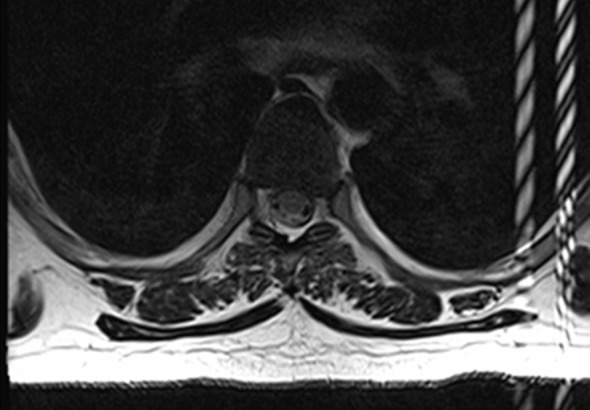
Description.—The MR receive coil acts as a sensitive antenna that is designed to detect RF signals arising from tissue. The MR imaging room is constructed as a Faraday cage, with copper shielding surrounding it to exclude spurious RF signals from outside the room. However, any stray RF signal can still be picked up, such as RF noise from electronic monitoring equipment brought into the MR imaging room. Typical noise sources may possess a distinct frequency bandwidth, leading to lines or bands along the frequency-encoding direction that have the appearance of a zipper (hence the alternative term zipper artifact) (Fig 12). Some sources may also have phase coherence, leading to more clearly defined patterns even along the phase-encoding direction. Extremely broadband noise may increase the background noise level, leading to a general reduction in the SNR and poor overall image quality.
Figure 12a.
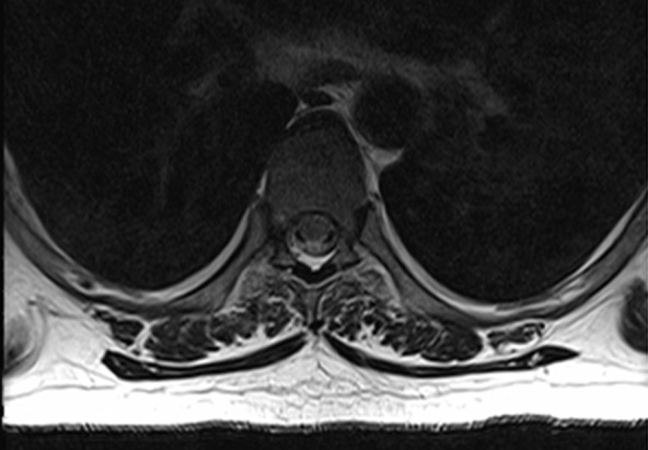
RF interference artifacts. Axial MR images show absence of RF interference artifacts (a) and presence of RF interference artifacts (b). RF noise arising from devices external to the patient or from improper shielding of the MR imaging room results in a characteristic line or band with the appearance of a zipper (hence the alternative term zipper artifact). Removing the source of RF interference will eliminate the artifacts.
Figure 12b.
RF interference artifacts. Axial MR images show absence of RF interference artifacts (a) and presence of RF interference artifacts (b). RF noise arising from devices external to the patient or from improper shielding of the MR imaging room results in a characteristic line or band with the appearance of a zipper (hence the alternative term zipper artifact). Removing the source of RF interference will eliminate the artifacts.
Solutions.—External RF noise can be avoided by making sure that the examination room door is closed during MR imaging and that peripheral devices in the room are designed for MR compatibility.
Motion Artifacts
Physiologic Motion–related Artifacts
Description.—Physiologic motion from respiration, cardiac activity, vascular pulsation, and bowel peristalsis is a major source of artifacts at body MR imaging. Cardiac motion is particularly problematic for thoracic and breast MR imaging. Motion artifacts manifest as image blurring, ghosting, signal intensity loss, and misregistration, usually in the phase-encoding direction. The signal is encoded to varied and incorrect locations because of signal phase shifts caused by the motion of the subject.
Motion—either voluntary or involuntary—causes magnitude and/or phase alterations in the optimal k-space encoding scheme. Magnitude errors occur during application of the RF pulse as the position of the magnetization excited within a voxel changes with time. Phase errors arise from phase shifts of the transverse magnetization as spins move along the direction of an applied gradient.
The direction and appearance of motion artifacts depend on when the motion occurred during k-space encoding (1). If the signal perturbation from motion occurs along the kx direction of k-space, ghosting will manifest in the frequency-encoding direction of the image. If motion occurs along the ky-axis of k-space, ghosting will appear in the phase-encoding direction of the image. Because the readout duration is short relative to phase encoding (which typically is the length of the entire imaging examination), most motion artifacts occur along the phase-encoding direction. If the motion is periodic (eg, respiratory or cardiac motion), the resultant ghosting artifact will also be periodic (Fig 13). If the motion is random and small in amplitude (eg, bowel peristalsis), the result will be a less-defined ghost or edge jitter. If the motion occurs during the encoding of the center of k-space, the image will be blurred or smeared.
Figure 13a.
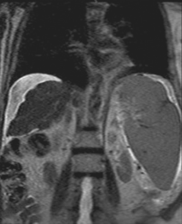
Motion artifact related to ascites in a 65-year-old man who was undergoing routine surveillance for hepatocellular carcinoma. Coronal (a) and axial (b) T2-weighted MR images show flow-related signal loss caused by motion within the ascites. Flow-related artifact within ascites can be confused with particulate material and peritonitis. The axial image also shows motion artifacts related to respiration, which manifest as periodic ghosts that are oriented parallel to the anterior abdominal wall.
Figure 13b.
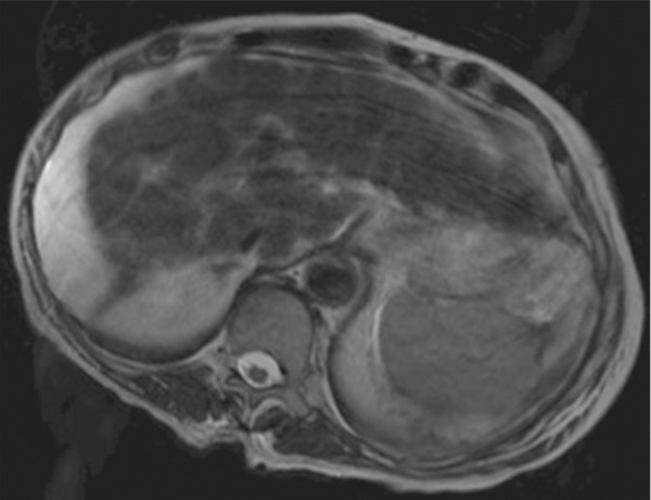
Motion artifact related to ascites in a 65-year-old man who was undergoing routine surveillance for hepatocellular carcinoma. Coronal (a) and axial (b) T2-weighted MR images show flow-related signal loss caused by motion within the ascites. Flow-related artifact within ascites can be confused with particulate material and peritonitis. The axial image also shows motion artifacts related to respiration, which manifest as periodic ghosts that are oriented parallel to the anterior abdominal wall.
Solutions.—Motion artifacts tend to be most pronounced in uncooperative patients and sequences with long acquisition times, including long TR and three-dimensional imaging sequences. A wide variety of approaches have been developed to deal with motion artifacts at body MR imaging (22). These approaches include synchronization of image acquisition to respiratory motion, changes in the acquisition parameters to minimize the effect of motion on image quality, and accelerated image acquisition (Table).
Solutions for Motion Artifacts
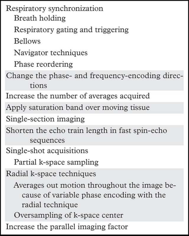
Common approaches to compensate for re+spiratory motion include (a) breath holding, (b) respiratory gating and triggering, (c) bellows, (d) navigator techniques, and (e) k-space view or phase reordering. Breath holding requires patient cooperation and may be more difficult for young children and patients with respiratory or neurologic conditions. Alternatively, respiration may be monitored with a pneumatic bellows, which is secured around the patient’s abdomen by a belt and detects changes in pressure related to lung expansion and contraction. Image acquisition is then timed to the end of expiration, when respiratory motion is minimal. Potential disadvantages of respiratory bellows include the added time for setup of the apparatus and the increased image acquisition times. Navigator techniques monitor respiratory motion without added equipment by applying an additional pulse to selectively excite magnetization over the diaphragm and produce a one-dimensional real-time tracing of diaphragmatic excursion (Fig 14). The resulting echo signals can then be used to limit image acquisition prospectively to the end of expiration or to retrospectively select out imaging data that were acquired at end expiration (eg, at the maximum height of the diaphragm) and obtain an image with reduced motion artifacts.
Figure 14a.
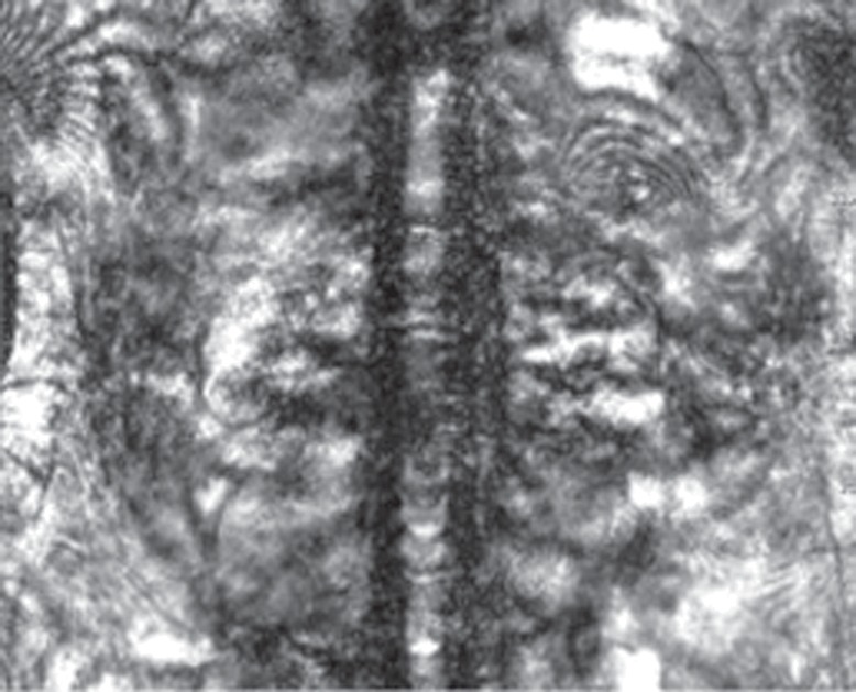
Respiratory motion compensation with a navigator sequence. (a, b) Coronal gradient-echo MR images obtained without (a) and with (b) respiratory synchronization by using a navigator sequence. (c) Coronal MR image shows the result of using the navigator sequence; the green rectangle demonstrates placement of an additional pulse to excite magnetization over the diaphragm, which allows a one-dimensional real-time tracing of diaphragmatic excursion. From this information, imaging can be timed prospectively or reconstructed retrospectively to minimize motion related to respiration.
Figure 14b.
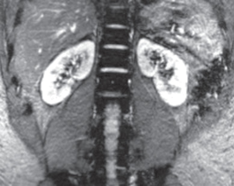
Respiratory motion compensation with a navigator sequence. (a, b) Coronal gradient-echo MR images obtained without (a) and with (b) respiratory synchronization by using a navigator sequence. (c) Coronal MR image shows the result of using the navigator sequence; the green rectangle demonstrates placement of an additional pulse to excite magnetization over the diaphragm, which allows a one-dimensional real-time tracing of diaphragmatic excursion. From this information, imaging can be timed prospectively or reconstructed retrospectively to minimize motion related to respiration.
Figure 14c.
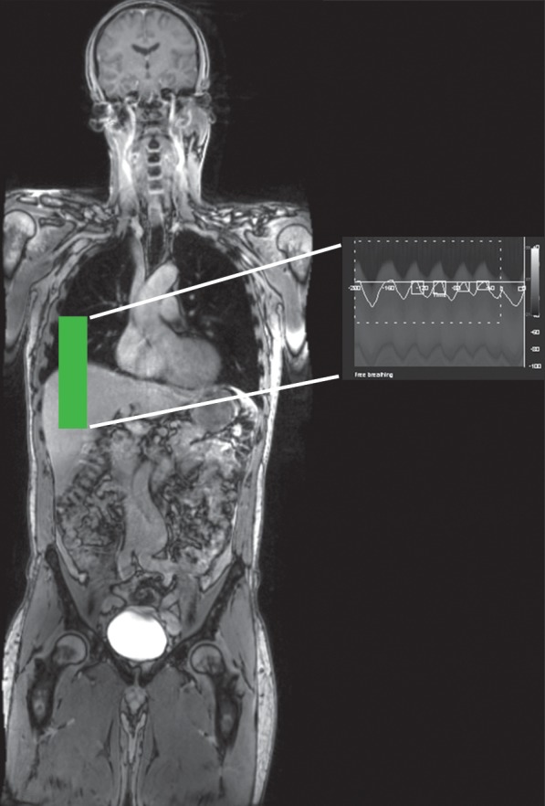
Respiratory motion compensation with a navigator sequence. (a, b) Coronal gradient-echo MR images obtained without (a) and with (b) respiratory synchronization by using a navigator sequence. (c) Coronal MR image shows the result of using the navigator sequence; the green rectangle demonstrates placement of an additional pulse to excite magnetization over the diaphragm, which allows a one-dimensional real-time tracing of diaphragmatic excursion. From this information, imaging can be timed prospectively or reconstructed retrospectively to minimize motion related to respiration.
Phase reordering involves rearranging the acquisition of data in k-space to minimize the effect of motion on the resulting image. In respiratory-ordered phase encoding (23), the most negative k-space views are acquired when respiratory motion is minimal (ie, end expiration), and the most positive k-space views are obtained when respiratory motion is greatest (ie, end inspiration). Another scheme known as centric-ordered phase encoding (24) involves (a) acquiring the edges of k-space (ie, points with the highest spatial resolution) at end expiration because they are the most prone to motion degradation and (b) acquiring the center points of k-space (ie, points with the most tissue contrast) at end inspiration because they are relatively robust with regard to motion.
Changing the phase- and frequency-encoding directions is a simple modification to the imaging acquisition parameters that can rotate motion artifacts to areas of the image that will not compromise image interpretation. Another straightforward approach to ameliorating motion artifacts is to acquire signals across multiple respiratory cycles, which can decrease the relative contribution of motion-degraded signal to the overall image. This approach improves the SNR by the square root of the resulting increase in imaging time. Another simple solution is to apply a saturation band over the moving tissue to eliminate its signal and potential ghosting from the image. This approach works particularly well for superficial portions of the body, such as the anterior abdominal wall fat. Instead of acquiring multiple interleaved sections within a given TR, which is a commonly used approach to decrease acquisition time, limiting the imaged area to a single section may be effective in particularly motion-prone areas of the body.
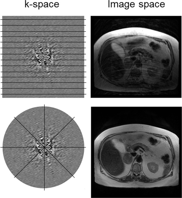
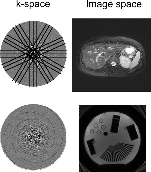
Accelerating image acquisition in motion-prone areas can help to mitigate motion artifacts. This acceleration can be achieved by varying the k-space sampling approach. With fast spin-echo sequences, reducing the echo train length can decrease image blurring caused by motion during the echo train acquisition at the expense of longer imaging times. Single-shot imaging techniques such as the rapid acquisition with relaxation enhancement (RARE) sequence or the half-Fourier RARE sequence can also allow more rapid acquisition by sampling only half of k-space and can typically be done in a single breath hold. Alternative k-space sampling methods include radial acquisition, in which k-space is sampled in radial segments that are rotated around the center of k-space (Fig 15). By changing the phase-encoding direction for each repetition, radial k-space sampling tends to be more robust to motion compared with conventional rectilinear k-space sampling, in which the phase-encoding direction is fixed in a particular direction (Fig 15). Radial k-space sampling has inherently lower spatial resolution than conventional rectilinear approaches because of the oversampling of the center of k-space and the undersampling of the periphery of k-space, which contains high-spatial-frequency information required to resolve detailed structures. A related but separate technique known as periodically rotated overlapping parallel lines with enhanced reconstruction (PROPELLER, GE Healthcare; or BLADE, Siemens Healthcare) samples k-space by using a combination of rectilinear and radial trajectories. Each “blade” is a Cartesian segment of k-space that is rotated radially to fill k-space (Fig 16). The oversampled central k-space data are then used to correct for rotational and translational motions that occurred during image acquisition. The effect of the PROPELLER or BLADE technique on the image is similar to that of radial sampling but results in faster and more uniform sampling than with radial techniques. Spiral k-space acquisition can also help ameliorate motion artifact by acquiring k-space data with higher temporal resolution than with rectilinear sampling (Fig 16).
Figure 15.
Radial k-space acquisition to minimize motion artifact. Top row: With conventional rectilinear sampling, signal perturbations caused by bulk motion produce ghosts in the phase-encoding direction on the axial MR image (top right). Bottom row: When radial sampling is used, ghosting no longer is generated in a particular direction on the axial MR image (bottom right).
Figure 16.
Periodically rotated overlapping parallel lines with enhanced reconstruction and spiral k-space acquisition for mitigating motion artifact. Top row: The periodically rotated overlapping parallel lines with enhanced reconstruction techniques (PROPELLER or BLADE) use a combination of rectilinear and radial trajectories in each blade to correct for motion artifacts on the axial MR image (top right). Bottom row: Spiral k-space trajectories are also robust to motion because of their faster acquisition compared with conventional rectilinear sampling strategies.
Parallel imaging takes advantage of multichannel multicoil receiver arrays to decrease the number of phase-encoding steps and accelerate image acquisition. Despite the potential decrease in imaging time, typically on the order of two to three times, parallel imaging can decrease the SNR, incur signal loss in areas covered by nonfunctioning coil elements, and produce artifacts of its own (see “Parallel Imaging”).
Flow-related Artifacts
Description.—The motion of blood flowing through vessels generates flow-related artifacts that may be considered a boon (eg, time-of-flight MR angiography) or a detriment to imaging, depending on the application. On body MR images, flow-related artifacts manifest as signal loss (Fig 13) and ghosting caused by the shifts in phase of the transverse magnetization as blood flows through the imaging plane. In the absence of flow, stationary spins will be entirely refocused by dephasing and rephasing gradients of equal magnitude and opposite direction. In the presence of flow, moving spins accrue additional increments in phase that are not refocused by matched dephasing and rephasing gradients. Flow-related artifacts tend to become more pronounced with increasing echo time because of the larger phase errors accumulated during the longer echo time.
Solutions.—The standard approach to flow compensation involves modifying the gradient waveform to eliminate the effects of flow through a process known as gradient moment nulling. Gradient moment nulling is achieved by applying additional gradient lobes to remove the phase errors accrued by moving spins while still refocusing the signal from stationary spins (25). First-order gradient moment nulling compensates for constant-velocity flow and is usually sufficient for most body MR imaging applications. The additional gradient lobes are typically applied in the frequency- or section-selective encoding directions because the phase-encoding gradients are usually too weak to contribute appreciably to flow-related artifacts (1).
An alternative to gradient moment nulling involves applying saturation pulses above or below the imaging plane to decrease the signal from the inflow of blood. With saturation pulses, the number of sections that can be covered within a given TR may be limited because of the recovery of the saturated magnetization by T1 relaxation. Furthermore, as with all applications dealing with saturation pulses, limitations in the specific absorption rate may determine whether such pulses can be incorporated into the pulse sequence.
Artifacts Related to Image Digitization and Postprocessing
This section addresses artifacts that arise from the data collection methods used to sample the MR signal. The MR signal is a continuous signal that is detected, sampled, and stored as finite digitized data. Conversion of the MR imaging signal from the analog domain to digitized data necessarily involves truncations and discrete sampling of k-space.
Parallel Imaging
Description.—Parallel imaging has been discussed in brief in previous sections. Parallel imaging involves placing an array of surface receive coils that are electronically linked in position over the body part to be imaged and using their spatially localized sensitivity to subsample k-space and thereby decrease the overall number of phase-encoding steps (26). Parallel imaging improves temporal resolution by allowing spatial encoding to be performed across the coil elements simultaneously and undersampling k-space. The improvement in temporal resolution, however, has a deleterious effect on the SNR and is inversely related to the desired SNR by the following relationship:
where g, the geometry factor, is a factor inversely related to the degree of coil element independence; and X is the parallel imaging factor (1). Therefore, the trade-off for faster imaging with parallel imaging is a lower SNR.
By undersampling k-space, the increment between phase-encoding steps is increased, and the FOV for each coil is decreased, thereby resulting in aliasing (see “Aliasing”). The coil sensitivity factors, which are known for each coil, are used to unwrap the images. The two main approaches to parallel imaging deal either with k-space data, as in GRAPPA (11), or with image data after reconstruction, as in SENSE (10).
Parallel imaging artifacts are caused by a number of factors related to image acquisition and reconstruction. When areas of aliased signal are not well separated because of similarities in the signal intensity profile, this type of artifact can manifest as areas of low SNR caused by inadequate coil localization, usually occurring in the center of the patient, where there is the greatest overlap in signal (Fig 17). These effects are exacerbated with poor coil geometry factors and high acceleration. Malfunctioning of coil elements leads to signal loss in the area covered by the defective coil (Fig 18). Inaccuracies in the coil sensitivity maps can also lead to artifacts in parallel imaging. The sensitivity maps are typically acquired during calibration acquisition, which occurs before image acquisition. If the patient or coils move relative to each other after the calibration acquisition, this movement can lead to inaccurate coil sensitivity maps and incomplete unwrapping of the image data, which can appear as ghosting or signal loss across the center of the image (26).
Figure 17.
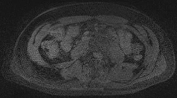
Parallel imaging artifact. Axial MR image shows that the central band of noise artifact is exacerbated by poor coil geometry factors and high acceleration.
Figure 18a.
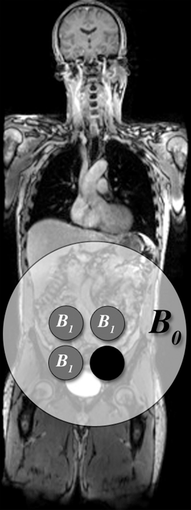
Parallel imaging artifact caused by a missing multichannel receive coil in a 47-year-old woman undergoing evaluation for uterine fibroids. (a) Coronal T2-weighted MR image shows placement of the parallel imaging receive coil array over the patient. The large light-gray circle represents B0, and multichannel receive coils (small dark-gray circles) overlie the pelvis. One of the lower coil elements is out (black circle). (b) Axial T2-weighted MR image shows marked signal loss (arrow) in the left anterior portion of the pelvis.
Figure 18b.
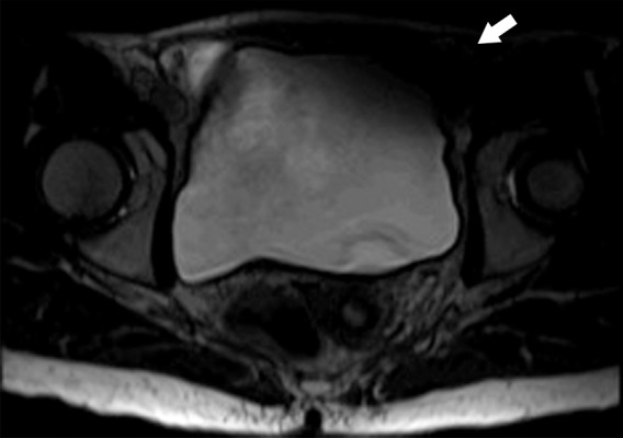
Parallel imaging artifact caused by a missing multichannel receive coil in a 47-year-old woman undergoing evaluation for uterine fibroids. (a) Coronal T2-weighted MR image shows placement of the parallel imaging receive coil array over the patient. The large light-gray circle represents B0, and multichannel receive coils (small dark-gray circles) overlie the pelvis. One of the lower coil elements is out (black circle). (b) Axial T2-weighted MR image shows marked signal loss (arrow) in the left anterior portion of the pelvis.
Solutions.—Signal loss caused by malfunctioning coil elements requires repair of the defective receive coil. Artifacts that are due to suboptimal calibration can be corrected by repeating the calibration acquisition. If the FOV of the calibration imaging is too small, aliasing within the calibration acquisition may result, which will translate into artifacts in the reconstructed images. Use of a large FOV that is centered within the desired imaging area for the calibration acquisition will help eliminate this artifact.
Aliasing
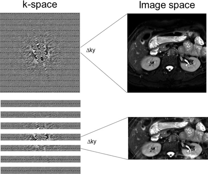
Description.—The inherent low sensitivity of MR imaging imposes trade-offs between the SNR and spatial and temporal resolution with all sequences. A smaller FOV allows for higher spatial resolution at the cost of a lower SNR. Aliasing, or the wraparound artifact, occurs when the FOV of encoding is smaller than the imaged anatomic structures. Because aliasing relates to k-space sampling, if the signal is insufficiently sampled or undersampled, the Fourier transform does not have the ability to uniquely map the signal in image space. Mathematically, there is an inverse relationship between k-space sampling and image space encoding. The finer the sampling in k-space (smaller Δky, for example), the larger the FOV dimension of the image. So, if k-space is sampled only every other line, the Δky is doubled and the FOV is halved, leading to aliasing because of the undersampling (Fig 19). Parallel acquisition techniques such as GRAPPA or SENSE are used to synthesize the missing lines from undersampling in k-space and therefore remove the aliasing (Fig 19). Radial acquisition is also less prone to aliasing artifacts. When the sampling rate in k-space is insufficient to capture the spatial extent of an imaged object, wraparound artifact occurs (Figs 20, 21).
Figure 19.
Aliasing and undersampling of k-space. Top row: Aliasing, or wraparound artifact, occurs when the FOV of encoding is smaller than the imaged anatomic structures. The finer the sampling in k-space (eg, smaller Δky), the larger the FOV dimension of the image. Bottom row: When k-space is sampled only with every other line, the Δky is doubled and the FOV is halved, leading to aliasing caused by the undersampling. Parallel acquisition techniques such as GRAPPA or SENSE are used to synthesize the missing lines from the undersampling in k-space and therefore remove the aliasing.
Figure 20a.
Aliasing artifact. (a) Axial T2-weighted MR image of the abdomen shows an aliasing artifact, or wraparound artifact, of the arms in the expected location of the flanks (arrow). (b) Coronal T1-weighted MR image shows the imaged FOV (red rectangle). The aliasing artifact could be mitigated with oversampling in the phase-encoding direction (green dashed rectangle).
Figure 21a.
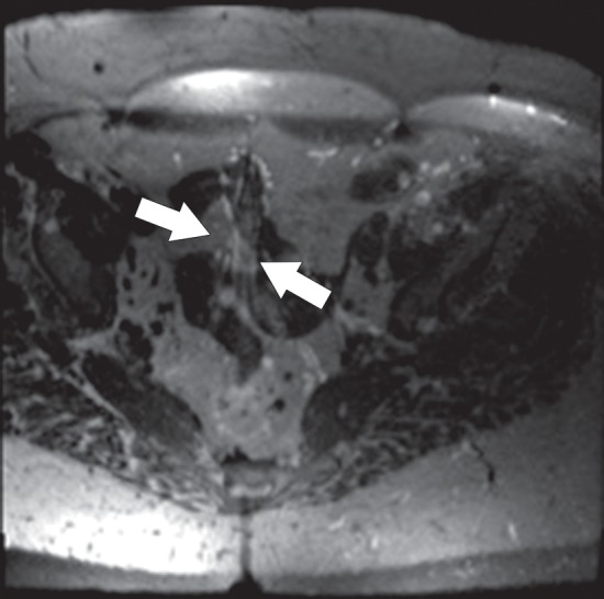
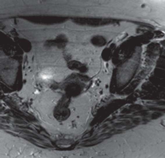
Aliasing artifact along the section direction in a three-dimensional acquisition. (a) Axial T2-weighted MR image acquired with a three-dimensional fast spin-echo sequence (SPACE [Sampling Perfection with Application optimized Contrasts using different flip angle Evolutions]; Siemens Healthcare) shows an artifact from the perineum (arrows) overlying the upper portion of the pelvis. (b) Repeat axial T2-weighted fast spin-echo (SPACE) MR image with oversampling in the section direction shows amelioration of the artifact at the cost of increased imaging time. (c) Coronal T2-weighted MR image shows the imaged FOV (red rectangle) and the oversampled volume (green dashed rectangle).
Figure 20b.

Aliasing artifact. (a) Axial T2-weighted MR image of the abdomen shows an aliasing artifact, or wraparound artifact, of the arms in the expected location of the flanks (arrow). (b) Coronal T1-weighted MR image shows the imaged FOV (red rectangle). The aliasing artifact could be mitigated with oversampling in the phase-encoding direction (green dashed rectangle).
Figure 21b.
Aliasing artifact along the section direction in a three-dimensional acquisition. (a) Axial T2-weighted MR image acquired with a three-dimensional fast spin-echo sequence (SPACE [Sampling Perfection with Application optimized Contrasts using different flip angle Evolutions]; Siemens Healthcare) shows an artifact from the perineum (arrows) overlying the upper portion of the pelvis. (b) Repeat axial T2-weighted fast spin-echo (SPACE) MR image with oversampling in the section direction shows amelioration of the artifact at the cost of increased imaging time. (c) Coronal T2-weighted MR image shows the imaged FOV (red rectangle) and the oversampled volume (green dashed rectangle).
Figure 21c.
Aliasing artifact along the section direction in a three-dimensional acquisition. (a) Axial T2-weighted MR image acquired with a three-dimensional fast spin-echo sequence (SPACE [Sampling Perfection with Application optimized Contrasts using different flip angle Evolutions]; Siemens Healthcare) shows an artifact from the perineum (arrows) overlying the upper portion of the pelvis. (b) Repeat axial T2-weighted fast spin-echo (SPACE) MR image with oversampling in the section direction shows amelioration of the artifact at the cost of increased imaging time. (c) Coronal T2-weighted MR image shows the imaged FOV (red rectangle) and the oversampled volume (green dashed rectangle).
Solutions.—Aliasing can be compensated for by increasing the FOV, placing saturation bands on areas outside the desired FOV to prevent unwanted signal from folding back into the image, changing the phase- and frequency-encoding directions, and oversampling in the phase- or frequency-encoding direction. Oversampling in the frequency-encoding direction can be achieved without appreciably changing the acquisition time simply by increasing the sampling rate during the signal sampling and readout interval. On the other hand, oversampling in the phase- or section-encoding directions of a three-dimensional imaging examination (Fig 21) will increase the imaging time proportionally because of the extra phase- and section-encoding steps needed to increase the sampling in ky and kz.
Truncation Artifacts
Description.—Although low sampling rates can lead to aliasing artifacts, an insufficient extent of sampling from truncation can create other artifacts in the spatial domain. Truncation artifact, or Gibbs ringing, is caused by the fact that the MR signal is truncated in k-space because it has to be finitely sampled. As a consequence, high-spatial-frequency information is lost, and the approximation errors associated with the Fourier transform lead to a ringing effect at boundaries in the image. From an imaging perspective, truncation artifact increases as the spatial resolution of encoding is decreased (Fig 22). Incomplete sampling of high-frequency information leads to image oscillations or ripples in areas of sharp transitions in signal intensity. Truncation artifact is typically more severe in the phase-encoding direction because Gibbs ringing is more prominent at the lower spatial resolutions used in this direction to reduce imaging time.
Figure 22.
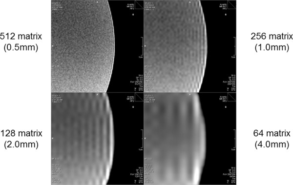
Truncation (Gibbs ringing) artifact. Truncation artifact, or Gibbs ringing, is caused by truncation of the signal in k-space that is due to the fact that the MR signal is finitely sampled. As a consequence, high-spatial-frequency information is lost, and the approximation errors associated with the Fourier transform lead to a ringing effect at boundaries in the image. From an imaging perspective, truncation artifact increases as the spatial resolution of encoding is decreased.
Solutions.—To decrease the amount of Gibbs ringing or truncation artifact, a common approach is to apply a smoothing filter in the k-space data before image reconstruction. The trade-off is blurring that is proportionate to the amount of smoothing applied. Alternatively, truncation artifact can be reduced by acquiring higher-spatial-resolution data, but this alternative requires more phase-encoding steps at the cost of prolonging image acquisition and decreasing the SNR.
Conclusion
Body MR imaging is a field that continues to evolve with improving coil technology and higher-field-strength imaging. Body MR imaging is challenged by involuntary patient motion, respiratory motion, bowel peristalsis, and bowel gas. The combination of these factors has made body MR imaging ripe for artifacts and has increased the challenges of consistent image quality. Practitioners of body MR imaging need to understand enough MR physics to recognize artifacts as they occur and to appreciate the trade-offs necessary in attempts to mitigate them. Protocol design requires that artifacts be anticipated, to avoid poor patient compliance and nondiagnostic results.
Recipient of a Certificate of Merit award for an education exhibit at the 2013 RSNA Annual Meeting.
For this journal-based SA-CME activity, the authors R.T.S., J.E.K., and A.R.G. have provided disclosures (see “Disclosures of Conflicts of Interest”); all other authors, the editor, and the reviewers have disclosed no relevant relationships.
Funding: The work was supported by the National Institutes of Health [grant number K08EB012859].
Disclosures of Conflicts of Interest.—: A.R.G. Activities related to the present article: disclosed no relevant relationships. Activities not related to the present article: speaker for Siemens Medical Solutions; expert witness for Rice, Dolan & Kershaw. Other activities: disclosed no relevant relationships. J.E.K. Activities related to the present article: employee of Siemens Healthcare. Activities not related to the present article: disclosed no relevant relationships. Other activities: disclosed no relevant relationships. R.T.S. Activities related to the present article: employee of Siemens Healthcare. Activities not related to the present article: disclosed no relevant relationships. Other activities: disclosed no relevant relationships.
Abbreviations:
- B0
- static magnetic field
- B1
- applied radiofrequency field
- FOV
- field of view
- RARE
- rapid acquisition with relaxation enhancement
- RF
- radiofrequency
- SNR
- signal-to-noise ratio
- SSFP
- steady-state free precession
- STIR
- short inversion time inversion-recovery
- TR
- repetition time
References
- 1.Morelli JN, Runge VM, Ai F, et al. An image-based approach to understanding the physics of MR artifacts. RadioGraphics 2011;31(3):849–866. [DOI] [PubMed] [Google Scholar]
- 2.Chavhan GB, Babyn PS, Thomas B, Shroff MM, Haacke EM. Principles, techniques, and applications of T2*-based MR imaging and its special applications. RadioGraphics 2009;29(5):1433–1449. [DOI] [PMC free article] [PubMed] [Google Scholar]
- 3.Bernstein MA, Huston J, 3rd, Ward HA. Imaging artifacts at 3.0T. J Magn Reson Imaging 2006;24(4):735–746. [DOI] [PubMed] [Google Scholar]
- 4.Merkle EM, Dale BM. Abdominal MRI at 3.0 T: the basics revisited. AJR Am J Roentgenol 2006;186(6):1524–1532. [DOI] [PubMed] [Google Scholar]
- 5.Dietrich O, Reiser MF, Schoenberg SO. Artifacts in 3-T MRI: physical background and reduction strategies. Eur J Radiol 2008;65(1):29–35. [DOI] [PubMed] [Google Scholar]
- 6.Lu W, Pauly KB, Gold GE, Pauly JM, Hargreaves BA. SEMAC: slice encoding for metal artifact correction in MRI. Magn Reson Med 2009;62(1):66–76. [DOI] [PMC free article] [PubMed] [Google Scholar]
- 7.Koch KM, Lorbiecki JE, Hinks RS, King KF. A multispectral three-dimensional acquisition technique for imaging near metal implants. Magn Reson Med 2009;61(2):381–390. [DOI] [PubMed] [Google Scholar]
- 8.Scheffler K, Lehnhardt S. Principles and applications of balanced SSFP techniques. Eur Radiol 2003;13(11): 2409–2418. [DOI] [PubMed] [Google Scholar]
- 9.Mansfield P. Multi-planar image formation using NMR spin echoes. J Phys C Solid State Phys 1977;10(3):L55–L58. [Google Scholar]
- 10.Pruessmann KP, Weiger M, Scheidegger MB, Boesiger P. SENSE: sensitivity encoding for fast MRI. Magn Reson Med 1999;42(5):952–962. [PubMed] [Google Scholar]
- 11.Griswold MA, Jakob PM, Heidemann RM, et al. Generalized autocalibrating partially parallel acquisitions (GRAPPA). Magn Reson Med 2002;47(6):1202–1210. [DOI] [PubMed] [Google Scholar]
- 12.Dietrich O, Biffar A, Baur-Melnyk A, Reiser MF. Technical aspects of MR diffusion imaging of the body. Eur J Radiol 2010;76(3):314–322. [DOI] [PubMed] [Google Scholar]
- 13.Porter DA, Heidemann RM. High resolution diffusion-weighted imaging using readout-segmented echo-planar imaging, parallel imaging and a two-dimensional navigator-based reacquisition. Magn Reson Med 2009;62(2): 468–475. [DOI] [PubMed] [Google Scholar]
- 14.Reese TG, Heid O, Weisskoff RM, Wedeen VJ. Reduction of eddy-current-induced distortion in diffusion MRI using a twice-refocused spin echo. Magn Reson Med 2003;49(1):177–182. [DOI] [PubMed] [Google Scholar]
- 15.Mansfield P, Chapman B. Active magnetic screening of gradient coils in NMR imaging. J Magn Reson 1986;66(3): 573–576. [Google Scholar]
- 16.Papadakis NG, Martin KM, Pickard JD, Hall LD, Carpenter TA, Huang CL. Gradient preemphasis calibration in diffusion-weighted echo-planar imaging. Magn Reson Med 2000;44(4):616–624. [DOI] [PubMed] [Google Scholar]
- 17.Graves MJ, Mitchell DG. Body MRI artifacts in clinical practice: a physicist’s and radiologist’s perspective. J Magn Reson Imaging 2013;38(2):269–287. [DOI] [PubMed] [Google Scholar]
- 18.Katscher U, Börnert P, Leussler C, van den Brink JS. Transmit SENSE. Magn Reson Med 2003;49(1):144–150. [DOI] [PubMed] [Google Scholar]
- 19.Zhu Y. Parallel excitation with an array of transmit coils. Magn Reson Med 2004;51(4):775–784. [DOI] [PubMed] [Google Scholar]
- 20.Tannús A, Garwood M. Adiabatic pulses. NMR Biomed 1997;10(8):423–434. [DOI] [PubMed] [Google Scholar]
- 21.Bley TA, Wieben O, François CJ, Brittain JH, Reeder SB. Fat and water magnetic resonance imaging. J Magn Reson Imaging 2010;31(1):4–18. [DOI] [PubMed] [Google Scholar]
- 22.Yang RK, Roth CG, Ward RJ, deJesus JO, Mitchell DG. Optimizing abdominal MR imaging: approaches to common problems. RadioGraphics 2010;30(1):185–199. [DOI] [PubMed] [Google Scholar]
- 23.Bailes DR, Gilderdale DJ, Bydder GM, Collins AG, Firmin DN. Respiratory ordered phase encoding (ROPE): a method for reducing respiratory motion artefacts in MR imaging. J Comput Assist Tomogr 1985;9(4):835–838. [PubMed] [Google Scholar]
- 24.Haacke EM, Patrick JL. Reducing motion artifacts in two-dimensional Fourier transform imaging. Magn Reson Imaging 1986;4(4):359–376. [DOI] [PubMed] [Google Scholar]
- 25.Hinks RS, Constable RT. Gradient moment nulling in fast spin echo. Magn Reson Med 1994;32(6):698–706. [DOI] [PubMed] [Google Scholar]
- 26.Glockner JF, Hu HH, Stanley DW, Angelos L, King K. Parallel MR imaging: a user’s guide. RadioGraphics 2005;25(5):1279–1297. [DOI] [PubMed] [Google Scholar]


